R33C4LGWMWIFI MODULE
Snap One, LLC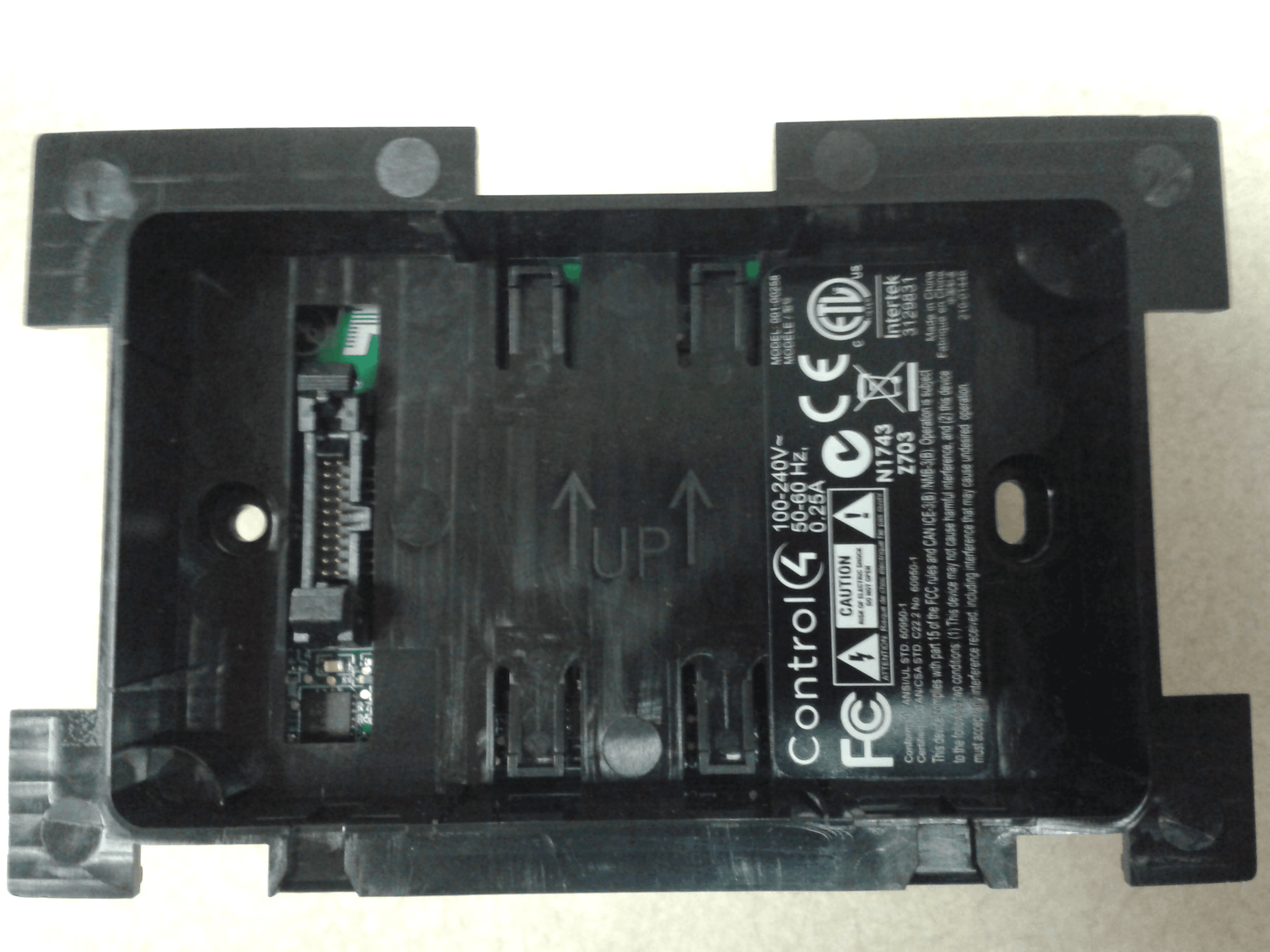
Click to zoom
Application Details
- Equipment Class
- DTS - Digital Transmission System
- Date of Grant
- Mar 24, 2015
- Application Purpose
- Original Equipment
- Date of Application
- Mar 24, 2015
- Equipment Note
- WIFI MODULE
- Frequency Range
- 2412.00000000 - 2462.00000000
- Company
- Snap One, LLC
- Country
- United States
Documents & Files
Document Text
Text extracted from the exhibit documents filed with the FCC. Open a document above to read the original.
Users Manual
11 Supported models • C4-WALL7-BL 7" T3-7 In-Wall Touch Screen, Black • C4-WALL7-WH 7" T3-7 In-Wall Touch Screen, White • C4-WALL10-BL 10" T3-10 In-Wall Touch Screen, Black • C4-WALL10-WH 10" T3-10 In-Wall Touch Screen, White Introduction The Control4® T3-7 (7") and T3-10 (10") In-Wall Touch Screens offer complete system control in an elegant and compact design. The touch screens are equipped with a full capacitive screen, audio and video Intercom (with the built-in camera) using SIP, and more. This touch screen works great in either new construction or retrofit installations. For power and network connectivity, choose from three options: • Ethernet with PoE—The Ethernet network connection is provided through the PoE Injector. No additional wiring is needed. • Ethernet with AC—Connect the touch screen to one of the RJ-45 LAN ports on the gateway/router using the RJ-45 Ethernet cable. AC power is used to power the touch screen. • WiFi with AC—The internal WiFi will communicate with the LAN’s WAP. If the LAN has a WAP set up, no additional network wiring is needed. AC power is used to power the touch screen. Note: 802.11b is not recommended for Video Intercom. We recommend using Wireless-N. See “Specifications” and “Power and Network Installation Options” for more information. Box contents • 7" or 10" T3-7/T3-10 In-Wall Touch Screen • Power box (to power the touch screen) (005-00065) • Two screws (to attach the power box) • Touch Screen removal tool • Four adhesive-backed foam pads • Warranty card Accessories available for purchase • PoE. Control4 Power over Ethernet Injector, sold separately (AC-POE1-B). • Back box options (sold separately)—Metal and plastic, for new construction or retrofit installations. • 7" and 10" In-Wall Touch Screen Back Box Kits - New Construction • 7" and 10" In-Wall Touch Screens Wall Box, New Construction, Plastic (C4-NWB57C-P) • 7" and 10" In-Wall Touch Screens Wall Box, New Construction, Metal (C4-NWB57C-M) • 7" and 10" In-Wall Touch Screen Back Box Kit - Retrofit • 7" and 10” In-Wall Touch Screens Wall Box, Retrofit, Plastic (C4-RWB57C-P) • 7" and 10" In-Wall Touch Screens Wall Box, Retrofit, Metal (C4-RWB57C-M) For back box installation details, see: • 7" or 10" In-Wall Touch Screen Wall Box Installation Guide-New Construction • 7", or 10" In-Wall Touch Screen Wall Box Installation Guide-Retrofit 7" and 10" T3 Series In-Wall Touch Screen Installation Guide 2 Warnings Warning! The touch screen must be protected by an external circuit breaker or a fuse rated at 6A maximum when used in Europe. AVERTISSEMENT ! Pour réduire le risque du feu ou de choc électrique, n’exposez pas cet appareil à la pluie ou à l’humidité. Warning! Do not place the touch screen near sources of heat or expose to direct sunlight for an extended period of time. AVERTISSEMENT ! Ne placez pas l’unité près des sources de chaleur ou exposition pour diriger la lumière du soleil pendant une période prolongée. Warning! Install in accordance with all national, state, and local electrical codes. AVERTISSEMENT ! Installez selon tous les national, état, et codes électriques locaux. Warning! This product generates heat. The room must have adequate ventilation or the ability to dissipate heat effectively. AVERTISSEMENT ! Ce produit produit de la chaleur. La salle doit avoir à ventilation proportionnée ou la capacité d’absorber la chaleur efficacement. Warning! This product must be grounded in accordance with the National Electrical Code (NEC) requirements. AVERTISSEMENT ! Ce produit doit être fondu selon les conditions électriques nationales de code (NEC). Warning! Use this product only in dry locations. AVERTISSEMENT ! Employez ce produit seulement dans des endroits secs. Caution! This product is for residential use only. AVERTISSEMENT ! Ce produit est pour à l’usage résidentiel ou commercial seulement. Caution! Do not use pens or sharp objects to navigate or make selections on the touch screen. To select an item or scroll through a list, use your fingertip. AVERTISSEMENT ! N’employez pas les stylos ou les objets pointus pour diriger ou pour faire des choix sur l’écran. Pour choisir un article ou un rouleau par une liste, employez votre bout du doigt. Caution! Improper use or installation can cause DAMAGE OF PROPERTY. AVERTISSEMENT ! L’utilisation ou l’installation inexacte peut causer DAMAGE DE PROPRIÉTÉ. Important! Using this product in a manner other than outlined in this document voids your warranty. Further, Control4 is NOT liable for any damage incurred with the misuse of this product. See “Warranty.” Important ! Utilisant ce produit en quelque sorte autre que décrit dans ce document vide votre garantie. De plus, Control4 n’est pas responsable d’aucun dommage encouru avec l’abus de ce produit. Voyez que « Warranty. » For more information, visit the Products pages at dealer.control4.com. Specifications and requirements Specifications Model Numbers C4-WALL7-BL, C4-WALL7-WH, C4-WALL10-BL, C4-WALL10-WH Screen Resolution: 1280 × 800 Camera: 720p Network Ethernet or WiFi (802.11b/g/n [2.4 GHz]) Security: WEP, WPA/WPA2 PSK, 801.1x EAP, PEAP Notes: (1) Intercom usage. 802.11b is not recommended for Video Intercom. (2) Wireless-N is recommended for Video Intercom. Even with Wireless-N, broadcasting to several devices will degrade Video Intercom response time and images. Broadcasting to additional devices will further degrade performance. See “Wireless Network Limitations.” Power supply PoE (IEEE802.3af) 13 W peak 100-240VAC, 50/60 Hz Operating temperature 32 ~ 104 ̊F (0 ̊ ~ 40 ̊C) Storage temperature 4 ~ 158 ̊F (-20 ̊ ~ 70 ̊C) Dimensions (W × H × D) 7" model: 6.9" × 5.0" × 0.53" (175 × 127 × 13 mm) 10" model: 9.4" × 6.5" × 0.53" (239 × 165 × 13 mm) Back box: 2.7" × 4.1" × 2.4" (68 × 104 × 61 mm) Power box: 2.8" × 4.5" × 1.8" (71 × 114 × 46 mm) Weight (with mid-box) 7" model: 0.9 lbs. (0.41 kg) 10" model: 1.5 lbs. (0.68 kg) Shipping Weight 7" model: 1.5 lbs (0.68 kg) 10" model: 2.1 lbs (0.95 kg) Require…
Text truncated - open the document above for the full version.
Attestation Statements
11734 South Election Road, Ste. 200 | Salt Lake City, Utah 84020 | www.control4.com | 801.523.3100 phone | 801.523.3199 fax MANUFACTURER’S STATEMENT/ATTESTATION March 24, 2015 Applicant: Control4 Corporation Brand Name: Control4 Model Number: C4LGWM FCC ID / IC ID: R33C4LGWM / 7848A-C4LGWM The manufacturer or responsible party for the equipment tested hereby affirms: a) The C4LGWM is soldered directly on the PCB of the host systems (C4-WALL7 & C4-WALL10). b) The C4LGWM is limited only to the host (C4-WALL7 & C4-WALL10) that are manufactured by Control4 and are not sold or installed in any other product. c) Because of the conditions above the C4LGWM does not require an installation manual for the module. Best Regards Roger Midgley Sr. Regulatory Compliance Engineer
Attestation Statements
11734 South Election Road, Ste. 200 | Salt Lake City, Utah 84020 | www.control4.com | 801.523.3100 phone | 801.523.3199 fax MANUFACTURER’S STATEMENT/ATTESTATION March 19, 2015 Applicant: Control4 Corporation Brand Name: Control4 Model Number: C4LGWM FCC ID / IC ID: R33C4LGWM / 7848A-C4LGWM The manufacturer or responsible party for the equipment tested hereby affirms: a) This device does not use WiFi channels 12-13. b) WiFi channels 12-13 are permanently disabled in the firmware that is programmed into the WiFi chip. This firmware is controlled by Control4. Best Regards Roger Midgley Sr. Regulatory Compliance Engineer
Cover Letter(s)
11734 South Election Road, Ste. 200 | Salt Lake City, Utah 84020 | www.control4.com | 801.523.3100 phone | 801.523.3199 fax March 19, 2015 Federal Communications Commission 7435 Oakland Mills Road Columbia MD 21046 Subject: Request for Confidentiality FCC ID: R33C4LGWM To Whom It May Concern: Pursuant to the provisions of Sections 0.457 and 0.459 of the Commission’s rules (47 CFR §§ 0.457, 0.459), we are requesting the Commission to withhold the following attachments as confidential document from public disclosure indefinitely. Schematic Diagram Block Diagram Theory of Operation Above mentioned document contains detailed system and equipment description are considered as proprietary information in operation of the equipment. The public disclosure of above documents might be harmful to our company and would give competitor an unfair advantage in the market. Best Regards Roger Midgley Sr. Regulatory Compliance Engineer
Cover Letter(s)
11734 South Election Road, Ste. 200 | Salt Lake City, Utah 84020 | www.control4.com | 801.523.3100 phone | 801.523.3199 fax March 19, 2015 Federal Communications Commission Office of Engineering and Technology Laboratory Division 7435 Oakland Mills Road Columbia MD 21046 Subject: Request for Limited Modular Approval FCC ID: R33C4LGWM Applicant/Grantee Control4 Corporation FCC ID: R33C4LGWM Section 15.212 Modular Transmitters Request for Modular Approval Request for Limited Modular Approval Requirements EUT Conditions Comply (Y/N) Single Modular Approval Requirements 1 The radio elements of the modular transmitter must have their own shielding. The physical crystal and tuning capacitors may be located external to the shielded radio elements. The C4LGWM includes an RF shield. Please refer to the photos associated with the application. Y 2 The modular transmitter must have buffered modulation/data inputs (if such inputs are provided) to ensure that the module will comply with Part 15 requirements under conditions of excessive data rates or over-modulation. The C4LGWM has buffered modulation/data inputs. This is ensured by the host processor. Y 3 The modular transmitter must have its own power supply regulation. The C4LGWM includes an LDO voltage regulatory on board. Y 4 The modular transmitter must comply with the antenna and transmission system requirements of Sections 15.203, 15.204(b) and 15.204(c). The antenna The host system antenna is permanently attached to the output of the C4LGWM by soldering directly to the PCB. Y 11734 South Election Road, Ste. 200 | Salt Lake City, Utah 84020 | www.control4.com | 801.523.3100 phone | 801.523.3199 fax must either be permanently attached or employ a “unique” antenna coupler (at all connections between the module and the antenna, including the cable). The “professional installation” provision of Section 15.203 is not applicable to modules but can apply to limited modular approvals under paragraph (b) of this section. 5 The modular transmitter must be tested in a stand- alone configuration, i.e., the module must not be inside another device during testing for compliance with Part 15 requirements. Unless the transmitter module will be battery powered, it must comply with the AC line conducted requirements found in Section 15.207. AC or DC power lines and data input/output lines connected to the module must not contain ferrites, unless they will be marketed with the module (see Section 15.27(a)). The length of these lines shall be the length typical of actual use or, if that length is unknown, at least 10 centimeters to insure that there is no coupling between the case of the module and supporting equipment. Any accessories, peripherals, or support equipment connected to the module during testing shall be unmodified and commercially available (see Section 15.31(i)). The C4LGWM is being certified as a Limited Modular approval; therefore it was tested in a host system (C4- WALL7 & C4-WALL10). The host systems were tested and complied with the AC line conducted requirements of Section 15.207. Y 11734 South Election Road, Ste. 200 | Salt Lake City, Utah 84020 | www.control4.com | 801.523.3100 phone | 801.523.3199 fax 6 The modular transmitter must be equipped with either a permanently affixed label or must be capable of electronically displaying its FCC identification number. (A) If using a permanently affixed label, the modular transmitter must be labeled with its own FCC identification number, and, if the FCC identification number is not visible when the module is installed inside another device, then the outside of the device into which the module is installed must also display a label referring to the enclosed module. This exterior label can use wording such as the following: “Contains Transmitter Module FCC ID: XYZMODEL1” or “Contains FCC ID: XYZMODEL1.” Any similar wording that expresses the same meaning may be used. The Grantee may either provide such a label, an example of which must be included in the application for equipment authorization, or, must provide adequate instructions along with the module which explain this requirement. In the latter case, a copy of these instructions must be included in the application for equipment authorization. (B) If the modular transmitter uses an electronic display of the FCC identification number, the information must be readily accessible and visible on the modular transmitter or on the device in which it is installed. If the module is installed inside another device, then the outside of the device into which the module is installed must display a label referring to the enclosed module. This exterior label can use wording such as the following: “Contains FCC certified transmitter module(s).” Any similar wording that expresses the same meaning may be used. The The C4LGWM will have an FCC ID label permanently affixed per the submitted labeling exhibit. This label is not viable from the outside of the host system; therefor the host systems (C4-WALL7 & C4-WALL10) will have a label with the following statement: Contains FCC ID:R33C4LGWM. Y 11734 South Election Road, Ste. 200 | Salt Lake City, Utah 84020 | www.control4.com | 801.523.3100 phone | 801.523.3199 fax user manual must include instructions on how to access the electronic display. A copy of these instructions must be included in the application for equipment authorization. 7 The modular transmitter must comply with any specific rules or operating requirements that ordinarily apply to a complete transmitter and the manufacturer must provide adequate instructions along with the module to explain any such requirements. A copy of these instructions must be included in the application for equipment authorization. The C4LGWM is soldered directly on the PCB of the host systems (C4-WALL7 & C4- WALL10). Therefore there is not any instructions that are required for this device. Y 8 The modular transmitter must comply with any applicable RF exposure requirements in …
Text truncated - open the document above for the full version.
ID Label/Location Info
C4‐WALL7 & C4‐WALL10 Label (210‐01475) Placement Photos This shows the location of the 210‐01475 label on the WiFi Module. LABEL, PRODUCT ID W/REGULATORY LOGO C4-WALL7-XX SCALE 1:2DO NOT SCALESHEET 2 OF 2 REVSIZEDRAWING # AB 11734 S. Election Road, Suite 200 Draper, UT 84020 Phone: 801-523-3100 Fax: 801-523-3199 TITLE 210-01455 COPYRIGHT 2015 PLACE STICKER ON PRODUCT AS SHOWN N1743 Z703 中国制造 210-01455 Fabrique en Chine Made in China MODEL: C4-WALL7 MODELE / This device complies with part 15 of the FCC rules and CAN ICE-3(B) /NMB-3(B). Operation is subject to the following two conditions: (1) This device may not cause harmful interference, and (2) this device must accept any interference received, including interference that may cause undesired operation. 型号 Contains FCC ID: R33C4LGWM Contains IC: 7848A-C4LGWM LABEL, PRODUCT ID W/REGULATORY LOGO C4-WALL10-XX SCALE 1:2DO NOT SCALESHEET 2 OF 2 REVSIZEDRAWING # AB 11734 S. Election Road, Suite 200 Draper, UT 84020 Phone: 801-523-3100 Fax: 801-523-3199 TITLE 210-01456 COPYRIGHT 2015 N1743 Z703 中国制造 210-01456 Fabrique en Chine Made in China MODEL: C4-WALL10 MODELE / B E TA not for resale This device complies with part 15 of the FCC rules and CAN ICE-3(B) /NMB-3(B). Operation is subject to the following two conditions: (1) This device may not cause harmful interference, and (2) this device must accept any interference received, including interference that may cause undesired operation. 型号 FCC ID:R33C4WALL IC:7848A-C4WALL PLACE STICKER ON PRODUCT AS SHOWN N1743 Z703 中国制造 210-01456 Fabrique en Chine Made in China MODEL: C4-WALL10 MODELE / This device complies with part 15 of the FCC rules and CAN ICE-3(B) /NMB-3(B). Operation is subject to the following two conditions: (1) This device may not cause harmful interference, and (2) this device must accept any interference received, including interference that may cause undesired operation. 型号 Contains FCC ID: R33C4LGWM Contains IC: 7848A-C4LGWM
ID Label/Location Info
SCALE 1:1DO NOT SCALESHEET 1 OF 2 REVSIZEPART # A DECIMAL: ± 0.508 2 DECIMAL: ± 0.254 3 DECIMAL: ± 0.127 RAD/CHAM: ± 0.508 ANGLE: ± 1.00° TOLERANCES: (ALL DIMENSIONS ARE IN MM) A.0 1. MATERIAL: COLOR: WHITE SEE PART NUMBER 211-00023 FOR MATERIAL SPECIFICATION AND APPROVED MANUFACTURERS 2. PRINTING: PRINT COLOR: PANTONE 426C BLK (Black) USE SHEET 2 FOR LABEL PLACEMENT REFERENCE PDF DOCUMENT IS FOR REFERENCE ONLY 3. DOCUMENT SCHEDULE: SHEET 1: ARTWORK SHEET 2: LABEL PLACEMENT THE INFORMATION CONTAINED IN THIS DRAWING AND THE ASSOCIATED CAD DATA IS CONFIDENTIAL, AND IS THE SOLE PROPERTY OF CONTROL4. ANY USE, REPRODUCTION, OR DISCLOSURE - IN WHOLE OR IN PART - WITHOUT WRITTEN PERMISSION FROM CONTROL4 IS PROHIBITED 11734 S. Election Road, Suite 200 Draper, UT 84020 Phone: 801-523-3100 Fax: 801-523-3199 TITLE 210-01475 NO.REVISIONSDATEBY LABEL, PRODUCT ID W/REGULATORY LOGOS C4-LGWM COPYRIGHT 2015 A.0INITIAL RELEASE01/27/15CJK NOTES (UNLESS OTHERWISE SPECIFIED): MODEL: FCC ID:R33C4LGWM IC:7848A-C4LGWM C4LGWM 210-01475 7 mm 6 mm FOR REFERENCE ONLYNOT TO SCALESHEET 2 OF 2 REVSIZEPART # AA.0 11734 S. Election Road, Suite 200 Draper, UT 84020 Phone: 801-523-3100 Fax: 801-523-3199 TITLE 210-01475 LABEL, PRODUCT ID W/REGULATORY LOGOS C4-LGWM COPYRIGHT 2015 (SCALE: 5:1) SEE ASSEMBLY DRAWING FOR LABEL PLACEMENT MODEL: FCC ID:R33C4LGWM IC:7848A-C4LGWM C4LGWM 210-01475 SCALE 1:1DO NOT SCALESHEET 1 OF 2 REVSIZEDRAWING # A DECIMAL: ± 0.508 2 DECIMAL: ± 0.254 3 DECIMAL: ± 0.127 RAD/CHAM: ± 0.508 ANGLE: ± 1.00° TOLERANCES: (ALL DIMENSIONS ARE IN MILLIMETERS) B 1. MATERIAL: COLOR: BLACK SEE PART NUMBER 211-00023 FOR MATERIAL SPECIFICATION AND APPROVED MANUFACTURES 2. PRINTING: PRINT COLOR: WHITE (PANTONE 7541 C OR EQUIVALENT) USE SHEET 2 FOR LABEL PLACEMENT REFERENCE PDF DOCUMENT IS FOR REFERENCE ONLY 3. DOCUMENT SCHEDULE: SHEET 1: ARTWORK SHEET 2: LABEL PLACEMENT THE INFORMATION CONTAINED IN THIS DRAWING AND THE ASSOCIATED CAD DATA IS CONFIDENTIAL, AND IS THE SOLE PROPERTY OF CONTROL4. ANY USE, REPRODUCTION, OR DISCLOSURE - IN WHOLE OR IN PART - WITHOUT WRITTEN PERMISSION FROM CONTROL4 IS PROHIBITED 11734 S. Election Road, Suite 200 Draper, UT 84020 Phone: 801-523-3100 Fax: 801-523-3199 TITLE 210-01455 LABEL, PRODUCT ID W/REGULATORY LOGO C4-WALL7-XX COPYRIGHT 2015 NOTES (UNLESS OTHERWISE SPECIFIED): NO.REVISIONSDATEBYAPPROVED 0.1INITIAL RELEASE10/16/2014HGK 0.2ADDED LABEL PLACEMENT, SIZE CHANGED10/28/2014HGKRM/DB/NA RM/DB/NA 60.00 mm 30.00 mm N1743 Z703 中国制造 210-01455 Fabrique en Chine Made in China MODEL: C4-WALL7 MODELE / This device complies with part 15 of the FCC rules and CAN ICE-3(B) /NMB-3(B). Operation is subject to the following two conditions: (1) This device may not cause harmful interference, and (2) this device must accept any interference received, including interference that may cause undesired operation. 型号 APRODUCTION RELEASE01/08/2015CJKRM/DB/NA Contains FCC ID: R33C4LGWM Contains IC: 7848A-C4LGWM BUPDATE FCC ID01/27/2015CJKRM/DB/NA SCALE 1:1DO NOT SCALESHEET 1 OF 2 REVSIZEDRAWING # A DECIMAL: ± 0.508 2 DECIMAL: ± 0.254 3 DECIMAL: ± 0.127 RAD/CHAM: ± 0.508 ANGLE: ± 1.00° TOLERANCES: (ALL DIMENSIONS ARE IN MILLIMETERS) B 1. MATERIAL: COLOR: BLACK SEE PART NUMBER 211-00023 FOR MATERIAL SPECIFICATION AND APPROVED MANUFACTURES 2. PRINTING: PRINT COLOR: WHITE (PANTONE 7541 C OR EQUIVALENT) USE SHEET 2 FOR LABEL PLACEMENT REFERENCE PDF DOCUMENT IS FOR REFERENCE ONLY 3. DOCUMENT SCHEDULE: SHEET 1: ARTWORK SHEET 2: LABEL PLACEMENT THE INFORMATION CONTAINED IN THIS DRAWING AND THE ASSOCIATED CAD DATA IS CONFIDENTIAL, AND IS THE SOLE PROPERTY OF CONTROL4. ANY USE, REPRODUCTION, OR DISCLOSURE - IN WHOLE OR IN PART - WITHOUT WRITTEN PERMISSION FROM CONTROL4 IS PROHIBITED 11734 S. Election Road, Suite 200 Draper, UT 84020 Phone: 801-523-3100 Fax: 801-523-3199 TITLE 210-01456 NO.REVISIONSDATEBYAPPROVED LABEL, PRODUCT ID W/REGULATORY LOGO C4-WALL10-XX COPYRIGHT 2015 NOTES (UNLESS OTHERWISE SPECIFIED): 60.00 mm 30.00 mm N1743 Z703 中国制造 210-01456 Fabrique en Chine Made in China MODEL: C4-WALL10 MODELE / This device complies with part 15 of the FCC rules and CAN ICE-3(B) /NMB-3(B). Operation is subject to the following two conditions: (1) This device may not cause harmful interference, and (2) this device must accept any interference received, including interference that may cause undesired operation. 型号 0.1INITIAL RELEASE10/16/2014HGK 0.2ADDED LABEL PLACEMENT, SIZE CHANGED10/28/2014HGKRM/DB/NA RM/DB/NA APRODUCTION RELEASE01/08/2015CJKRM/DB/NA BUPDATE FCC ID01/27/2015CJKRM/DB/NA Contains FCC ID: R33C4LGWM Contains IC: 7848A-C4LGWM
RF Exposure Info
FCC Part 1 Subpart I FCC Part 2 Subpart J INDUSTRY CANADA RSS 102 ISSUE 3 RF EXPOSURE REPORT FOR WIFI MODULE MODEL NUMBER: C4LGWM, C4-WALL7 and C4-WALL10 FCC ID: R33C4LGWM IC ID: 7848A-C4LGWM REPORT NUMBER: 15U19841-E3 ISSUE DATE: FEBUARY 11, 2015 Prepared for CONTROL 4 CORP. 11724 S. ELECTION RD. SALT LAKE CITY, UT 84020 USA Prepared by UL VERIFICATION SERVICES INC. 47173 BENICIA STREET FREMONT, CA 94538, U.S.A. TEL: (510) 771-1000 FAX: (510) 661-0888 REPORT NO: 15U19841-E3 DATE: FEBUARY 11, 2015 MODEL NUMBER: C4LGWM, C4-WALL7 and C4-WALL10 FCC ID: R33C4LGWM Page 2 of 11 UL VERIFICATION SERVICES INC. FORM NO: CCSUP4701I 47173 BENICIA STREET, FREMONT, CA 94538, USA TEL: (510) 771-1000 FAX: (510) 661-0888 This report shall not be reproduced except in full, without the written approval of . UL Verification Services Inc. Revision History Rev. Issue Date Revisions Revised By -- 2/11/15 Initial Issue P. Zhang REPORT NO: 15U19841-E3 DATE: FEBUARY 11, 2015 MODEL NUMBER: C4LGWM, C4-WALL7 and C4-WALL10 FCC ID: R33C4LGWM Page 3 of 11 UL VERIFICATION SERVICES INC. FORM NO: CCSUP4701I 47173 BENICIA STREET, FREMONT, CA 94538, USA TEL: (510) 771-1000 FAX: (510) 661-0888 This report shall not be reproduced except in full, without the written approval of . UL Verification Services Inc. TABLE OF CONTENTS 1. ATTESTATION OF TEST RESULTS ................................................................................. 4 2. TEST METHODOLOGY ..................................................................................................... 5 3. REFERENCES ................................................................................................................... 5 4. FACILITIES AND ACCREDITATION ................................................................................. 5 5. MAXIMUM PERMISSIBLE RF EXPOSURE ....................................................................... 6 5.1. FCC RULES ................................................................................................................ 6 5.2. IC RULES .................................................................................................................... 7 5.3. EQUATIONS ................................................................................................................ 8 5.4. LIMITS AND IC EXEMPTION .....................................................................................10 6. RF EXPOSURE RESULTS ................................................................................................11 REPORT NO: 15U19841-E3 DATE: FEBUARY 11, 2015 MODEL NUMBER: C4LGWM, C4-WALL7 and C4-WALL10 FCC ID: R33C4LGWM Page 4 of 11 UL VERIFICATION SERVICES INC. FORM NO: CCSUP4701I 47173 BENICIA STREET, FREMONT, CA 94538, USA TEL: (510) 771-1000 FAX: (510) 661-0888 This report shall not be reproduced except in full, without the written approval of . UL Verification Services Inc. 1. ATTESTATION OF TEST RESULTS COMPANY NAME: CONTROL 4 CORP. 11724 S. ELECTION RD. SALT LAKE CITY, UT, 84020, USA EUT DESCRIPTION: WIFI module MODEL: C4LGWM, C4-WALL7 and C4-WALL10 SERIAL NUMBER: 2038586 (Conducted); 2044026- (7 inch Radiated) and 2044027 (10 inch Radiated) DATE TESTED: JAN 21 – FEB 11, 2015 APPLICABLE STANDARDS STANDARD TEST RESULTS FCC PART 1 SUBPART I & PART 2 SUBPART J Pass INDUSTRY CANADA RSS 102 ISSUE 3 Pass UL Verification Services Inc. calculated the RF Exposure of the above equipment in accordance with the requirements set forth in the above standards, using test results reported in the test report documents referenced below and/or documentation furnished by the applicant. All indications of Pass/Fail in this report are opinions expressed by UL Verification Services Inc. based on interpretations of these calculations. The results show that the equipment is capable of demonstrating compliance with the requirements as documented in this report. Note: The results documented in this report apply only to the tested sample, under the conditions and modes of operation as described herein. This document may not be altered or revised in any way unless done so by UL Verification Services Inc. and all revisions are duly noted in the revisions section. Any alteration of this document not carried out by UL Verification Services Inc. will constitute fraud and shall nullify the document. This report must not be used by the client to claim product certification, approval, or endorsement by NVLAP, NIST, any agency of the Federal Government, or any agency of any government. Approved & Released For UL Verification Services Inc. By: Calculated By: PENG ZHANG CHARLES VERGONIO CONSUMER TECHNOLOGY DIVISION CONSUMER TECHNOLOGY DIVISION PROJECT LEAD LAB ENGINEER UL Verification Services Inc. UL Verification Services Inc. REPORT NO: 15U19841-E3 DATE: FEBUARY 11, 2015 MODEL NUMBER: C4LGWM, C4-WALL7 and C4-WALL10 FCC ID: R33C4LGWM Page 5 of 11 UL VERIFICATION SERVICES INC. FORM NO: CCSUP4701I 47173 BENICIA STREET, FREMONT, CA 94538, USA TEL: (510) 771-1000 FAX: (510) 661-0888 This report shall not be reproduced except in full, without the written approval of . UL Verification Services Inc. 2. TEST METHODOLOGY All calculations were made in accordance with FCC OET Bulletin 65 Edition 97-01 and IC Safety Code 6. 3. REFERENCES All measurements were made as documented in test report UL Verification Services Inc. Document 15U19841-E2 for operation in the 2.4 GHz band. Output power, Duty cycle and Antenna gain data is excerpted from the applicable test reports. Antenna gain data is excerpted from the applicable test reports. 4. FACILITIES AND ACCREDITATION The test sites and measurement facilities used to collect data are located at 47173 Benicia Street, Fremont, California, USA. UL Verification Services Inc. is accredited by NVLAP, Laboratory Code 200065-0. The full scope of accreditation can be viewed at http://ts.nist.gov/standards/scopes/2000650.htm. REPORT NO: 15U19841-E3 DATE: FEBUARY 11, 2015 MODEL NUMBER: C4LGWM, C4-WALL7 and C4-WALL10…
Text truncated - open the document above for the full version.
Test Report
FCC CFR47 PART 15 SUBPART C INDUSTRY CANADA RSS-210 ISSUE 8 CERTIFICATION TEST REPORT FOR WIFI MODULE MODEL NUMBER: C4LGWM (module), C4-WALL7 and C4-WALL10 (host) FCC ID: R33C4LGWM IC ID: 7848A-C4LGWM REPORT NUMBER: 15U19841-E2 REVISION A ISSUE DATE: MARCH 20, 2015 Prepared for CONTROL 4 CORP. 11724 S. ELECTION RD. SALT LAKE CITY, UT 84020 USA Prepared by UL VERIFICATION SERVICES INC. 47173 BENICIA STREET FREMONT, CA 94538, U.S.A. TEL: (510) 771-1000 FAX: (510) 661-0888 REPORT NO: 15U19841-E2A DATE: MARCH 20, 2015 MODEL NUMBER: C4LGWM, C4-WALL7 and C4-WALL10 FCC ID: R33C4LGWM Page 2 of 154 UL VERIFICATION SERVICES INC. FORM NO: CCSUP4701I 47173 BENICIA STREET, FREMONT, CA 94538, USA TEL: (510) 771-1000 FAX: (510) 661-0888 This report shall not be reproduced except in full, without the written approval of UL Verification Services Inc. Revision History Rev. Issue Date Revisions Revised By -- 2/11/15 Initial Issue P. Zhang A 3/20/15 Updated Module’s Model No. L. Nguyen REPORT NO: 15U19841-E2A DATE: MARCH 20, 2015 MODEL NUMBER: C4LGWM, C4-WALL7 and C4-WALL10 FCC ID: R33C4LGWM Page 3 of 154 UL VERIFICATION SERVICES INC. FORM NO: CCSUP4701I 47173 BENICIA STREET, FREMONT, CA 94538, USA TEL: (510) 771-1000 FAX: (510) 661-0888 This report shall not be reproduced except in full, without the written approval of UL Verification Services Inc. TABLE OF CONTENTS 1. ATTESTATION OF TEST RESULTS ................................................................................. 5 2. TEST METHODOLOGY ..................................................................................................... 6 4. CALIBRATION AND UNCERTAINTY ................................................................................ 7 4.1. MEASURING INSTRUMENT CALIBRATION .............................................................. 7 4.2. SAMPLE CALCULATION ............................................................................................ 7 4.3. MEASUREMENT UNCERTAINTY ............................................................................... 7 5. EQUIPMENT UNDER TEST ............................................................................................... 8 5.1. DESCRIPTION OF EUT .............................................................................................. 8 5.2. MAXIMUM OUTPUT POWER...................................................................................... 8 5.3. DESCRIPTION OF AVAILABLE ANTENNAS .............................................................. 8 5.4. WORST-CASE CONFIGURATION AND MODE .......................................................... 9 5.5. DESCRIPTION OF TEST SETUP ...............................................................................10 6. TEST AND MEASUREMENT EQUIPMENT ......................................................................12 7. MEASUREMENT METHODS ............................................................................................13 8. SUMMARY TABLE ...........................................................................................................14 9. ANTENNA PORT TEST RESULTS …
Text truncated - open the document above for the full version.
Contact Information
Applicant
Roger J Midgley(Principle Compliance Engineer)
Test Firm
UL Verification Services Inc. (formerly UL CCS)Jay Kogoma
Technical Specifications
| # | Rule Parts | Frequency Range | Power Output |
|---|---|---|---|
| 1 | 15C | 2.41 GHz - 2.46 GHz | 23.00 mW |
Other Applications from Snap One, LLC
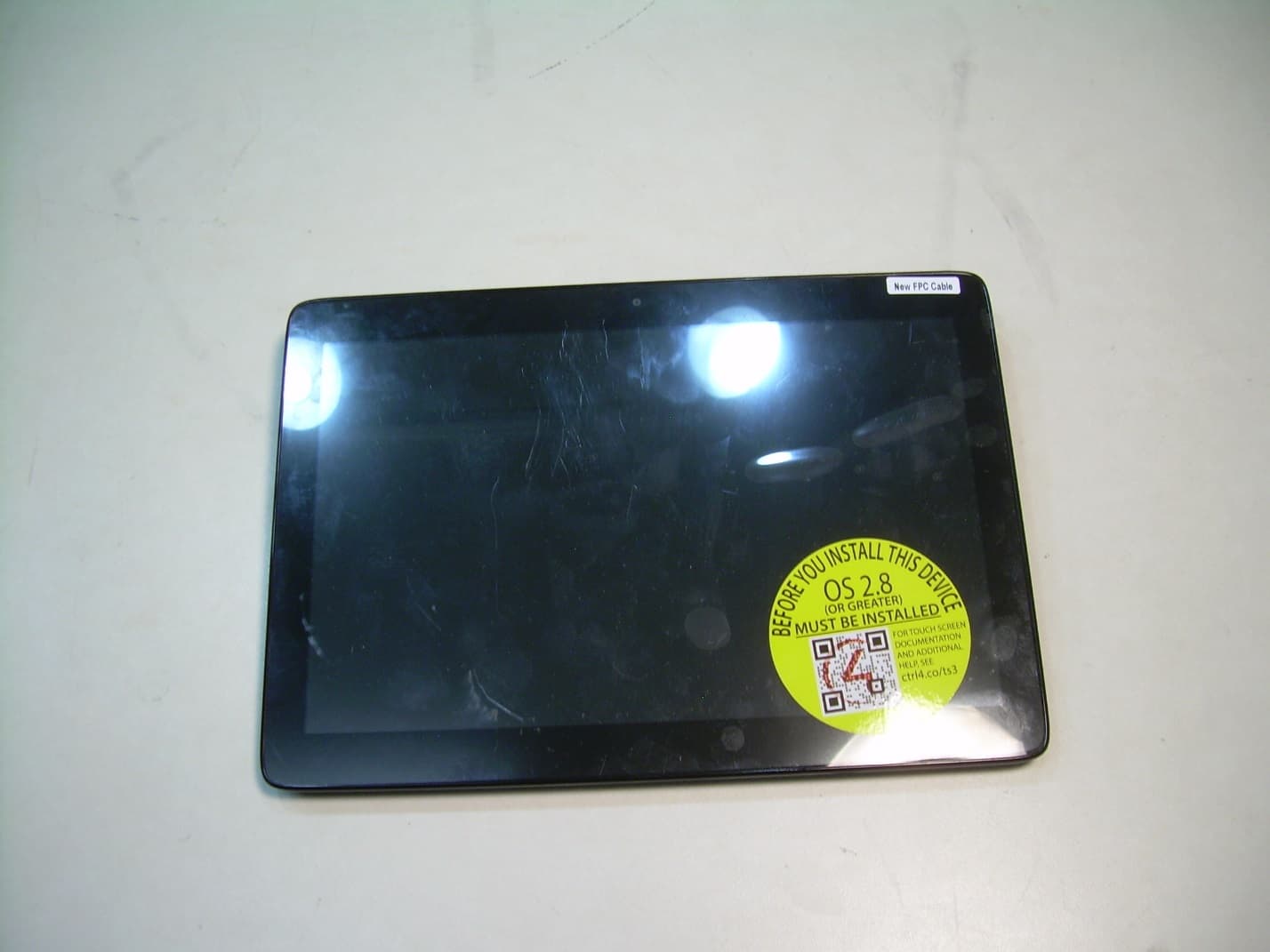
R33C4TT10
Jan 26, 2016Touchscreen Display for home automation system
Equipment Class
DTS - Digital Transmission System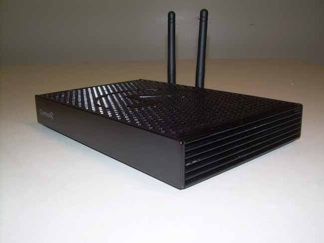
R33C4EA1
Jan 25, 2016Controller for home automation system
Equipment Class
DTS - Digital Transmission System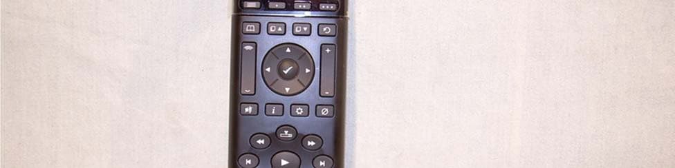
R33C4SR260
Mar 18, 2015Remote control
Equipment Class
DTS - Digital Transmission System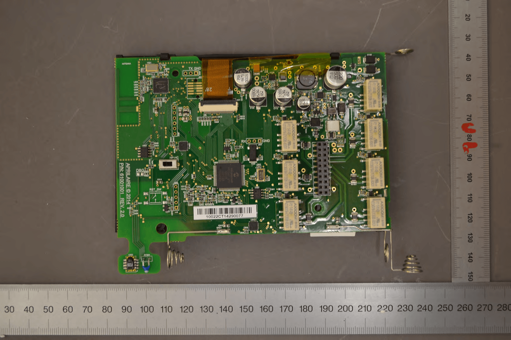
R33C4THERM
Feb 09, 2015THERMOMETER
Equipment Class
DTS - Digital Transmission System
R33C4WMB
Jun 04, 2013C4-WMB-B
Equipment Class
DTS - Digital Transmission System