R33C4EA1Controller for home automation system
Snap One, LLC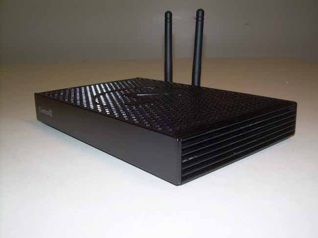
Click to zoom
Application Details
- Equipment Class
- DTS - Digital Transmission System
- Date of Grant
- Jan 25, 2016
- Application Purpose
- Original Equipment
- Date of Application
- Jan 24, 2016
- Equipment Note
- Controller for home automation system
- Frequency Range
- 2405.00000000 - 2475.00000000
- Company
- Snap One, LLC
- Country
- United States
Documents & Files
Document Text
Text extracted from the exhibit documents filed with the FCC. Open a document above to read the original.
Users Manual
EA1 Controller Installation Guide Supported model • C4-EA1 Entertainment and Automation Controller, 1 Zone Introduction The economical Control4® EA1 Controller in the Entertainment and Automation line of controllers provides ways to control lights, home theaters, audio and video, and other devices controlled by infrared (IR), IP, or serial connections. The controller has a fast processor, improved WiFi, HDMI® for audio and video, ZigBee radio, and an expansion module. This controller is perfect for apartments, single rooms, smaller homes, and first-time installations. The EA1 Controller mounts easily on a wall behind the TV. The controller also includes extensive media management for audio and video content: CDs, DVDs, Blu-ray discs, digital media stored on connected devices, and streaming audio services such as Rhapsody and TuneIn. Use a USB or NAS (network-attached storage) drive to store music and photos. After you install and configure the controller with other Control4 devices, your customers can control their system using the On-Screen Navigator, Control4 apps, system remote controls, touch screens, or other Control4-supported interface devices (sold separately). Box contents The following items are included in the EA1 Controller box: • EA1 Controller • AC power cord • IR emitters (4) • Warranty card Accessories available for purchase • EA1 Wall-Mount Bracket (C4-XXXX) • Rack Mount Kit (C4-1URMK1B-B or C4-1URMK2B-B) • Control4 3.5 mm to DB9 Serial Cable (C4-CBL3.5-DB9B) Warnings Caution! To reduce the risk of electrical shock, do not expose this apparatus to rain or moisture. AVERTISSEMENT ! Pour réduire le risque de choc électrique, n’exposez pas cet appareil à la pluie ou à l’humidité. Caution! In an over-current condition on USB, the software disables the output and then blinks the power LED for 10 seconds. When a USB overcurrent fault is detected, you will see the Power LED blink five times per second. After the 10-second blinking period is over, the over- current circuit will be re-enabled. If the over-current condition remains, then the same sequence will repeat itself. AVERTISSEMENT ! Dans une condition de surintensité sur USB ou sortie de contact le logiciel désactive sortie, puis le DEL Power clignote pendant 10 secondes. Quand une erreur de condition de surintensité sur USB est détectée, vous verrez le DEL Power clignoté le DEL cinq fois par seconde et puis quand un défaut de condition de surintensité sur contact est détecté, vous verrez le DEL clignoté 12 fois par seconde. Après la période de 10 secondes de clignotement, le circuit de sur- courant sera réactivé. Si la condition de surintensité reste donc la même, la séquence se répète. For more information, visit the Products pages at dealer.control4.com. Requirements and specifications Note: We recommend using Ethernet instead of WiFi for the best network connectivity. Note: The Ethernet or WiFi network should be installed before starting the EA1 Controller installation. The software required to configure this device is Composer Pro. See the Composer Pro User Guide ( ctrl4.co/cpro-ug) for details. Specifications Model number C4-EA1 Network Ethernet—10/100/1000BaseT compatible (required for controller setup) WiFi—2.4 Ghz 802.11n with WPA2 encryption (supported only when the controller is used in a standalone system or as a secondary controller) Video HDMI 1.4 output; HD 720p/1080p, 50-60 Hz Audio playback formats MP3: 32 kbps to 320 kbps, iTunes Plus, WMA, WMA lossless, Apple lossless, CBR, VBR, AAC, FLAC, and uncompressed WAV and AIFF, Display LED indicators Power requirements 100-240 VAC, 60/50 Hz Power consumption Max: 18W, 61 BTUs/hour Idle: 9W, 30 BTUs/hour Operating temperature 32 ̊ - 104 ̊ F (0 ̊ - 40 ̊ C) Storage temperature 4 ̊ - 158 ̊ F (-20 ̊ - 70 ̊ C) Fan dB level Max: 35 dB IR out 5V 27mA max output IR capture 0-60 KHz USB port 500mA minimum, 600mA maximum Dimensions (H x W x D) 1.13" (29 mm) x 7.5" (191 mm) x 5.0" (127 mm) Weight 1.2 lbs (.54 kg) Shipping weight 2.2 lbs (1.0 kg) Additional resources The following resources are available for more support. • Control4 Knowledgebase: kb.control4.com and Dealer Forums: forums. control4.com • Control4 Technical Support • Control4 website: www.control4.com • Composer Pro documentation in online help or PDF format available on the Dealer Portal under Support: ctrl4.co/docs 6 Connect the power cord to the controller’s power port and then into an electrical outlet. Connect the IR ports/serial ports (optional) The controller provides four IR ports, and ports 1 and 2 can be reconfigured independently for serial communication. If not used for serial, they can be used for IR. Connect a serial device to the controller using the Control4 3.5 mm-to-DB9 Serial Cable (C4-CBL3.5-DB9B, sold separately). 1 The serial ports support baud rates between 1200 to 115200 baud for odd and even parity. The serial ports do not support hardware flow control. 2 See Knowledgebase article #268 ( kb.control4.com/questions/268) for pinout diagrams. 3 To configure a port for serial or IR, make the appropriate connections in your project using Composer Pro. See the Composer Pro User Guide for details. Note: The serial ports can be configured as straight-through or null with Composer Pro. Serial ports by default are configured straight-through and can be changed in Composer by selecting Enable Null-Modem Serial Port (1 or 2). Set up IR emitters Your system may contain third-party products that are controlled through IR commands. 1 Connect one of the included IR emitters to an IR OUT port on the controller. 2 Place the stick-on emitter end onto the IR receiver on the Blu-ray player, TV, or other target device to drive IR signals from the controller to the targets. Set up external storage devices You can store and access media from an external storage device, for example, a network hard drive or USB memory device, by connecting the USB drive to the USB port and configuring or scanning the media in C…
Text truncated - open the document above for the full version.
Cover Letter(s)
11734 South Election Road, Ste. 200 | Salt Lake City, Utah 84020 | www.control4.com | 801.523.3100 phone | 801.523.3199 fax Nemko Canada Inc 303 River Road Ottawa, Ontario, Canada K1V 1H2 Attn: Director of Certification Authority to Act as Agent- FCC On our behalf, I authorize Nemko-CCL, Inc. at 1940 W. Alexander Street, Salt Lake City, UT 84119, to act as our agent in the preparation of this application for equipment certification. I certify that submitted documents properly describe the device or system for which equipment certification is sought. I also certify that each unit manufactured, imported or marketed, as defined in Federal Communications Commission’s regulations will have affixed to it a label identical to that submitted for approval with this application. In signing this letter, Applicant certifies that neither the applicant nor any party to the application is subject to a denial of Federal benefits, that include FCC benefits, pursuant to Section 5301 of the Anti-Drug Abuse Act of 1988, 21 U.S.C. § 862 because of a conviction for possession or distribution of a controlled substance. See 47 CFR 1.2002(b) for the definition of a "party" for these purposes. For instances where our authorized agent signs the application for certification on our behalf, I acknowledge that all responsibility for complying with the terms and conditions for certification, as specified by Nemko Canada Inc. still resides with Control4, located at 11734 S. Election Road, Suite 200, Draper UT, 84020. Dated this 8 th Day of December 20 15 Agency agreement expiration date: December 31, 2016 By: Roger Midgley Signature Printed Title: Sr. Regulatory Compliance Engineer On behalf of : Control4 Corporation Telephone: 801-523-3187
Cover Letter(s)
11734 South Election Road, Ste. 200 | Salt Lake City, Utah 84020 | www.control4.com | 801.523.3100 phone | 801.523.3199 fax MANUFACTURER’S STATEMENT/ATTESTATION Applicant: Control4 Address: 11734S Election Road Suite 200 Draper, UT 84020 Contact Name: Roger Midgley Title: Senior Regulatory Compliance Engineer Brand Name: Control4 Model Number: C4-EA1 FCC ID: R33C4EA1 IC ID: 7848A-C4EA1 Nemko-CCL Test Reports: 294991-1, 294991-2, 294991-3 The manufacturer or responsible party for the equipment tested hereby affirms: a) That he/she has reviewed and concurs that the tests shown in this report are reflective of the operational characteristics of the device for which certification is sought; b) That the device in this test report will be representative of production units; c) That the product will have all of the documented modifications incorporated into the product when manufactured and placed on the market; d) That all changes in hardware and software/firmware to the subject device will be reviewed. e) That any changes impacting the attributes, functionality or operational characteristics documented in this report will be communicated to the body responsible for approving or certifying the subject equipment. Roger Midgley 12/29/2015 Authorized Representative (please print) Signature Date
Cover Letter(s)
11734 South Election Road, Ste. 200 | Salt Lake City, Utah 84020 | www.control4.com | 801.523.3100 phone | 801.523.3199 fax November 2, 2015 Federal Communications Commission 7435 Oakland Mills Road Columbia MD 21046 Subject: Request for Confidentiality FCC ID: R33C4EA1 To Whom It May Concern: Pursuant to the provisions of Sections 0.457 and 0.459 of the Commission’s rules (47 CFR §§ 0.457, 0.459), we are requesting the Commission to withhold the following attachments as confidential document from public disclosure indefinitely. Schematic Diagram Block Diagram Theory of Operation Parts List Above mentioned document contains detailed system and equipment description are considered as proprietary information in operation of the equipment. The public disclosure of above documents might be harmful to our company and would give competitor an unfair advantage in the market. Best Regards Roger Midgley Sr. Regulatory Compliance Engineer
Cover Letter(s)
11734 South Election Road, Ste. 200 | Salt Lake City, Utah 84020 | www.control4.com | 801.523.3100 phone | 801.523.3199 fax January 5, 2016 Deferral of Grant REQUEST LETTER Federal Communications Commission Authorization and Evaluation Division Deferral of Grant Request regarding application for certification of FCC ID: R33C4EA1 Pursuant to Section 0.457 (d) (1) (ii) of the Commission’s Rules, we hereby request the Commission to defer this grant until January 26, 2016: The information in this grant contains trade secrets and proprietary information not customarily released to the public. The public disclosure of these materials may be harmful to the applicant and provide unjustified benefits to its competitors. The applicant understands that pursuant to Section 0.457 of the Rules, disclosure of this application and all accompanying documentation will not be made before the date of the Grant for this application. Sincerely, Roger Midgley Sr. Regulatory Compliance Engineer
External Photos
Front View of the EUT Back View of the EUT Front/Right Side View of the EUT Back/Left Side View of the EUT
ID Label/Location Info
FOR REFERENCE ONLYNOT TO SCALESHEET 2 OF 2 REVSIZEPART # AB 11734 S. Election Road, Suite 200 Draper, UT 84020 Phone: 801-523-3100 Fax: 801-523-3199 TITLE 210-01414 COPYRIGHT 2015 Label, Product ID W/Regulatory Logo, C4-EA1 This device complies with part 15 of the FCC rules and Industry Canada’s license-exempt RSSs. Operation is subject to the following two conditions: (1) This device may not cause harmful interference, and (2) this device must accept any interference received, including interference that may cause undesired operation. CAN ICES-3(B)/NMB-3(B) Model/Modèle/: C4-EA1 ATTENTION: Risque de choc électri que Ne pas ouvri r FCC ID: R33C4EA1 IC: 7848A-C4EA1 Contains FCC ID: PPD-AR5B125 Contains IC: 4104A-AR5B125 Conforms to ANSI/UL STD. 60950-1 Certified to CAN/CSA STD. C22.2 No. 60950-1 Made in China 中国制造 SCALE 1:1DO NOT SCALESHEET 1 OF 2 REVSIZEPART # A DECIMAL: ± 0.508 2 DECIMAL: ± 0.254 3 DECIMAL: ± 0.127 RAD/CHAM: ± 0.508 ANGLE: ± 1.00° TOLERANCES: (ALL DIMENSIONS ARE IN MM) B 1. MATERIAL: COLOR: BLACK PREMIUM COATED, THERMAL TRANSFER POLYESTER PAPER LABEL STOCK SEE PART NUMBER 211-00023 FOR MATERIAL SPECIFICATION AND APPROVED MANUFACTURERS 2. PRINTING: PRINT COLOR: PANTONE 426C BLK (Black), PANTONE 7541 C (White) USE SHEET 2 FOR LABEL PLACEMENT REFERENCE PDF DOCUMENT IS FOR REFERENCE ONLY 3. DOCUMENT SCHEDULE: SHEET 1: ARTWORK SHEET 2: LABEL PLACEMENT THE INFORMATION CONTAINED IN THIS DRAWING AND THE ASSOCIATED CAD DATA IS CONFIDENTIAL, AND IS THE SOLE PROPERTY OF CONTROL4. ANY USE, REPRODUCTION, OR DISCLOSURE - IN WHOLE OR IN PART - WITHOUT WRITTEN PERMISSION FROM CONTROL4 IS PROHIBITED 11734 S. Election Road, Suite 200 Draper, UT 84020 Phone: 801-523-3100 Fax: 801-523-3199 TITLE 210-01414 NO.REVISIONSDATEBY COPYRIGHT 2015 3.0ARTWORK RELEASE01/22/15JBB/CJK AUPDATES FOR PRODUCTION RELEASE.04/24/15JBB BCANADIAN NOTE CHANGE12/22/15MDL NOTES (UNLESS OTHERWISE SPECIFIED): Label, Product ID W/Regulatory Logo, C4-EA1 This device complies with part 15 of the FCC rules and Industry Canada’s license-exempt RSSs. Operation is subject to the following two conditions: (1) This device may not cause harmful interference, and (2) this device must accept any interference received, including interference that may cause undesired operation. CAN ICES-3(B)/NMB-3(B) Model/Modèle/: C4-EA1 ATTENTION: Risque de choc électri que Ne pas ouvri r FCC ID: R33C4EA1 IC: 7848A-C4EA1 Contains FCC ID: PPD-AR5B125 Contains IC: 4104A-AR5B125 Conforms to ANSI/UL STD. 60950-1 Certified to CAN/CSA STD. C22.2 No. 60950-1 Made in China 中国制造
Internal Photos
C4‐EA1 From reports 294991‐2 and ‐3 photograph 10 and 12. Photograph 10 – View of the EUT with Top Removed Showing Top Side of PCB WiFi module 802.15.4 (Zigbee circuitry) Photograph 12 – View of the 802.15.4 Transceiver Circuitry Under the RF Shield
Internal Photos
View of the EUT with Top Removed Showing Top Side of PCB View of the Bottom of the PCB View of the 802.15.4 Transceiver Circuitry Under the RF Shield
RF Exposure Info
11734 South Election Road, Ste. 200 | Salt Lake City, Utah 84020 | www.control4.com | 801.523.3100 phone | 801.523.3199 fax Maximum Permissible Exposure (MPE) Requirement Applicant: Control4 Corporation Control4 Model: C4-EA1 FCC ID: R33C4EA1 This document was prepared using data collected during testing and information provided by the applicant. The maximum power density requirements for the General Public (Uncontrolled Environment) listed in FCC Part 1.1310 were used. The power density is calculated using the following equation. 푃푃 푑푑 = 푃푃 푡푡 퐺퐺 ∗ - 4휋휋푟푟 2 P d = power density in watts P t = transmit power in milliwatts G = numeric antenna gain r = distance between body and transmitter in centimeters ∗ 푃푃 푡푡 퐺퐺 = EIRP The calculated power density of the EUT listed in this application is calculated below. This calculation considers the potential for simultaneous operation, although not typical, of both the transmitter included in this application and the transmitter that was previously certified (WiFi Module) and included in this device. Both transmitters are located in the same unit with the same separation distance. Transceiver #1 (ZigBee) The Maximum source-based time averaged conducted output power is based on the worst case conducted output power as reported in Nemko-CCL,Inc. test report 294991-2.2 section 6.2.4, and declared maximum variation for the output power during manufacturing testing (tune-up procedure) is ± 0.5 dB. Max Transmit Power ERP (dBm): 21.34 Tune- up variance (dB): 0.5 Max Transmit Power EIRP (mW):242.10Max Antenna Gain (dBi):2.00 O perating Frequency (MHz): 2405-2475(N umeric Antenna Gain):1.58 Min Operating Distance (cm):20Duty C ycle (%):100 P ower Density (mW/cm 2 ):0.04816 Limit (mW/cm 2 ):1.0 11734 South Election Road, Ste. 200 | Salt Lake City, Utah 84020 | www.control4.com | 801.523.3100 phone | 801.523.3199 fax Transceiver #2 (WiFi Module) Certified under FCC ID: PPD-AR5B125 The Maximum source-based time averaged conducted output power is based on the worst case conducted output power as reported in Bureau Veritas Consumer Products Services (H.K.) Ltd. test report SA991203E02 section 4, and declared maximum variation for the output power during manufacturing testing (tune-up procedure) is ± 0.5 dB. Combined Power CONCLUSION: Therefore our device complies with the FCC’s RF radiation exposure limits for general population without SAR evaluation. Best Regards Roger Midgley Sr. Regulatory Compliance Engineer Max Transmit Power ERP (dBm): 24.3 Tune- up variance (dB): 2.00 Max Transmit Power EIRP (mW): 676.08Max Antenna Gain (dBi): 2.00 O perating Frequency (MHz):2412-2462 (N umeric Antenna Gain): 1.58 Min Operating Distance (cm): 20Duty C ycle (%):100 P ower Density (mW/cm 2 ): 0.13450 Limit (mW/cm 2 ):1.0 Zigbee P ower Density (mW/cm 2 ):0.04816 WiFi Module P ower Density (mW/cm 2 ):0.13450 Total (mW/cm 2 ): 0.18266 Limit (mW/cm 2 ):1.0 Delta:-0.817
Test Setup Photos
Front View Radiated Disturbance Configuration – Oxford TEC Antenna Back View Radiated Disturbance Configuration – Oxford TEC Antenna Back View Radiated Disturbance Configuration – Cirocomm Technology Antenna Front View Conducted Disturbance Configuration Back View Conducted Disturbance Configuration
Contact Information
Applicant
Roger J Midgley(Principle Compliance Engineer)
Test Firm
Nemko-CCL incThomas Jackson
Technical Specifications
| # | Rule Parts | Frequency Range | Power Output |
|---|---|---|---|
| 1 | 15C | 2.40 GHz - 2.48 GHz | 136.00 mW |
Other Applications from Snap One, LLC
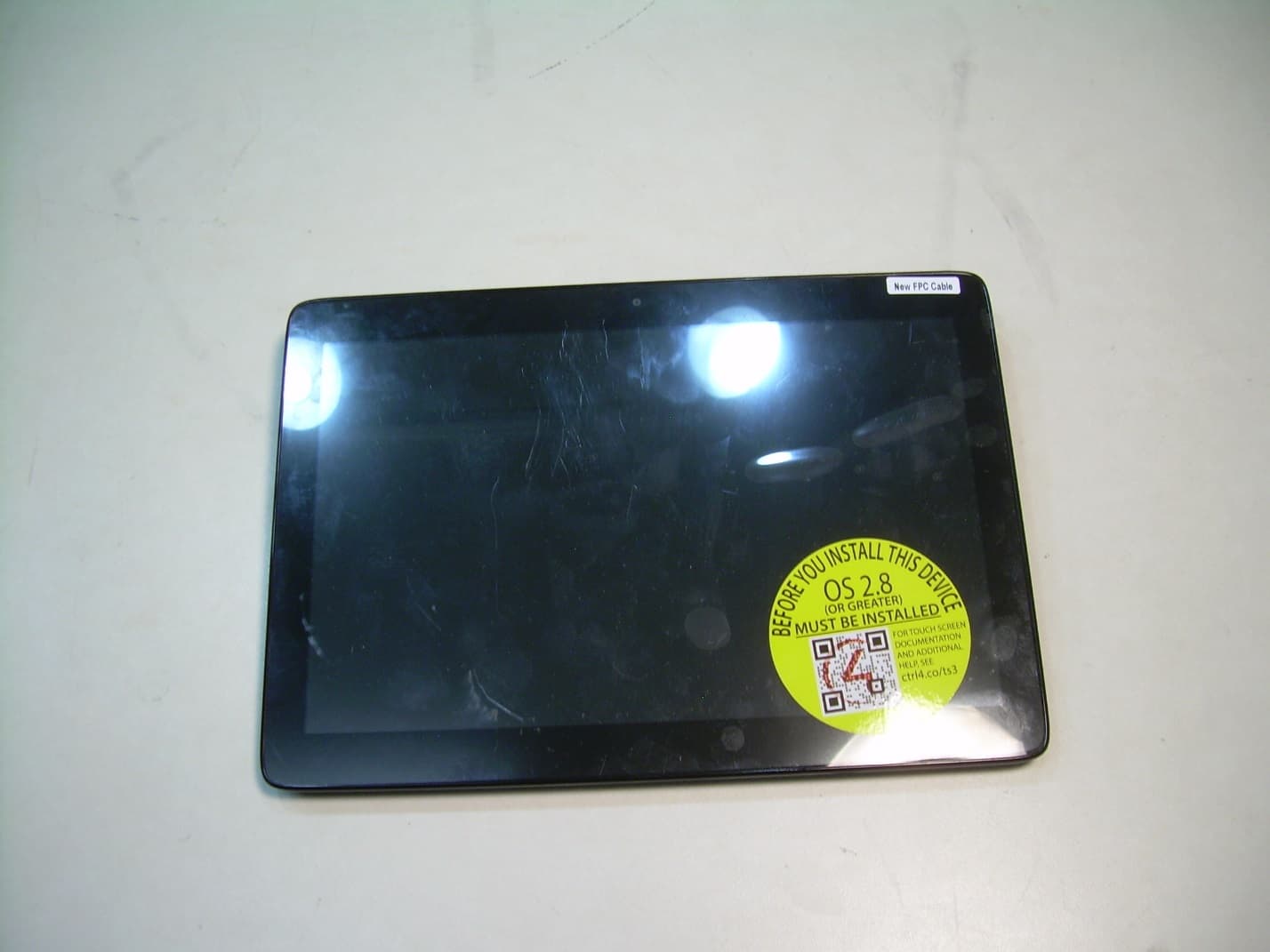
R33C4TT10
Jan 26, 2016Touchscreen Display for home automation system
Equipment Class
DTS - Digital Transmission System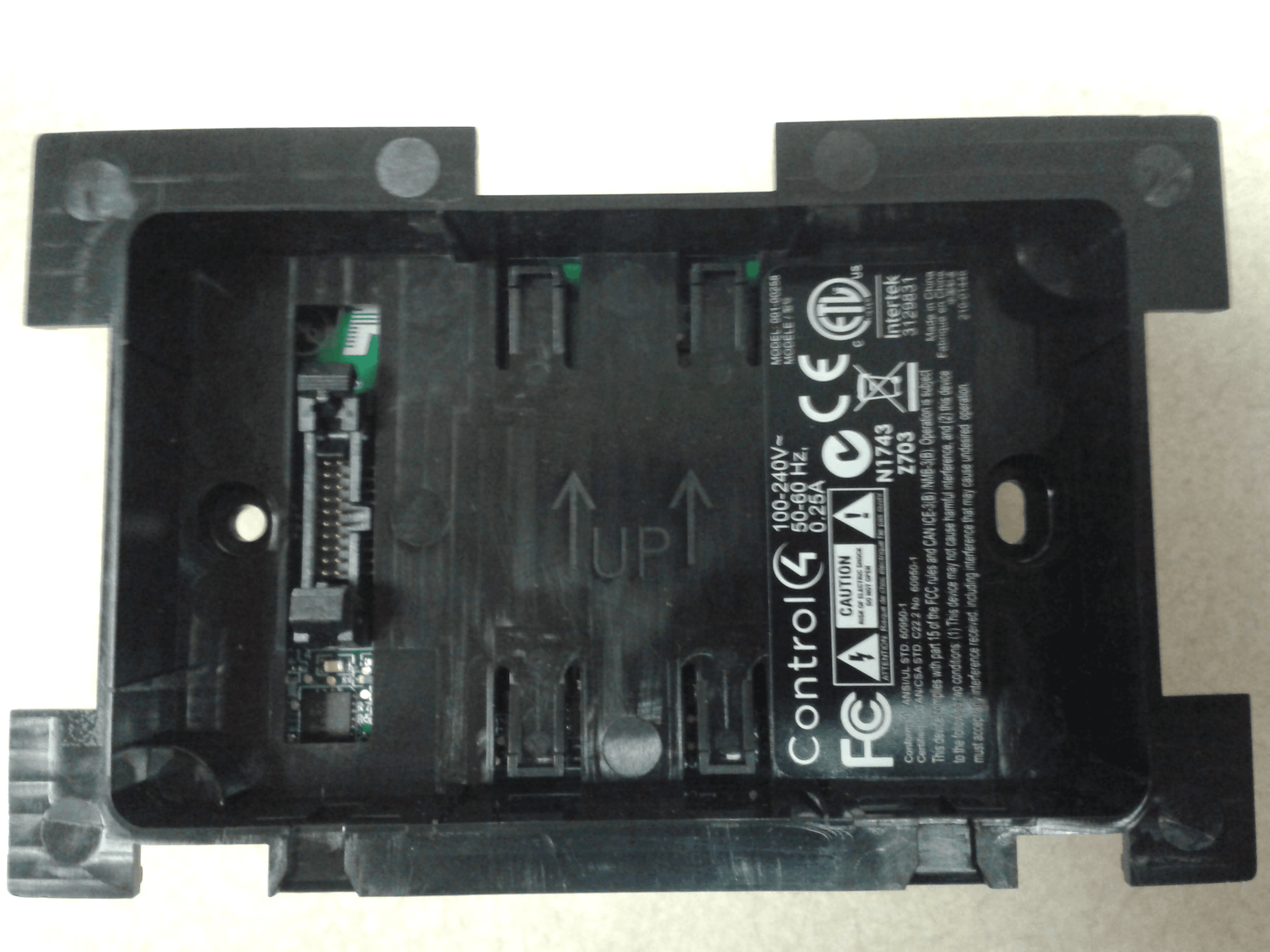
R33C4LGWM
Mar 24, 2015WIFI MODULE
Equipment Class
DTS - Digital Transmission System
R33C4SR260
Mar 18, 2015Remote control
Equipment Class
DTS - Digital Transmission System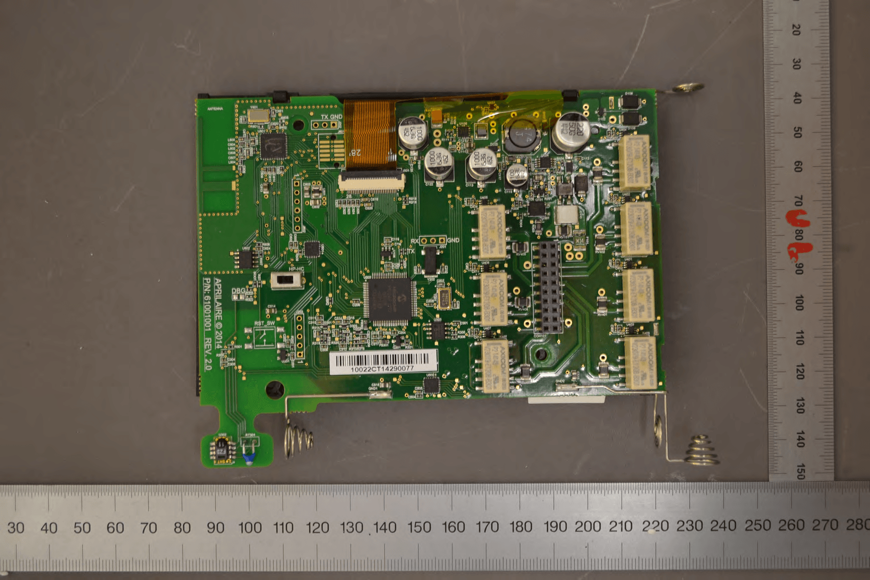
R33C4THERM
Feb 09, 2015THERMOMETER
Equipment Class
DTS - Digital Transmission System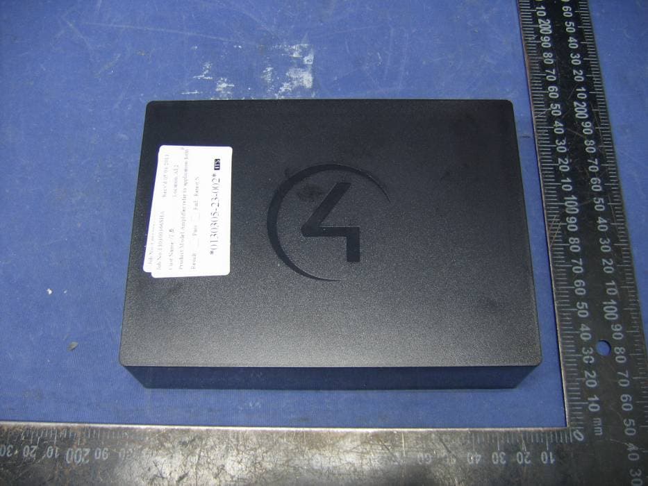
R33C4WMB
Jun 04, 2013C4-WMB-B
Equipment Class
DTS - Digital Transmission System