R33AVMMC11Model AVM-MC1-B Media Controller
Snap One, LLC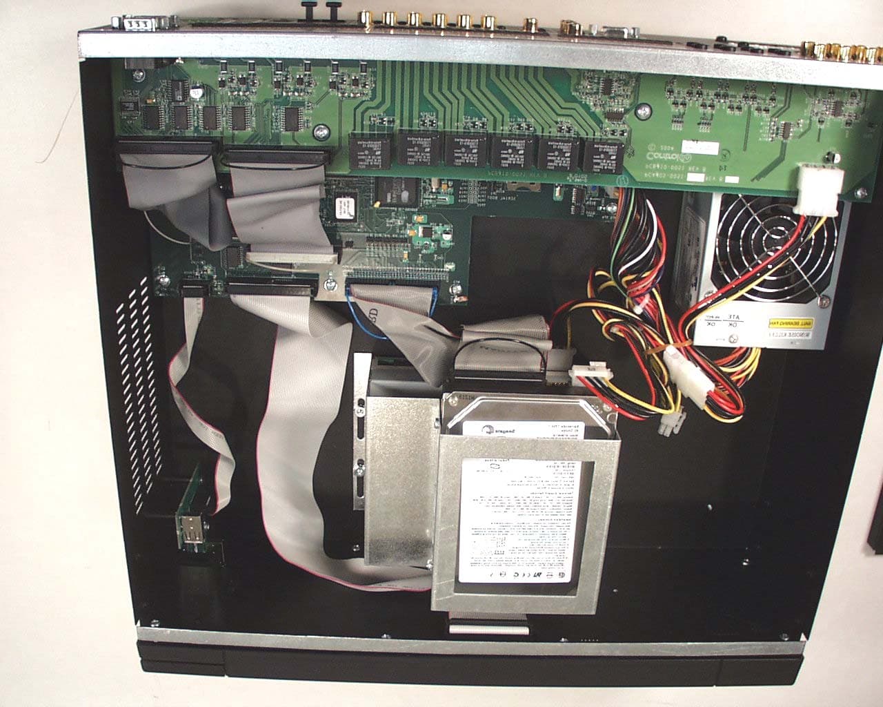
Click to zoom
Application Details
- Equipment Class
- DTS - Digital Transmission System
- Date of Grant
- Feb 07, 2005
- Application Purpose
- Original Equipment
- Date of Application
- Feb 07, 2005
- Equipment Note
- Model AVM-MC1-B Media Controller
- Frequency Range
- 2400.00000000 - 2483.50000000
- Company
- Snap One, LLC
- Country
- United States
Documents & Files
Document Text
Text extracted from the exhibit documents filed with the FCC. Open a document above to read the original.
Users Manual
Disclaimer Control4 ® makes no representations or warranties with respect to the contents or use of this manual, and specifically disclaims any express or implied warranties of merchantability or fitness for any particular purpose. Control4 reserves the right to revise this publication and to make changes to its content, at any time, without obligation to notify any person or entity of such revisions or changes. Control4 makes no representations or warranties with respect to any Control4 software, and specifically disclaims any express or implied warranties of merchantability or fitness for any particular purpose. Control4 reserves the right to make changes to any and all parts of Control4 software and hardware, at any time, without any obligation to notify any person or entity of such changes. Trademarks Control4 and the Control4 logo are registered trademarks of Control4 Corporation. Other product and company names mentioned in this document may be the trademarks or registered trademarks of their respective owners. Legal Notice Fraunhofer IIS and Thomson. MPEG Layer-3 audio coding technology license from Fraunhofer IIS and Thomson. Supply of this product does not convey a license nor imply any right to distribute content created with this product in revenue-generating broadcast systems (terrestrial, satellite, cable, and /or other distribution channels), streaming applications (via Internet, intranets, and/or other networks), other content distribution systems (pay-audio or audio-on-demand applications, and the like) or on physical media (compact discs, digital versatile discs, semiconductor chips, hard drives, memory cards, and the like). Gracenote. Music recognition technology and related data are provided by Gracenote. Gracenote is the industry standard in music recognition technology and related content delivery. For more information visit www.gracenote.com. Copyright Copyright © 2004-2005 Control4. All rights reserved. No part of this publication may be reproduced, photocopied, stored on a retrieval system, or transmitted without the express written consent of the publisher. Contact Us Control4 Corporation 11734 S. Election Road, Suite 200 Salt Lake City, UT 84020 USA http://www.control4.com Media Controller Installation and User Guide Part Number: 21-0050 Rev A Draft 7 (in progress) Hardware Model Number: AVM-MC1-B i Contents PrefaceAbout This Guide........................................... 1 Notes, Tips, Cautions, and Warnings .... 1 Additional Resources ............................. 2 Chapter 1Introduction to Media Controller .................... 3 Role in a Control4 System ..................... 3 Features and Benefits............................ 4 Requirements ........................................ 4 Supported Devices ................................ 5 What’s in the Box ................................... 5 About the Media Controller .................... 5 Front View with Door Opened........... 7 Back View ......................................... 8 Chapter 2Set Up the System ...................................... 11 Plan Your Equipment Layout ............... 11 Physical and Logical Connections .. 12 Home Network Requirements......... 12 Sample Setup Diagrams................. 13 Determine Best Video Option ......... 16 Use a Worksheet ............................ 16 Connect to a Monitor or TV.................. 19 Connect to the Network ....................... 20 Connect Devices.................................. 20 Use the Plugable Terminal Blocks.. 20 Connect Wires to a Configurable Serial Port.................. 21 Add IR Receiver Capabilities to Remote Locations........................... 22 Set Up IR-Signal Generation to Control Third-Party Devices............ 23 Use Video Sense Loop to Add On/Off Sensing........................ 23 ii Connect AV Devices to One Another .. 23 Relocate the WiFi Antenna .................. 24 Set Up Logical Connections ................ 24 Check Setup Using On-Screen Display25 Chapter 3Use Media Controller................................... 27 User Interfaces .................................... 27 On-Screen Navigator ...................... 27 System Remote Control with LCD .. 28 Media Controller Front Display ....... 29 View or Edit Setup Information ............ 30 Play a CD............................................. 30 Choose a Playlist Option ..................... 31 Understand Future Feature Support .... 32 Chapter 4Warranty and FCC Information.................... 33 Warranty .............................................. 33 Limited Hardware Warranty ............ 33 Hardware Warranty Terms ............. 34 Software Agreement ....................... 37 FCC Information .................................. 38 FCC Interference Statement........... 38 FCC Caution ................................... 39 1 PREFACE About This Guide Notes, Tips, Cautions, and Warnings Media Controller Installation and User Guide Note, Tip, Caution, and Warning paragraphs draw your attention to safe practices and additional information which may help you avoid losing data or time. NOTE: These contain notes on related information about the current topic. TIP: These provide tips that may save you time or effort. CAUTION! These provide specific cautions about improper use of equipment or failure to follow safety instructions that may cause bodily injury. DO NOT IGNORE A CAUTION! WARNING! These provide specific warnings about improper use of equipment or failure to follow safety instructions that may cause data loss or equipment damage. DO NOT IGNORE A WARNING! 2 Additional Resources The following resources are available to provide you with additional support. `Your authorized Control4 representative or reseller. ` Control4 Web Site: http://www.Control4.com/ 3 CHAPTER 1Introduction to Media Controller This chapter introduces a Control4 home system and explains the important role a Media Controller plays in that system. Role in a Control4 System Control4 systems are uniqu…
Text truncated - open the document above for the full version.
Internal Photos
Internal View of the EUT Component Side of the Radio Card Trace Side of the Radio Card
Operational Description
AVM-MC1-B Media Controller Operational Description The AVM-MC1-B Media Controller is a microprocessor-based digital audio server with full home automation control features. The system uses a CD-RW drive to digitally record audio CD’s onto a hard drive. It can then serve multiple independent audio streams over Ethernet and WiFi networks as well as from three stereo analog audio outputs and one digital audio (TOSLINK) output. It can accept audio inputs from three line level stereo analog inputs and one digital audio input (TOSLINK). The user interacts with the Media Controller using a 2.4 GHZ (802.15.4) wireless remote control and video user interface. The video is output in one of four video formats including NTSC/PAL composite, S-video, Component (YPbPr), and VGA. The user also interacts with the Media Controller via front panel LCD graphics display, four buttons and a rotary encoder. The Media Controller’s home automation features include IR inputs and outputs, Relay’s, Contact Sense inputs, Composite video sense inputs, and serial ports. TCP/IP Networked devices are controlled over 10/100baseT Ethernet and 802.11b/g WiFi. Other wireless devices are controlled using an integrated a 2.4 GHZ (802.15.4) radio. The IR outputs are 3.5mm phone jacks intended to drive IR LED extension cables. The cable ends have a small housing containing and IR LED and fitted with and adhesive strip allowing them to be mounted over the IR input windows of equipment to be controlled by the Media Controller. The relay outputs have Normally Open, Normally Closed and Common terminals available on terminal blocks and are intended to switch low voltage devices such as gas fireplaces, or sprinklers. Contact inputs can allow switch closures or logic level signals to be sensed by the Media Controller. These inputs are intended to accept input from devices like motion sensors or door closure switches. The serial ports can support RS232, RS422 and RS485 standards. WiFi communications are implemented using a pre-approved FCC compliant USB WiFi adapter.
RF Exposure Info
1 MPE Calculations R33AVMMC11 2 1.0 SCOPE_________________________________________________________3 2.0 REVISION LEVEL_______________________________________________4 3.0 REFERENCE DOCUMENTS______________________________________4 4.0 CALCULATIONS________________________________________________5 5.0 CONCLUSION___________________________________________________6 3 1.0 SCOPE: This Report Demonstrates Evaluation and Compliance for Human Exposure to Radiofrequency Electromagnetic Fields as Outlined by the Federal Communications Commission Office of Engineering and Technology Bulletin 65. 2.0 REVISION LEVEL: DATE COMMENTS REVISION 1/21/2005 Created. 1.0 3.0 REFERANCE DOCUMENTS: (A) Limits for Maximum Permissible Exposure (MPE). Code of Federal Regulations Title 47, Volume 1, Section 1.1310. (B) Evaluating Compliance with FCC Guidelines for Human Exposure to Radiofrequency Electromagnetic Fields. OET Bulletin 67 Edition 97-01. 4.0 CALCULATIONS: The AVM-MC1-B utilizes a low power 2.4 GHz radio located approx 1 cm behind the front panel plastic. The following worst case emissions are based on a PPt (Peak Power Total) measurement of 12.8 dBm. And the worst case antenna gain on axis is found to be 3.64 dBi. Total radiated power at the Transmitter: A) Pt = 12.8 dBm + 3.64 dBi = 16.4 dBm EIRP 16.4 dBm EIRP = .0441 Watts. (44.1mW) Power density at a distance of 10cm from the antenna is: B) S = EIRP/4π∙r 2 Where S is Power density in units of mW/cm 2 and EIRP is Equivalent Isotropic Radiated Power in units of mW and r is distance to the center of radiation of the antenna in units of cm 4 S = 44.1mW/(4 π (10cm) 2 ) = .00351mW/cm 2 5.0 CONCLUSION: Based on the FCC Limits for Maximum Permissible Exposure (MPE) given in Table 1 of reference document (A) this device falls under the required limits.
Test Report
TEST REPORT FROM: COMMUNICATION CERTIFICATION LABORATORY 1940 W. Alexander Street Salt Lake City, Utah 84119-2039 Type of Report: Certification TEST OF: AVM-MC1-B FCC ID: R33AVMMC11 To FCC PART 15, Subpart C (15.203, 15.207, 15.247) Test Report Serial No: 73-8052 Applicant: Control4 11734 S. Election Drive, Suite 200 Draper, UT 84020 Date of Test: January 19, 2005 Issue Date: January 20, 2005 Equipment Receipt Date: January 19, 2005 COMMUNICATION CERTIFICATION LABORATORY TEST REPORT: 73-8052 FCC ID#: R33AVMMC11 Page 2 of 52 CERTIFICATION OF ENGINEERING REPORT This report has been prepared by Communication Certification Laboratory to document compliance of the device described below with the requirements of Federal Communications Commission (FCC) Part 15, Subpart C, Sections 15.203, 15.207, and 15.247. This report may be reproduced in full, partial reproduction may only be made with the written consent of the laboratory. The results in this report apply only to the sample tested. - Applicant: Control4 - Manufacturer: Control4 - Brand Name: Control4 - Model Number: AVM-MC1-B - FCC ID Number: R33AVMMC11 On this 20 th day of January 2005, I, individually, and for Communication Certification Laboratory, certify that the statements made in this engineering report are true, complete, and correct to the best of my knowledge, and are made in good faith. Although NVLAP has recognized that the Communication Certification Laboratory EMC testing facilities are in good standing, this report must not be used to claim product certification, approval, or endorsement by NVLAP, NIST, or any agency of the federal government. COMMUNICATION CERTIFICATION LABORATORY Tested by: Norman P. Hansen EMC Technician COMMUNICATION CERTIFICATION LABORATORY TEST REPORT: 73-8052 FCC ID#: R33AVMMC11 Page 3 of 52 TABLE OF CONTENTS PAGE SECTION 1.0 CLIENT INFORMATION .................................4 SECTION 2.0 EQUIPMENT UNDER TEST (EUT) ..........................5 SECTION 3.0 TEST SPECIFICATION, METHODS & PROCEDURES ..........10 SECTION 4.0 OPERATION OF EUT DURING TESTING ...................16 SECTION 5.0 SUMMARY OF TEST RESULTS ...........................18 SECTION 6.0 MEASUREMENTS, EXAMINATIONS AND DERIVED RESULTS .....19 APPENDIX 1 TEST PROCEDURES AND TEST EQUIPMENT ..................35 APPENDIX 2 PHOTOGRAPHS .........................................44 COMMUNICATION CERTIFICATION LABORATORY TEST REPORT: 73-8052 FCC ID#: R33AVMMC11 Page 4 of 52 SECTION 1.0 CLIENT INFORMATION 1.1 Applicant: Company Name: Control4 11734 S. Election Drive, Suite 200 Draper, UT 84020 Contact Name: Steve Coffin Title: Senior Hardware Engineer 1.2 Manufacturer: Company Name: Control4 11734 S. Election Drive, Suite 200 Draper, UT 84020 Contact Name: Steve Coffin Title: Senior Hardware Engineer COMMUNICATION CERTIFICATION LABORATORY TEST REPORT: 73-8052 FCC ID#: R33AVMMC11 Page 5 of 52 SECTION 2.0 EQUIPMENT UNDER TEST (EUT) 2.1 Identification of EUT: Brand Name: Control4 Model Name or Number: AVM-MC1-B Serial Number: None Options Fitted: N/A Country of Manufacture: U.S.A. 2.2 Description of EUT: The AVM-MC1-B is a home theater controller with digital audio and a home control feature. The AVM-MC1-B Media Controller digitally stores the music collections of everyone in the family and delivers simultaneous audio streams over a wired or wireless home network. The Media Controller provides Composite video out, S-video, VGA, or Component video out. The AVM-MC1-B has 6 relay and 6 contact input/outputs for controlling other home theater components. An Ethernet port is provided for connection to the Internet or network. An 802.15.4 Zigbee radio is used for remote programming and control. This report covers the 802.15.4 Zigbee radio subject to FCC Subpart C, §15.247. The digital circuitry subject to FCC Subpart B is to be covered in separate testing and report. The 802.15.4 transceiver uses 15 channels in the 2400 to 2483.5 MHz band. The individual channels are shown in the following plots. COMMUNICATION CERTIFICATION LABORATORY TEST REPORT: 73-8052 FCC ID#: R33AVMMC11 Page 6 of 52 dBm 11 1 -9 -19 -29 -39 -49 -59 -69 -79 -89 Control4 73-8019 Trace A Start: 2.402500 GHzStop: 2.427500 GHz Res BW: 100 kHzVid BW: 300 kHzSweep: 20 ms 01/19/2005 3:57:50 PMHP8566B Trace ALower 5 channels 1 1 2.405075 GHz 3.0000 dBm 2 2 2.410175 GHz 1.3000 dBm 3 3 2.415200 GHz 1.3000 dBm 4 4 2.420200 GHz 1.3000 dBm 5 5 2.425300 GHz 1.6000 dBm dBm 11 1 -9 -19 -29 -39 -49 -59 -69 -79 -89 Control4 73-8019 Trace A Start: 2.427500 GHzStop: 2.452500 GHz Res BW: 100 kHzVid BW: 300 kHzSweep: 20 ms 01/19/2005 3:56:10 PMHP8566B Trace AMiddle 5 channels 1 1 2.430075 GHz 2.8000 dBm 2 2 2.435225 GHz 2.0000 dBm 3 3 2.440325 GHz 1.6000 dBm 4 4 2.445350 GHz 2.6000 dBm 5 5 2.450525 GHz 1.7000 dBm COMMUNICATION CERTIFICATION LABORATORY TEST REPORT: 73-8052 FCC ID#: R33AVMMC11 Page 7 of 52 dBm 11 1 -9 -19 -29 -39 -49 -59 -69 -79 -89 Control4 73-8019 Trace A Start: 2.452500 GHzStop: 2.477500 GHz Res BW: 100 kHzVid BW: 300 kHzSweep: 20 ms 01/19/2005 3:54:04 PMHP8566B Trace AUpper 5 channels 1 1 2.455150 GHz 2.5000 dBm 2 2 2.460300 GHz 2.3000 dBm 3 3 2.465400 GHz 1.3000 dBm 4 4 2.470550 GHz 2.6000 dBm 5 5 2.475675 GHz 2.1000 dBm COMMUNICATION CERTIFICATION LABORATORY TEST REPORT: 73-8052 FCC ID#: R33AVMMC11 Page 8 of 52 2.3 EUT and Support Equipment: The FCC ID numbers for all the EUT and support equipment used during the test (including inserted cards) are listed below: Brand Name Model Number Serial No. FCC ID Number Description Name of Interface Ports / Interface Cables BN: Control4 MN: AVM-MC1-B (Note 1) R33AVMMC11 Media Controller See Section 2.4 BN: TRENDnet MN: TE100-S8P SN: 0243C3A16540 (Note 3) Verification 8 port LAN hub Ethernet 1-8/Cat 5 cable w/RJ45 connectors (Note 2) BN: HP MN: Pavillion (Note 3) DoC Laptop Computer Ethernet/Cat 5 cable Note: (1) EUT (2) Interface port connected to EUT (See Section 2.4) (3) Located below the turntable The support equipment listed above was not modifie…
Text truncated - open the document above for the full version.
Test Setup Photos
Front View Radiated Disturbance Worst Case Configuration Back View Radiated Disturbance Worst Case Configuration Front View Conducted Disturbance Worst Case Configuration Back View Conducted Disturbance Worst Case Configuration
Contact Information
Applicant
Roger J Midgley(Principle Compliance Engineer)
Test Firm
Communication Certification Lab.Scott Earl
Technical Specifications
| # | Rule Parts | Frequency Range | Power Output |
|---|---|---|---|
| 1 | 15C | 2.40 GHz - 2.48 GHz | 5.89 mW |
Other Applications from Snap One, LLC
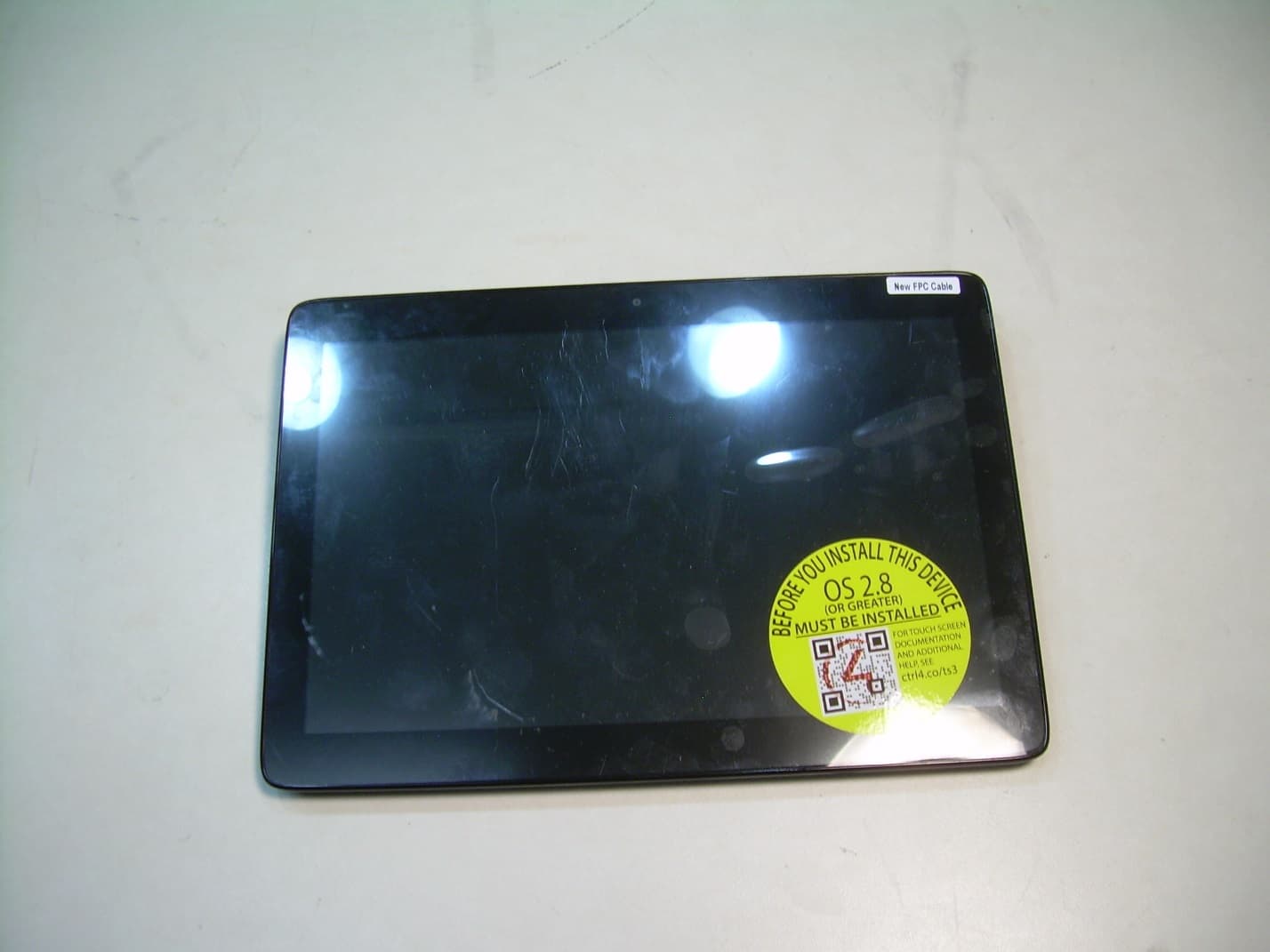
R33C4TT10
Jan 26, 2016Touchscreen Display for home automation system
Equipment Class
DTS - Digital Transmission System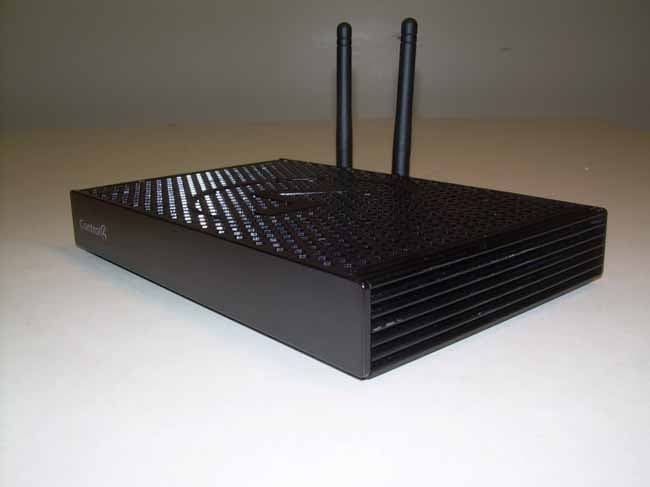
R33C4EA1
Jan 25, 2016Controller for home automation system
Equipment Class
DTS - Digital Transmission System
R33C4LGWM
Mar 24, 2015WIFI MODULE
Equipment Class
DTS - Digital Transmission System
R33C4SR260
Mar 18, 2015Remote control
Equipment Class
DTS - Digital Transmission System
R33C4THERM
Feb 09, 2015THERMOMETER
Equipment Class
DTS - Digital Transmission System