R33AVMTUN1X1Multi-Tuner AVM-TUN1-B
Snap One, LLC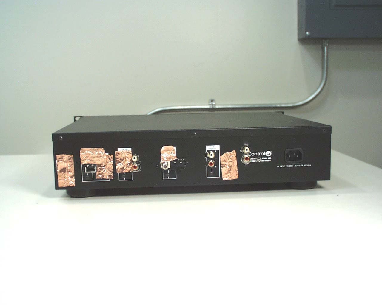
Click to zoom
Application Details
- Equipment Class
- DTS - Digital Transmission System
- Date of Grant
- Jun 22, 2005
- Application Purpose
- Original Equipment
- Date of Application
- Jun 22, 2005
- Equipment Note
- Multi-Tuner AVM-TUN1-B
- Frequency Range
- 2400.00000000 - 2483.50000000
- Company
- Snap One, LLC
- Country
- United States
Documents & Files
Document Text
Text extracted from the exhibit documents filed with the FCC. Open a document above to read the original.
Users Manual
28 Limited Software Warranty, Liability, and Remedy Important: This Control4 Software Limited Warranty shall cover all software that is provided to you, the customer, as part of the Control4 product, including any operation system software. The Remedies provided in this document are your sole and exclusive remedies. In no event shall Control4 be liable for any direct, indirect, special, incidental, or consequential damages (including lost profit), whether based on warranty, contract, tort, or any other legal theory. In no case shall Control4's liability exceed the purchase price for the software and/or product. The limitations set forth above will apply regardless of whether you accept the software. Regulatory Compliance This product complies with standards established by the following regulatory bodies: Federal Communications Commission (FCC) Industry Canada FCC FCC ID: R33AVMTUN1X1 This device complies with Part 15 of the FCC Rules. Operation is subject to the following two conditions: (1) This device may not cause harmful interference, and (2) this device must accept any interference received, including interference that may cause undesired operation. This equipment has been tested and found to comply with the limits for a Class B digital device, pursuant to Part 15 of the FCC Rules. These limits are designed to provide reasonable protection against harmful interference in a residential installation. This equipment generates uses and can radiate radio frequency energy and, if not installed and used in accordance with the instructions, may cause harmful 29 interference to radio communications. However, there is no guarantee that interference will not occur in a particular installation. If this equipment does cause harmful interference to radio or television reception, which can be determined by turning the equipment off and on, the user is encouraged to try to correct the interference by one of the following measures: ` Reorient or relocate the receiving antenna. `Increase the separation between the equipment and receiver. `Connect the equipment into an outlet on a circuit different from that to which the receiver is connected. `Consult the dealer or an experienced radio/TV technician for help. Any changes or modifications not expressly approved by the party responsible for compliance could void the user's authority to operate this equipment. Industry Canada This Class B digital apparatus complies with Canada ICES-003. Cet appareil numérique de la classe B est conforme à la norme NMB-003 du Canada.
Block Diagram
AVM-TUN1-B Multi-Tuner Block Diagram Front Panel Expansion Slot Power Supply +12V +5V LCD Control +5V Serial Microcontroller LCD Display Switches, LED’s, Speaker Zigbee Radio Microcontroller CPLD RAM Ethernet Addr, Data, Cntl LED’s, XM Radio Module DAC Antenna Digital Audio Stereo Analog Audio Front Panel Reset Switch Reset AM/FM Radio AM/FM PLL Stereo Decoder RDS Decoder AM/FM Radio AM/FM PLL Stereo Decoder RDS Decoder AM/FM Common Front End AM/FM Tuner 1AM/FM Tuner 2 XM Antenna XM Stereo Line Out AM Antenna FM Antenna Tuner 1 AM, FM Stereo Line Out Tuner 2 AM, FM Stereo Line Out Ethernet Main Board Control, Status
Cover Letter(s)
11734 South Election Drive Suite 200 Draper, Utah 84020 (801) 523-3100 To: Federal Communications Commission Date: 5/18/05 445 12 th Street, SW Washington, DC 20554 Re: Non disclosure Request for FCC ID: R33AVMTUN1X1 We are requesting that the following documents be held and treated as confidential and proprietary information. These materials contain technical trade secret information and should be guarded from competitors as stated under the Code of Federal Regulations Title 47 Section 0.459 (3), (4) and (5). 1) All AVM-TUN1-B Schematic diagrams Steve Coffin Senior Electrical Engineer Control4 Corporation
External Photos
Front View of the EUT Back View of the EUT Note that the rear panel of the EUT was a rear panel from another device. Openings were drilled for connectors and other openings for connectors were covered with copper tape to achieve a rear panel that replicates one that has been manufactured for the EUT.
Internal Photos
Internal View of the EUT Top Side of the Main PCB Bottom Side of the Main PCB Component Side of the Front Panel PCB with Zigbee Radio Component Side of the Front Panel PCB with Zigbee Radio Removed Trace Side of the Front Panel PCB Component Side of the Zigbee Radio Trace Side of the Zigbee Radio Component Side of the Reset PCB Trace Side of the Reset PCB Component Side of the Power Supply Trace Side of the Power Supply
Operational Description
11734 South Election Drive Suite 200 Draper, Utah 84020 (801) 523-3100 AVM-TUN1-B Multi-Tuner Functional Description The AVM-TUN1-B Multi-Tuner is a microprocessor controlled tuner intended for use in home audio applications. The device is housed in a 2 RU 17 inch metal, rack mountable, chassis and is powered by a universal (90-250 VAC 50/60Hz) power supply. There are two AM/FM radio tuners and an optional XM radio tuner integrated into the AVM- TUN1-B. Each tuner provides line-level out stereo outputs. The AVM-TUN1-B also has 10/100 BaseT Ethernet and 802.15.4 Zigbee network communications capabilities. All of the tuner’s settings are controllable through the network connections making this amplifier useful in full home automation installations. Full control over display, status, channel tuning and muting are controlled over (either or both) zigbee (802.15.4) or Ethernet communications (TCP/IP). Users may also control the tuner via the LCD graphic front panel, soft buttons and an encoder wheel.
RF Exposure Info
1 MPE Calculations R33AVMTUN1X1 2 1.0 SCOPE_________________________________________________________3 2.0 REVISION LEVEL_______________________________________________4 3.0 REFERENCE DOCUMENTS______________________________________4 4.0 CALCULATIONS________________________________________________5 5.0 CONCLUSION___________________________________________________6 3 1.0 SCOPE: This Report Demonstrates Evaluation and Compliance for Human Exposure to Radiofrequency Electromagnetic Fields as Outlined by the Federal Communications Commission Office of Engineering and Technology Bulletin 65. 2.0 REVISION LEVEL: DATE COMMENTS REVISION 5/18/2005 Created. 1.0 3.0 REFERANCE DOCUMENTS: (A) Limits for Maximum Permissible Exposure (MPE). Code of Federal Regulations Title 47, Volume 1, Section 1.1310. (B) Evaluating Compliance with FCC Guidelines for Human Exposure to Radiofrequency Electromagnetic Fields. OET Bulletin 67 Edition 97-01. 4.0 CALCULATIONS: The AVM-TUN1-B utilizes a low power 2.4 GHz radio located approx 1 cm behind the front panel plastic. The following worst case emissions are based on a PPt (Peak Power Total) measurement of 12.8 dBm. And the worst case antenna gain on axis is found to be 3.64 dBi. Total radiated power at the Transmitter: A) Pt = 12.8 dBm + 3.64 dBi = 16.4 dBm EIRP 16.4 dBm EIRP = .0441 Watts. (44.1mW) Power density at a distance of 10cm from the antenna is: B) S = EIRP/4π·r 2 Where S is Power density in units of mW/cm2 and EIRP is Equivalent Isotropic Radiated Power in units of mW and r is distance to the center of radiation of the antenna in units of cm S = 44.1mW/(4 π (10cm) 2 ) = .00351mW/cm 2 4 5.0 CONCLUSION: Based on the FCC Limits for Maximum Permissible Exposure (MPE) given in Table 1 of reference document (A) this device falls under the required limits.
Test Report
COMMUNICATION CERTIFICATION LABORATORY 1940 West Alexander Street Salt Lake City, UT 84119 801-972-6146 Certification Test Report TEST OF: AVM-TUN1-B FCC ID: R33AVMTUN1X1 To FCC PART 15, Subpart C (15.203, 15.207, 15.247) Test Report Serial No: 73-8108 Applicant: Control4 11734 S. Election Road, Suite 200 Draper, UT 84020 U.S.A. Date of Test: May 11, 2005 Issue Date: May 12, 2005 Equipment Receipt Date: May 11,2005 Accredited Testing Laboratory By: NVLAP Lab Code 100272-0 COMMUNICATION CERTIFICATION LABORATORY TEST REPORT: 73-8108 FCC ID#: R33AVMTUN1X1 Page 2 of 62 CERTIFICATION OF ENGINEERING REPORT This report has been prepared by Communication Certification Laboratory to document compliance of the device described below with the requirements of Federal Communications Commission (FCC) Part 15, Subpart C, Sections 15.203, 15.207, and 15.247. This report may be reproduced in full, partial reproduction may only be made with the written consent of the laboratory. The results in this report apply only to the sample tested. - Applicant: Control4 - Manufacturer: Control4 - Brand Name: Control4 - Model Number: AVM-TUN1-B - FCC ID Number: R33AVMTUN1X1 On this 12 th day of May 2005, I, individually, and for Communication Certification Laboratory, certify that the statements made in this engineering report are true, complete, and correct to the best of my knowledge, and are made in good faith. Although NVLAP has recognized that the Communication Certification Laboratory EMC testing facilities are in good standing, this report must not be used to claim product certification, approval, or endorsement by NVLAP, NIST, or any agency of the federal government. COMMUNICATION CERTIFICATION LABORATORY Tested by: Norman P. Hansen EMC Technician COMMUNICATION CERTIFICATION LABORATORY TEST REPORT: 73-8108 FCC ID#: R33AVMTUN1X1 Page 3 of 62 TABLE OF CONTENTS PAGE SECTION 1.0 CLIENT INFORMATION .................................4 SECTION 2.0 EQUIPMENT UNDER TEST (EUT) ..........................5 SECTION 3.0 TEST SPECIFICATION, METHODS & PROCEDURES ...........9 SECTION 4.0 OPERATION OF EUT DURING TESTING ...................15 SECTION 5.0 SUMMARY OF TEST RESULTS ...........................17 SECTION 6.0 MEASUREMENTS, EXAMINATIONS AND DERIVED RESULTS .....18 APPENDIX 1 TEST PROCEDURES AND TEST EQUIPMENT ..................33 APPENDIX 2 PHOTOGRAPHS .........................................42 COMMUNICATION CERTIFICATION LABORATORY TEST REPORT: 73-8108 FCC ID#: R33AVMTUN1X1 Page 4 of 62 SECTION 1.0 CLIENT INFORMATION 1.1 Applicant: Company Name: Control4 11734 S. Election Road, Suite 200 Draper, UT 84020 U.S.A. Contact Name: Roger Johnsen Title: Director of Hardware Engineering 1.2 Manufacturer: Company Name: Control4 11734 S. Election Road, Suite 200 Draper, UT 84020 U.S.A. Contact Name: Roger Johnsen Title: Director of Hardware Engineering COMMUNICATION CERTIFICATION LABORATORY TEST REPORT: 73-8108 FCC ID#: R33AVMTUN1X1 Page 5 of 62 SECTION 2.0 EQUIPMENT UNDER TEST (EUT) 2.1 Description of EUT: Brand Name: Control4 Model Name or Number: AVM-TUN1-B Serial Number: None Options Fitted: XM Radio Country of Manufacture: U.S.A. 2.2 Description of EUT: The AVM-TUN1-B is a multi-radio tuner. Three audio signals, including 2 AM/FM signals and an XM Radio signal, can be output at line level for input to other devices such as audio amplifiers. The AM and FM antennas and XM Radio module are included in the system but the XM Radio Antenna is an optional device purchased by the customer. An Ethernet port is available for connection to a network or Internet. An 802.15.4 (Zigbee) radio is included for remote control. This report covers the FCC Part 15, Subpart C requirements for the AVM-TUN1-B. FCC Part 15, Subpart B requirements must also be met and is to be covered in separate testing and report. The 802.15.4 transceiver is a digitally modulated intentional radiator using 15 channels in the 2400 to 2483.5 MHz band. The individual channels are shown in the following plots. dBm 10 0 -10 -20 -30 -40 -50 -60 -70 -80 -90 Control4 AVM-TUN1-B Trace A Start: 2.402500 GHzStop: 2.427500 GHz Res BW: 100 kHzVid BW: 300 kHzSweep: 20 ms 05/11/2005 2:41:36 PMHP8566BLOWER5.SPT Trace A Lower 5 Channels 1 1 2.405100 GHz -0.8000 dBm 2 2 2.410175 GHz 1.2000 dBm 3 3 2.415200 GHz 0.4000 dBm 4 4 2.420225 GHz -0.5000 dBm 5 5 2.425300 GHz 1.0000 dBm COMMUNICATION CERTIFICATION LABORATORY TEST REPORT: 73-8108 FCC ID#: R33AVMTUN1X1 Page 6 of 62 dBm 10 0 -10 -20 -30 -40 -50 -60 -70 -80 -90 Control4 AVM-TUN1-B Trace A Start: 2.427500 GHzStop: 2.452500 GHz Res BW: 100 kHzVid BW: 300 kHzSweep: 20 ms 05/11/2005 2:37:49 PMHP8566BMID5.SPT Trace A Middle 5 Channels 1 1 2.430100 GHz -0.2000 dBm 2 2 2.435200 GHz 0.6000 dBm 3 3 2.440375 GHz 1.2000 dBm 4 4 2.445375 GHz -0.8000 dBm 5 5 2.450500 GHz 0.6000 dBm dBm 10 0 -10 -20 -30 -40 -50 -60 -70 -80 -90 Control4 AVM-TUN1-B Trace A Start: 2.452500 GHzStop: 2.477500 GHz Res BW: 100 kHzVid BW: 300 kHzSweep: 20 ms 05/11/2005 2:32:38 PMHP8566BUPPER5.SPT Trace A Upper 5 Channels 1 1 2.455175 GHz 0.3000 dBm 2 2 2.460300 GHz 0.8000 dBm 3 3 2.465400 GHz -0.2000 dBm 4 4 2.470575 GHz 1.2000 dBm 5 5 2.475625 GHz 0.2000 dBm COMMUNICATION CERTIFICATION LABORATORY TEST REPORT: 73-8108 FCC ID#: R33AVMTUN1X1 Page 7 of 62 2.3 EUT and Support Equipment: The FCC ID numbers for all the EUT and support equipment used during the test (including inserted cards) are listed below: Brand Name Model Number Serial No. FCC ID Number Description Name of Interface Ports / Interface Cables BN: Control4 MN: AVM-TUN1-B (Note 1) R33AVMTUN1X1 Multiple Radio Tuner See Section 2.4 BN: XM MN: Antenna None XM Radio Powered Antenna Antenna/Attached cable (Note 2) Note: (1) EUT (2) Interface port connected to EUT (See Section 2.4) 2.4 Interface Ports on EUT: Name of Ports No. of Ports Fitted to EUT Cable Descriptions/Length XM Radio Antenna 1 Cable from XM radio antenna/7 meters FM Antenna 1 Twin Lead Antenna w/F-type connector/1 meter AM Antenna 1 Loop Antenna…
Text truncated - open the document above for the full version.
Test Setup Photos
Front View Radiated Disturbance Worst Case Configuration Back View Radiated Disturbance Worst Case Configuration Front View Conducted Disturbance Worst Case Configuration Back View Conducted Disturbance Worst Case Configuration
Contact Information
Applicant
Roger J Midgley(Principle Compliance Engineer)
Test Firm
Nemko-CCL, IncThomas Jackson
Technical Specifications
| # | Rule Parts | Frequency Range | Power Output |
|---|---|---|---|
| 1 | 15C | 2.40 GHz - 2.48 GHz | 7.59 mW |
Other Applications from Snap One, LLC
R33C4TT10
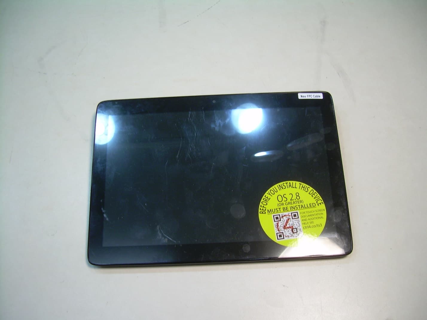
Jan 26, 2016Touchscreen Display for home automation system
Equipment Class
DTS - Digital Transmission System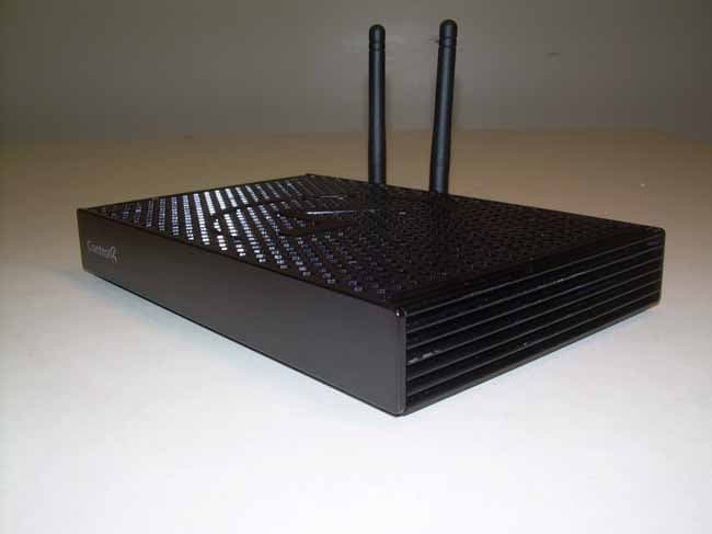
R33C4EA1
Jan 25, 2016Controller for home automation system
Equipment Class
DTS - Digital Transmission System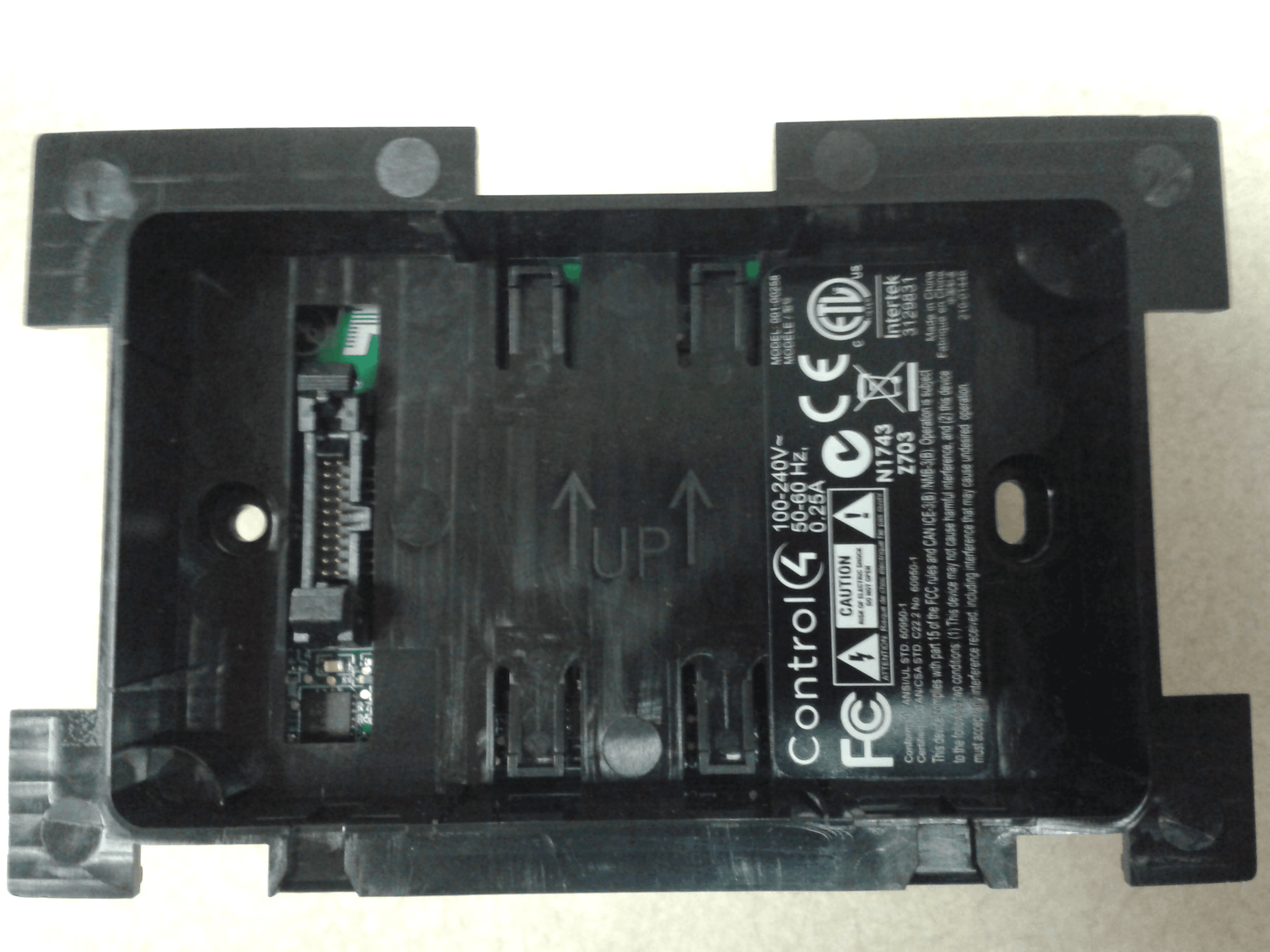
R33C4LGWM
Mar 24, 2015WIFI MODULE
Equipment Class
DTS - Digital Transmission System
R33C4SR260
Mar 18, 2015Remote control
Equipment Class
DTS - Digital Transmission System
R33C4THERM
Feb 09, 2015THERMOMETER
Equipment Class
DTS - Digital Transmission System