R33C4WMBC4-WMB-B
Snap One, LLC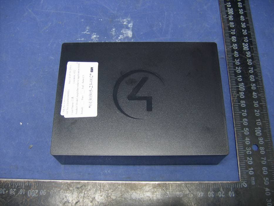
Click to zoom
Application Details
- Equipment Class
- DTS - Digital Transmission System
- Date of Grant
- Jun 04, 2013
- Application Purpose
- Original Equipment
- Date of Application
- Jun 03, 2013
- Equipment Note
- C4-WMB-B
- Frequency Range
- 2412.00000000 - 2462.00000000
- Company
- Snap One, LLC
- Country
- United States
Documents & Files
Document Text
Text extracted from the exhibit documents filed with the FCC. Open a document above to read the original.
Users Manual
™ Each Wireless Music Bridge can be given a unique name that appears on their smartphone/tablet and can be assigned to a specific room. It is also possible to assign the Wireless Music Bridge to an individual, so that the individual can listen to his/her music in their room of choice. This device uses Ethernet or WiFi connectivity to communicate with the Control4 system. Requirements • Control4 OS 2.5.0 or later. • Control4 controller fully installed and configured with a Control4 project. • Powered speakers or an available connection on an amplifier or stereo. Box Contents Carefully unpack the contents from the box, and make sure the following items are included: • Wireless Music Bridge • Power Supply • Warranty Card If any of these items is missing or damaged, please contact Control4 immediately. Specifications Dimensions (W x D x H) 6.29” (160 mm) x 4.72” (120 mm) x 1.57” (4 0 m m) Weight1.05 lbs. (.47 kg) Shipping Weight1.5 lbs. (.69 kg) Network10/100 BaseT Ethernet RJ-45 (preferred) or WiFi (802.11 b/g) Power SupplyDC - 5V @ 1.0A Connectivity10/100 BaseT Ethernet RJ-45 (preferred) WiFi (802.11b/g) Bluetooth v1.2 A2DP OutputsStereo Analog Digital SPDIF Supported Model C4-WMB-B Wireless Music Bridge Introduction The Control4® Wireless Music Bridge lets you play music, Internet radio, and podcasts from your smartphone devices through iOS (AirPlay®), Bluetooth®, Android or Windows (using DLNA). Simply attach the Wireless Music Bridge cables to a Control4 4-Zone Amplifier or Multi Channel Amplifier, add the device to a room in Composer, and you’re ready to go. This device supports OS 2.5.0 or later. The Wireless Music Bridge makes it easy to stream popular Internet music services, such as Pandora and Spotify, to any room in a home, using your smartphone. To enjoy separate streams of music, connect one Wireless Music Bridge for each zone on a 4-Zone Amplifier or Multi Channel Amplifier. The Wireless Music Bridge allows one (1) smartphone/tablet to be connected to the Control4 system at a time. It is possible for multiple phones to connect to the Wireless Music Bridge, but only one phone can output audio. More than one Wireless Music Bridge can be used in a Control4 system simultaneously, allowing individual users to connect their phone to their room of choice. Wireless Music Bridge Installation and Setup Guide 1 ™ Front View The following LED indicators appear, depending on whether the device is powered on and which type of device is connected to the Wireless Music Bridge. 1 Bluetooth—Displays the status of a Bluetooth connection. BLUE solid—Bluetooth is connected. 2 DLNA (Digital Living Network Alliance)— Displays the status of a DLNA connection. BLUE solid—DLNA is connected. 3 AirPlay—Displays the status of an AirPlay connection. BLUE flashing—The device is booting. BLUE solid—AirPlay is Ready/ Connected. 4 Power LED—Indicates that power is present. The Wireless Music Bridge turns on immediately after power is applied to it. BLUE solid—The power is on. NOTE: DLNA and AirPlay LEDs flash every second during a firmware update. Wireless Music Bridge Installation and Setup Guide Back View 1 5V DC (power jack)—Only connect the provided 5V power supply. 2 Reset/Restore (button)—Press one time to reset the Wireless Music Bridge but maintain its network settings. 3 ID (button)—Press one time to identify the Wireless Music Bridge in your Control4 system. 4 BT (button)—Manually disconnects Bluetooth and places the Wireless Music Bridge in pairing mode. 5 Analog Output (2 jacks)—Stereo analog output jacks for speakers and amplifiers. 6 Digital Output (1 jack)—Coaxial digital output jack for speakers and amplifiers. 7 Ethernet (port)—RJ-45 Ethernet jack for a 10/100 BaseT Ethernet connection. Network Options Connect the Wireless Music Bridge using one of these network types: CAUTION! If you are using Ethernet, connect the Ethernet cable before you power on the Wireless Music Bridge. The device will automatically go to WiFi mode if the power is plugged in before the Ethernet cable. • Standard Ethernet—For best results, this is the preferred option. Connect the Wireless Music Bridge to your network using a standard Ethernet cable. • WiFi—The Wireless Music Bridge is able to connect to your local wireless network and supports WEP, WPA, and WPA2 wireless networks. If you have an available local wireless network, no additional wiring is needed except for power. 1243522262276 2 1 2 4 3 IMPORTANT! Control4 recommends that you use an Ethernet connection rather than WiFi for the best communication with the Control4 system. Pre-Installation Considerations Before you decide where and how to install this device, review the information below. Location The Wireless Music Bridge is designed to work with AirPlay, DLNA and Bluetooth-enabled products. AirPlay and DLNA leverage the wired/wireless network in the home to bridge the smartphone/ tablets music into the Control4 system. If these modes are used, the Wireless Music Bridge can be mounted in a rack near the network switch and amplifier. If the Wireless Music Bridge is used for Bluetooth, then the Wireless Music Bridge must be installed in the room where the Wireless Music Bridge will be used. The Bluetooth radio in the Wireless Music Bridge is a Class 2 radio, which provides up to 10 meters line- of-sight. If obstructions, such as walls, electronics, wiring, or other wireless communication devices are near the Wireless Music Bridge, radio performance is degraded. For best results, make sure the Wireless Music Bridge is as close to the user as possible. Network Connectivity Although the Wireless Music Bridge can connect to the Control4 System via 802.11b/g, it is strongly encouraged to use the wired Ethernet connection for communicating with the Wireless Music Bridge. Bluetooth use and location of the Wireless Music Bridge must be considered when installing this device. If Bluetooth functionality is used by your customer, location must be decided early enough su…
Text truncated - open the document above for the full version.
Users Manual
Regulatory Compliance & Safety Information for Contol4 Model C4-WMB-B Electrical Safety Advisory Sécurité électrique consultatif Important Safety Information Informations de sécurité importantes Read the safety instructions before using this product. Lisez les consignes de sécurité avant d'utiliser ce produit. 1. Read these instructions. 1. Lisez ces instructions. 2. Keep these instructions. 2. Conservez ces instructions. 3. Heed all warnings. 3. Respectez tous les avertissements. 4. Follow all instructions. 4. Suivez toutes les instructions. 5. Do not use this apparatus near water. 5. Ne pas utiliser cet appareil près de l'eau. 6. Clean only with dry cloth. 6. Nettoyez-le uniquement avec un chiffon sec. 7. Do not block any ventilation openings. Install in accordance with the manufacturer’s instructions. 7. Ne pas bloquer les ouvertures de ventilation. Installer conformément aux instructions du fabricant. 8. Do not install near any heat sources such as radiators, heat registers, stoves, or other apparatus (including amplifiers) that produce heat. 8. Ne pas installer près de sources de chaleur telles que des radiateurs, registres de chaleur, poêles, ou autres appareils (incluant les amplificateurs) qui produisent de la chaleur. 9. Do not defeat the safety purpose of the polarized or grounding-type plug. A polarized plug has two blades with one wider than the other. A grounding type plug has two blades and a third grounding prong. The wide blade or the third prong is provided for your safety. If the provided plug does not fit into your outlet, consult an electrician for replacement of the obsolete outlet. 9. Ne pas contourner le dispositif de sécurité de la fiche polarisée ou de mise à la terre. Une fiche polarisée possède deux lames dont une plus large que l'autre. Une fiche de terre a deux lames et une troisième broche de terre. La lame large ou la troisième broche est fournie pour votre sécurité. Si la fiche fournie ne s'adapte pas à votre prise, consultez un électricien pour le remplacement de la prise obsolète. 10. Protect the power cord from being walked on or pinched particularly at plugs, convenience receptacles, and the point where they exit from the apparatus. 10. Protégez le cordon d'alimentation ne soit piétiné ou pincé, en particulier au niveau des fiches, des prises et au point où il sort de l'appareil. 11. Only use attachments/accessories specified by the manufacturer. 11. Utilisez uniquement des fixations / accessoires spécifiés par le fabricant. 12. Use only with the cart, stand, tripod, bracket, or table specified by the manufacturer, or sold with the apparatus. When a cart is used, use caution when moving the cart/apparatus combination to avoid injury from tip-over. 12. Utilisez uniquement avec le chariot, le socle, le trépied, le support ou la table spécifiés par le fabricant ou vendu avec l'appareil. Lorsque vous utilisez un chariot, soyez prudent lorsque vous déplacez l'ensemble chariot / appareil pour éviter des blessures dues au renversement. 13. Unplug this apparatus during lightning storms or when unused for long periods of time. This equipment uses AC power which can be subjected to electrical surges, typically lightning transients which are very destructive to customer terminal equipment connected to AC power sources. The warranty for this equipment does not cover damage caused by electrical surge or lightning transients. To reduce the risk of this equipment becoming damaged it is suggested that the customer consider installing a surge arrestor. 13. Débranchez cet appareil pendant les orages ou lorsqu'il n'est pas utilisé pendant de longues périodes de temps. Cet équipement utilise la puissance AC qui peuvent être soumis à des surtensions électriques, la foudre généralement transitoires qui sont très destructives envers les équipements terminaux connectés à des sources d'alimentation CA. La garantie de cet appareil ne couvre pas les dommages causés par les surtensions électriques ou transitoires de foudre. Pour réduire le risque de cet équipement devient endommagé, il est suggéré que le client envisager l'installation d'un limiteur de surtension. 14. Refer all servicing to qualified service personnel. Servicing is required when the apparatus has been damaged in any way, such as power-supply cord or plug is damaged, liquid has been spilled or objects have fallen into the apparatus, the apparatus has been exposed to rain or moisture, does not operate normally, or has been dropped. 14. Confiez toutes les réparations à un personnel qualifié. Une réparation est nécessaire lorsque l'appareil a été endommagé de quelque façon que ce soit le cordon d'alimentation ou la fiche est endommagé, du liquide a été renversé ou si des objets sont tombés dans l'appareil, l'appareil a été exposé à la pluie ou à l'humidité, ne fonctionne pas normalement , ou s'il est tombé. 15. Use the circuit breaker to disconnect the apparatus from the AC mains. The circuit breaker shall remain readily accessible. 15. Utiliser le disjoncteur pour déconnecter l'appareil de l'alimentation secteur. Le disjoncteur doit rester facilement accessible. 16. To completely disconnect unit power from the AC mains, turn off the circuit breaker. To reconnect power, turn on the circuit breaker following all safety instructions and guidelines. 16. Pour couper entièrement l'alimentation appareil de l'alimentation secteur, éteignez le disjoncteur. Pour rétablir le courant, mettez le disjoncteur après les consignes de sécurité et des lignes directrices. 17. This product relies on the buildings installation for short-circuit (overcurrent) protection. Ensure that the protective device is rated not greater than: 20A. 17. Ce produit repose sur l'installation des bâtiments pour les courts-circuits (surintensité) de protection. Assurez-vous que le dispositif de protection est assignée ne dépassant pas: 20A. 18. CAUTION: As with all batteries, there is a risk of explosion or personal injury if the battery is replaced by an …
Text truncated - open the document above for the full version.
Cover Letter(s)
DECLARATION OF CONFORMITY Per FCC Part 2 Section 2. 1077(a) The following equipment: Product Name : Wireless Music Bridge Trade Name : Control4 Model Number : C4-WMB-B It’s herewith confirmed to comply with the requirements of FCC Part 15 Rules. Operation is subject to the following two conditions: (1) This device may not cause harmful interference, and (2) This device must accept any interference received, including interference that may cause undesired operation. The result of electromagnetic emission has been evaluated by QuieTek EMC laboratory (NVLAP Lab. Code : 200533-0 ) and showed in the test report. ( Report No. : 136040R-ITUSP01V02 ) It is understood that each unit marketed is identical to the device as tested, and any changes to the device that could adversely affect the emission characteristics will require retest. The following importer / manufacturer is responsible for this declaration: Company Name Control4 Company Address 11734 S. Election Drive Suite 200, Draper, Utah, United States 84020 Telephone Facsimile : Person is responsible for marking this declaration: Name ( Full name ) Position / Title Date Legal Signature Sr. Regulatory Compliance Engineer Roger Midgley May 30, 2013
Cover Letter(s)
11734 South Election Road, Ste. 200 | Salt Lake City, Utah 84020 | www.control4.com | 801.523.3100 phone | 801.523.3199 fax Authority to Act as Agent Date: April 29, 2013 American Certification Body, Inc. 6731 Whittier Avenue Suite C110 McLean, VA 22101 To Whom It May Concern: Intertek Shanghai is authorized to act on our behalf, until otherwise notified, for applications to American Certification Body, Inc. (ACB). We certify that we are not subject to denial of federal benefits, that includes FCC benefits, pursuant to Section 5301 of the Anti-Drug Abuse Act of 1988, 21 U.S.C. 862. Further, no party, as defined in 47 CFR 1.2002 (b), to the application is subject to denial of federal benefits, that includes FCC benefits. Thank you, Agency Agreement Expiration Date: ____Dec 30, 2013____ By: Print Name: Roger Midgley Title: Sr. Regulatory Compliance Engineer On behalf of: Control4 Corporation (Company Name) Telephone: 801-523-3187
Cover Letter(s)
11734 South Election Road, Ste. 200 | Salt Lake City, Utah 84020 | www.control4.com | 801.523.3100 phone | 801.523.3199 fax April 29, 2013 CONFIDENTIALITY REQUEST LETTER Federal Communications Commission Authorization and Evaluation Division Confidentiality Request regarding application for certification of FCC ID: R33C4WMB Pursuant to Sections 0.457 and 0.459 of the Commission’s Rules, we hereby request the Commission to withhold the following attachments as confidential treatment of information from public disclosure indefinitely: Exhibit Type Schematics Block Diagrams Theory of Operation The above materials contain trade secrets and proprietary information not customarily released to the public. The public disclosure of these materials may be harmful to the applicant and provide unjustified benefits to its competitors. The applicant understands that pursuant to Section 0.457 of the Rules, disclosure of this application and all accompanying documentation will not be made before the date of the Grant for this application. Sincerely, Roger Midgley Sr. Regulatory Compliance Engineer
External Photos
FCC ID: R33C4WMB IC: 7848A-C4WMB Page 1 of 4 External Picture FCC ID: R33C4WMB IC: 7848A-C4WMB Page 2 of 4 FCC ID: R33C4WMB IC: 7848A-C4WMB Page 3 of 4 FCC ID: R33C4WMB IC: 7848A-C4WMB Page 4 of 4 AC/DC Adapter
ID Label/Location Info
SCALE 1:1DO NOT SCALESHEET 1 OF 2 REV SIZEPART # DESCRIPTION A210-01300 ANGLES: 1 2 PLACE DIMS: 0.02 3 PLACE DIMS: 0.005 TOLERANCES CHECKED APPROVED DATE DRAWN BY PLOT DATE DATEDATE UNLESS OTHERWISE SPECIFIED ALL DIMENSIONS ARE IN MILLIMETERS NOTES: UNLESS OTHERWISE SPECIFIED 1. MATERIAL PREMIUM COATED, THERMAL TRANSFER POLYESTER PAPER LABEL STOCK SEE PART NUMBER 211-00023 FOR MATERIAL SPECIFICATION AND APPROVED MANUFACTURES COLOR: BLACK 2. PRINTING USE ARTWORK SHOWN ON SHEET 2 OF ADOBE ILLUSTRATOR FILE PDF DOCUMENT IS FOR REFERENCE ONLY PRINT COLOR: PANTONE 7541 C (White) DOCUMENT SCHEDULE SHEET 1: ARTWORK SHEET 2: LABEL PLACEMENT 11764 S. Election Road, Suite #200 Draper, UT 84020 Phone: 801-523-3100 Fax: 801-523-3199 This document contains confidential information proprietary to Control4 and may not be copied in whole or in part by any means without the prior authorization of Control4. REVISION SPECIFICATION REV: NAME: RELEASE DATE: Wireless Music Bridge C C -- -- BETA RELEASE RELEASE TO PRODUCTION -- -- -- -- -- REVIEW GROUP CHECKED BY DATE -- -- -- -- -- -- -- -- -- -- ---- ENG. MANAGER REGULATORY MARKETING DOCUMENT CONTROL MECHANICAL ENG. ELECTRICAL ENG. 78.00 mm 30.00 mm HELGA KINKADE5/20/2013 N1743 Z703 4007877 Made in China 210-01300 MODEL: C4-WMB-B MODELE / 产品编号 FCC ID: R33C4WMB IC: 7848A-C4WMB This device complies with part 15 of the FCC rules and Industry Canada ICES-003. Operation is subject to the following two conditions: (1) This device may not cause harmful interference, and (2) this device must accept any interference received, including interference that may cause undesired operation. 5V , 1A, 5W Conforms to ANSI/UL STD. 60950-1 Certified to CAN/CSA STD. C22.2 No. 60950-1 210-01300 SCALE N.T.S.DO NOT SCALESHEET 2 OF 2 REV SIZEPART # DESCRIPTION A CHECKED APPROVED DATE DRAWN BY PLOT DATE DATEDATE UNLESS OTHERWISE SPECIFIED ALL DIMENSIONS ARE IN MILLIMETERS Wireless Music Bridge C -- -- -- -- -- HELGA KINKADE5/20/2013 N1743 Z703 4007877 Made in China 210-01300 MODEL: C4-WMB-B MODELE / 产品编号 FCC ID: R33C4WMB IC: 7848A-C4WMB This device complies with part 15 of the FCC rules and Industry Canada ICES-003. Operation is subject to the following two conditions: (1) This device may not cause harmful interference, and (2) this device must accept any interference received, including interference that may cause undesired operation. 5V , 1A, 5W Conforms to ANSI/UL STD. 60950-1 Certified to CAN/CSA STD. C22.2 No. 60950-1
Internal Photos
FCC ID: R33C4WMB IC: 7848A-C4WMB Page 1 of 6 Internal Picture FCC ID: R33C4WMB IC: 7848A-C4WMB Page 2 of 6 FCC ID: R33C4WMB IC: 7848A-C4WMB Page 3 of 6 Wi-Fi module FCC ID: R33C4WMB IC: 7848A-C4WMB Page 4 of 6 FCC ID: R33C4WMB IC: 7848A-C4WMB Page 5 of 6 Bluetooth module FCC ID: R33C4WMB IC: 7848A-C4WMB Page 6 of 6 Wi-Fi & Bluetooth Antenna
RF Exposure Info
FCC ID: R33C4WMB IC: 7848A-C4WMB Page 1 of 2 Statement of compliance to Maximum Permissible Exposure (MPE) Applicant : Control4 11734 S. Election Drive Suite 200, Draper, Utah, United States 84020 Manufacturer : Hansong (Nanjing) Technology Ltd. 8 Kangping Road, jiangning Econ. And Tech. Development Zone, Nanjing, 211106, China Equipment : Wireless Music Bridge Type/Model : C4-WMB-B According to §2.1091, §2.1093 and §1.1307(b), systems operating under the provisions of this section shall be operated in a manner that ensures that the public is not exposed to radio frequency energy level in excess of the Commission’s guidelines. The S = PG / (4πR²) Where S = power density in mW/cm² P = transmit power in mW G = numeric gain of transmit antenna R = distance (cm) R is chosen to be 20cm, the gain of antenna G = 3.00dBi = 1.995 As we can see from the test reports 130300367SHA-001: The maximum output power for Wi-Fi = 24.02dBm= 252.348mW The MPE of Wi-Fi = PG / (4πR²) = 252.348 * 1.995 / (4 * 3.14 * 20 * 20) = 0.10 As we can see from the test reports 130300367SHA-002: The maximum output power for Bluetooth = 3.23dBm = 2.104mW The MPE of Bluetooth = PG / (4πR²) = 2.104 * 1.995 / (4 * 3.14 * 20 * 20) = 0.00084mW/cm² For the device can support simultaneous transmission, according to 447498 D01 General RF Exposure Guidance v05r01, The sum of the MPE ratios = 0.10 / 1.0 + 0.00084 / 1.0 = 0.10 This level is below the simultaneous transmission MPE test exclusion requirements (≤1.0). Date of issue: May 13, 2013 Prepared by: Reviewed by: Wakeyou Wang (Project Engineer) Daniel Zhao (Reviewer) FCC ID: R33C4WMB IC: 7848A-C4WMB Page 2 of 2 Appendix I Definition below must be outlined in the User Manual: To satisfy FCC RF exposure requirements, a separation distance of 20 cm or more should be maintained between the antenna of this device and persons during device operation. To ensure compliance, operations at closer than this distance is not recommended.
Test Report
FCC ID: R33C4WMB IC: 7848A-C4WMB Page 1 of 44 EMC TEST REPORT for Intentional Radiator (Wi-Fi Function) No. 130300367SHA-001 Applicant : Control4 11734 S. Election Drive Suite 200, Draper, Utah, United States 84020 Manufacturer : Hansong (Nanjing) Technology Ltd. 8 Kangping Road, jiangning Econ. And Tech. Development Zone, Nanjing, 211106, China Equipment : Wireless Music Bridge Type/Model : C4-WMB-B SUMMARY The equipment complies with the requirements according to the following standard(s): 47CFR Part 15 (2012): Radio Frequency Devices ANSI C63.4 (2003): American National Standard for Methods of Measurement of Radio-Noise Emissions from Low-Voltage Electrical and Electronic Equipment in the Range of 9 kHz to 40 GHz RSS-210 Issue 8 (December 2010): Low-power Licence-exempt Radiocommunication Devices (All Frequency Bands): Category I Equipment RSS-Gen Issue 3 (December 2010): General Requirements and Information for the Certification of Radiocommunication Equipment Date of issue: May 13, 2013 Prepared by: Reviewed by: Wakeyou Wang (Project Engineer) Daniel Zhao (Reviewer) FCC ID: R33C4WMB IC: 7848A-C4WMB Page 2 of 44 Description of Test Facility Name: Intertek Testing Services Limited Shanghai Address: Building No.86, 1198 Qinzhou Road(North), Shanghai 200233, P.R. China FCC Registration Number: 236597 IC Assigned Code: 2042B-1 Name of contact: Steve Li Tel: +86 21 64956565 ext. 214 Fax: +86 21 54262335 ext. 214 FCC ID: R33C4WMB IC: 7848A-C4WMB Page 3 of 44 Content SUMMARY .......................................................................................................................................................... 1 1. GENERAL INFORMATION ............................................................................................................................ 4 1.1 Applicant Information ..................................................................................................... 4 1.2 Identification of the EUT ................................................................................................ 4 1.3 Technical specification ................................................................................................... 5 1.4 Mode of operation during the test / Test peripherals used .............................................. 5 2. TEST SPECIFICATION .................................................................................................................................. 6 2.1 Instrument list ................................................................................................................. 6 2.2 Test Standard .................................................................................................................. 6 2.3 Test Summary ................................................................................................................. 7 3. MINIMUM 6DB BANDWIDTH ....................................................................................................................... 9 3.1 Limit ................................................................................................................................ 9 3.2 Test Configuration .......................................................................................................... 9 3.3 Test Procedure and test setup .......................................................................................... 9 3.4 Test Protocol ................................................................................................................. 10 4. MAXIMUM PEAK OUTPUT POWER ............................................................................................................. 14 4.1 Test limit ....................................................................................................................... 14 4.2 Test Configuration ........................................................................................................ 14 4.3 Test procedure and test setup ........................................................................................ 14 4.4 Test protocol ................................................................................................................. 15 5. POWER SPECTRUM DENSITY ..................................................................................................................... 19 5.1 Test limit ....................................................................................................................... 19 5.2 Test Configuration ........................................................................................................ 19 5.3 Test procedure and test setup ........................................................................................ 19 5.4 Test Protocol ................................................................................................................. 20 6. RADIATED EMISSION ................................................................................................................................. 24 6.1 Test limit ....................................................................................................................... 24 6.2 Test Configuration ........................................................................................................ 24 6.3 Test procedure and test setup ........................................................................................ 25 6.4 Test protocol ................................................................................................................. 26 7. EMISSION OUTSIDE THE FREQUENCY BAND ............................................................................................. 32 7.1 Limit .............................................................................................................................. 32 7.2 Test Configuration ........................................................................................................ 32 7.3 Test proced…
Text truncated - open the document above for the full version.
Test Setup Photos
FCC ID: R33C4WMB IC: 7848A-C4WMB Page 1 of 5 Test Setup FCC ID: R33C4WMB IC: 7848A-C4WMB Page 2 of 5 1. Radiated Emission Bluetooth test, 30MHz-1000MHz FCC ID: R33C4WMB IC: 7848A-C4WMB Page 3 of 5 Bluetooth test, higher than 1GHz FCC ID: R33C4WMB IC: 7848A-C4WMB Page 4 of 5 Wi-Fi test, 30MHz-1000MHz FCC ID: R33C4WMB IC: 7848A-C4WMB Page 5 of 5 Wi-Fi test, higher than 1GHz
Contact Information
Applicant
Roger J Midgley(Principle Compliance Engineer)
Technical Contact
Intertek Testing Services Limited ShanghaiWakeyou Wang
[email protected]86 21 61278448
Building No.86, 1198 Qinzhou Road(North) · Shanghai · China
Test Firm
Intertek Testing Services Limited ShanghaiJonny Jing
Technical Specifications
| # | Rule Parts | Frequency Range | Power Output |
|---|---|---|---|
| 1 | 15C | 2.41 GHz - 2.46 GHz | 252.00 mW |
Other Applications from Snap One, LLC
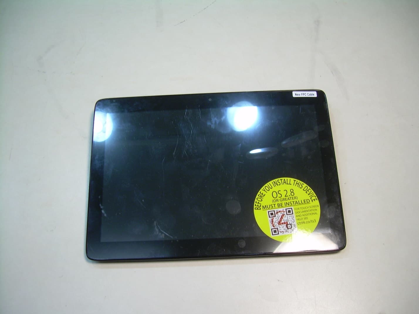
R33C4TT10
Jan 26, 2016Touchscreen Display for home automation system
Equipment Class
DTS - Digital Transmission System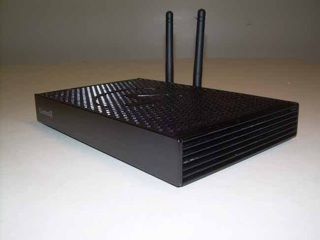
R33C4EA1
Jan 25, 2016Controller for home automation system
Equipment Class
DTS - Digital Transmission System
R33C4LGWM
Mar 24, 2015WIFI MODULE
Equipment Class
DTS - Digital Transmission System
R33C4SR260
Mar 18, 2015Remote control
Equipment Class
DTS - Digital Transmission System
R33C4THERM
Feb 09, 2015THERMOMETER
Equipment Class
DTS - Digital Transmission System