R33C4HC5001Home Controller HC-500
Snap One, LLC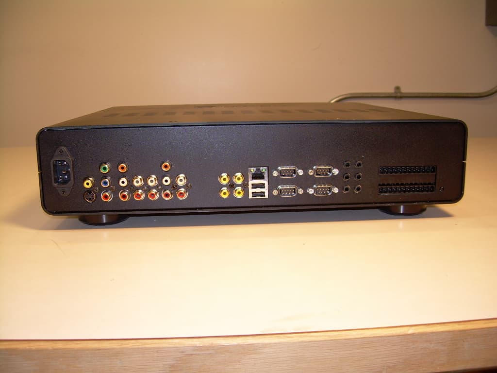
Click to zoom
Application Details
- Equipment Class
- DTS - Digital Transmission System
- Date of Grant
- Oct 28, 2007
- Application Purpose
- Original Equipment
- Date of Application
- Oct 28, 2007
- Equipment Note
- Home Controller HC-500
- Frequency Range
- 2405.00000000 - 2475.50000000
- Company
- Snap One, LLC
- Country
- United States
Documents & Files
Document Text
Text extracted from the exhibit documents filed with the FCC. Open a document above to read the original.
Users Manual
Home Controller HC-500 Installation Guide Supported Model C4-HC500-E-B Home Controller HC-500 Graphical Symbols in this Guide The following symbols and their descriptions draw your attention to important safe practices and additional information that can help you avoid death, injury, or loss of material or time. WARNING! This indicates a potentially hazardous situation that, if not avoided, may result in death or serious injury. DO NOT IGNORE A WARNING! IMPORTANT! This indicates information that will help you avoid damage to your equipment, loss of materials, or loss of time. PAY ATTENTION TO THESE IMPORTANT STATEMENTS! NOTE: This indicates information related to the current topic. Important Safety Instructions 1. Read these instructions. 2. Keep these instructions. 3. Heed all warnings. 4. Follow all instructions. 5. Do not use this apparatus near water. 6. Clean only with dry cloth. 7. Install in accordance with the manufacturer’s instructions. 8. Do not install near any heat sources such as radiators, heat registers, stoves, or other apparatus (including amplifiers) that produce heat. 9. Do not defeat the safety purpose of the polarized or grounding-type plug. A polarized plug has two blades with one wider than the other. A grounding type plug has two blades and a third grounding prong. The wide blade or the third prong are provided for your safety. If the provided plug does not fit into your outlet, consult an electrician for replacement of the obsolete outlet. 10.Protect the power cord from being walked on or pinched particularly at plugs, convenience receptacles, and the point where they exit from the apparatus. 11.Only use attachments/accessories specified by the manufacturer. 12.Unplug this apparatus during lighting storms or when unused for long peri- ods of time. 13.Refer all servicing to qualified service personnel. Servicing is required when the apparatus has been damaged in any way, such as power-supply cord or plug is damaged, liquid has been spilled or objects have fallen into the apparatus, the apparatus has been exposed to rain or moisture, does not operate normally, or has been dropped. 14.This apparatus has no AC mains power switch. The power cable is the AC mains disconnect device. WARNING! To reduce the risk of electrical shock, do not expose this apparatus to rain or moisture. WARNING! This CLASS I apparatus must be connected to an AC mains socket outlet that has a protective earthing connection (i.e., third- prong ground conductor). DO NOT DEFEAT THE PROTECTIVE EARTHING CONNECTION! Introduction to Home Controller HC-500 The Control4 Home Controller HC-500 provides options for controlling lights, home theaters, distributed audio systems, and other devices controlled using various protocols, such as Infra Red (IR), Serial, Contact, and Relay. It provides extensive media management services for audio sources, such as CDs and DVDs stored in connected devices. It also allows you to use an external storage device with USB support for media storage. It also includes multi-zone audio capabilities, sending music to rooms throughout the home. Once the controller and other system components are installed and configured (using Control4 Composer software or another Control4 setup program), your users can control the system using one of the two user interfaces included with this controller: On-screen Navigator or System Remote Control or any other Control4 user interface device (available separately). Control4 Supported Devices Control4 devices that can be controlled by this controller include: For a more information see “Products” at http://www.control4.com . Specifications Prior to installing this product, ensure that: Ethernet network wiring is in place. The Home Controller HC-500 specifications include: What’s in the Box The following are included in your Home Controller box: • Home Controller HC-500 • Pluggable terminal block connector (4) • System Remote Control with LCD Navigator display and 4 AAA batteries • IEC 320 power cord • IR emitters (6) •Home Controller HC-500 Installation Guide (this document) •Control4 System User Guide • Control4 System Remote Control User Guide Accessories Available for Purchase • USB WiFi Adapter for HC-500 (C4-NWA-11G-USB) Warranty Limited 2-year Warranty. Refer to http://www.control4.com/warranty. Additional Resources The following resources are available to provide you with additional support. • Your authorized Control4 reseller • Control4 Web Site: http://www.control4.com • Composer online help Front View 1.WiFi LED—This LED blinks first red, then orange, and finally blue during the boot process. Once the operating system is running, the WiFi driver changes the LED color depending on the signal strength of its connection to its associated access point. Colors and signal strength are as follows: orange = Fair to Good, blue = Excellent, and no light = No connection. 2.Data LED—This blue LED indicates streaming audio is received. 3.Link LED—Blue LED light indicates Home Controller has been identified in a Control4 Composer project. 4.Power LED—Blue LED light indicates AC power is present. It turns on immediately after the power is applied to the device. 5.IR Window / IR Blaster—For capturing third-party IR codes from hand-held devices (such as remote controls) or blasting IR codes. Back View 1.Power plug port—AC power receptacle for an IEC 320 power cord. 2.Video Out—Composite RCA, S-VIDEO mini-DIN, and Component RCA jacks. 3. Digital Coax Audio Out 4.Audio Out (3 Left-Right pairs)—RCA jacks for stereo channel line output (line level) for amplifiers or audio switches. 5. Digital Coax Audio In 6.Audio In (2 Left-Right pairs)—RCA jacks for stereo channel input (line level) for two stereo analog sources. 7.Video Sense In-Out (2 pairs)—Composite In-Out RCA jack pairs for moni- toring the On/Off status of up to two video sources. 8.Ethernet—RJ-45 jack for a 10/100 BaseT Ethernet connection. 9.USB (2 ports)—For external storage device with USB su…
Text truncated - open the document above for the full version.
Cover Letter(s)
11734 South Election Drive Suite 200 Draper, Utah 84020 (801) 523-3100 To: Federal Communications Commission Date: 1/22/07 445 12 th Street, SW Washington, DC 20554 Re: Non disclosure Request for FCC ID: R33C4HC5001 We are requesting that the following documents be held and treated as confidential and proprietary information. These materials contain technical trade secret information and should be guarded from competitors as stated under the Code of Federal Regulations Title 47 Section 0.459 (3), (4) and (5). 1) Schematic 2) Block Diagrams 3) Operational Description Grant W. Dearden Hardware Engineer Control4 Technologies
External Photos
Front View of the EUT Back View of the EUT
ID Label/Location Info
Control4 CONFIDENTIAL R33C4HC5001 Label and Placement Documentation 1. Wording: See paragraph below This device complies with Part 15 of the FCC Rules. Operation is subject to the following two conditions: (1) this device may not cause harmful interference, and (2) this device must accept any interference received, including interference that may cause undesired operation. 2. Label – FCC Compliance: See actual full size label below Placement: Place label on the bottom of the HC-500 directly underneath the location of the video connectors. 3. Label – FCC ID: See actual full size label below Placement: Place label on the HC-500 box in the area designated. This device complies with Part 15 of the FCC Rules. Operation is subject to the following two conditions: (1) this device may not cause harmful interference, and (2) this device must accept any interference received, including interference that may cause undesired operation.
Internal Photos
Internal View Front of the EUT Component Side of the Main PCB Trace Side of the Main PCB Component Side of the Front Panel/Transceiver PCB Trace Side of the Front Panel/Transceiver PCB
RF Exposure Info
1 MPE Calculations R33C4HC5001 2 1.0 SCOPE_________________________________________________________3 2.0 REVISION LEVEL_______________________________________________3 3.0 REFERENCE DOCUMENTS______________________________________3 4.0 CALCULATIONS________________________________________________3 5.0 CONCLUSION__________________________________________________4 3 1.0 SCOPE: This Report Demonstrates Evaluation and Compliance for Human Exposure to Electromagnetic Fields as Outlined by the Federal Communications Commission Office of Engineering and Technology Bulletin 65. 2.0 REVISION LEVEL: DATE COMMENTS REVISION 1/22/2007 Created. 1.0 10/25/2007 Change the FCC number 2.0 3.0 REFERANCE DOCUMENTS: (A) Limits for Maximum Permissible Exposure (MPE). Code of Federal Regulations Title 47, Volume 1, Sections 1.1310 (B) Limits for Maximum Permissible Exposure (MPE). Code of Federal Regulations Title 47, Volume 1, Sections 2.1093 (C) Evaluating Compliance with FCC Guidelines for Human Exposure to Radiofrequency Electromagnetic Fields. OET Bulletin 67 Edition 97-01. 4.0 CALCULATIONS: The following worst case emissions are based on a PPt (Peak Power Total) measurement of 0.0 dBm into the antenna. And the worst case antenna gain on axis is found to be 1.0 dBi. Total power into antenna: A) Pt = 0.0 dBm = 10^(0.0 dBm/10) = 1.0 mW Total effective isotropic radiated power at the Transmitter: B) EIRP = 1.0 dBm + 1.0dBi = 2.0 dBm 2.0 dBm = 1.58 mW Power density at a distance of 20 centimeters is: 4 C) 2 Rπ4 EIRP =S = 0.31 μW/cm 2 Where S = Power density (mW/cm^2), EIRP = Equivalent isotropic radiated power (mW), R = Distance to the center of radiation of the antenna (cm) 5.0 CONCLUSION: Based on the FCC Limits for Maximum Permissible Exposure (MPE) given in Table 1 of reference document (A) as 1 mW/cm 2 this device falls under the required limits.
Test Report
COMMUNICATION CERTIFICATION LABORATORY 1940 West Alexander Street Salt Lake City, UT 84119 801-972-6146 Test Report Certification Test Of: C4-HC500-E-B FCC ID: R33C4HC5001 Test Specification: FCC PART 15, Subpart C Test Report Serial No:1151 Applicant: Control4 11734 S. Election Road, Suite 200 Draper, UT 84020 Date of Test: October 18, 2007 Issue Date: October 23, 2007 Accredited Testing Laboratory By: NVLAP Lab Code 100272-0 COMMUNICATION CERTIFICATION LABORATORY TEST REPORT: 1151 FCC ID#: R33C4HC5001 Page 2 of 47 CERTIFICATION OF ENGINEERING REPORT This report has been prepared by Communication Certification Laboratory to document compliance of the device described below with the requirements of Federal Communications Commission (FCC) Part 15, Subpart C. This report may be reproduced in full, partial reproduction may only be made with the written consent of the laboratory. The results in this report apply only to the sample tested. - Applicant: Control4 - Manufacturer: Control4 - Brand Name: Control4 - Model Number: C4-HC500-E-B - FCC ID Number: R33C4HC5001 On this 23 rd day of October 2007, I, individually, and for Communication Certification Laboratory, certify that the statements made in this engineering report are true, complete, and correct to the best of my knowledge, and are made in good faith. Although NVLAP has recognized that the Communication Certification Laboratory EMC testing facilities are in good standing, this report must not be used to claim product certification, approval, or endorsement by NVLAP, NIST, or any agency of the federal government. COMMUNICATION CERTIFICATION LABORATORY Tested by: Norman P. Hansen EMC Technician COMMUNICATION CERTIFICATION LABORATORY TEST REPORT: 1151 FCC ID#: R33C4HC5001 Page 3 of 47 TABLE OF CONTENTS PAGE SECTION 1.0 CLIENT INFORMATION.................................4 SECTION 2.0 EQUIPMENT UNDER TEST (EUT) ..........................5 SECTION 3.0 TEST SPECIFICATION, METHODS & PROCEDURES ...........9 SECTION 4.0 OPERATION OF EUT DURING TESTING ...................16 SECTION 5.0 SUMMARY OF TEST RESULTS...........................17 SECTION 6.0 MEASUREMENTS, EXAMINATIONS AND DERIVED RESULTS.....18 APPENDIX 1 TEST PROCEDURES AND TEST EQUIPMENT ..................31 APPENDIX 2 PHOTOGRAPHS.........................................37 COMMUNICATION CERTIFICATION LABORATORY TEST REPORT: 1151 FCC ID#: R33C4HC5001 Page 4 of 47 SECTION 1.0 CLIENT INFORMATION 1.1 Applicant: Company Name: Control4 11734 S. Election Road, Suite 200 Draper, UT 84020 Contact Name: Grant Dearden Title: Senior Engineer 1.2 Manufacturer: Company Name: Control4 11734 S. Election Road, Suite 200 Draper, UT 84020 Contact Name: Grant Dearden Title: Senior Engineer COMMUNICATION CERTIFICATION LABORATORY TEST REPORT: 1151 FCC ID#: R33C4HC5001 Page 5 of 47 SECTION 2.0 EQUIPMENT UNDER TEST (EUT) 2.1 Identification of EUT: Brand Name: Control4 Model Number: C4-HC500-E-B Serial Number: None Options Fitted: N/A Country of Manufacture: China 2.2 Description of EUT: The C4-HC500-E-B is a controller for a home automation system. Typical applications include automating home theater, multi-room music, lighting, temperature, and security. The C4- HC500-E-B has a main PCB, a front panel/transceiver PCB, a Western Digital WD3200YS hard drive, and a Mean Well TF-449 power supply. The C4-HC500-E-B uses an 802-15.4 Zigbee transceiver to interface a home network. Other interfaces include IR, Serial, Ethernet, USB, Audio, video, video sense, contacts, and relays. The 802.15.4 transceiver uses 15 channels in the 2400 to 2483.5 MHz band. The individual channels are shown in the following plots. dBm 2 -8 -18 -28 -38 -48 -58 -68 -78 -88 -98 Control4 Trace A Start: 2.402500 GHzStop: 2.427500 GHz Res BW: 100 kHzVid BW: 300 kHzSweep: 20 ms 10/18/2007 2:06:10 PMHP8566B Trace A Lower channels plot 1 1 2.405000 GHz -8.1000 dBm 2 2 2.410075 GHz -7.2000 dBm 3 3 2.415050 GHz -7.5000 dBm 4 4 2.420100 GHz -7.1000 dBm 5 5 2.425150 GHz -8.0000 dBm COMMUNICATION CERTIFICATION LABORATORY TEST REPORT: 1151 FCC ID#: R33C4HC5001 Page 6 of 47 dBm 2 -8 -18 -28 -38 -48 -58 -68 -78 -88 -98 Control4 Trace A Start: 2.427500 GHzStop: 2.452500 GHz Res BW: 100 kHzVid BW: 300 kHzSweep: 20 ms 10/18/2007 2:09:42 PMHP8566B Trace A Middle 5 channel plot 1 1 2.430000 GHz -7.8000 dBm 2 2 2.435100 GHz -7.8000 dBm 3 3 2.440175 GHz -6.6000 dBm 4 4 2.445250 GHz -7.4000 dBm 5 5 2.450350 GHz -8.0000 dBm dBm 2 -8 -18 -28 -38 -48 -58 -68 -78 -88 -98 Control4 Trace A Start: 2.452500 GHzStop: 2.477500 GHz Res BW: 100 kHzVid BW: 300 kHzSweep: 20 ms 10/18/2007 2:12:01 PMHP8566B Trace A Upper 5 channel plot 1 1 2.455000 GHz -7.4000 dBm 2 2 2.460175 GHz -8.6000 dBm 3 3 2.465375 GHz -7.3000 dBm 4 4 2.470425 GHz -7.6000 dBm 5 5 2.475500 GHz -9.5000 dBm This report covers the transceiver circuitry of this device. The other circuitry, subject to FCC 15 Subpart B, is to be tested and covered in a separate report. COMMUNICATION CERTIFICATION LABORATORY TEST REPORT: 1151 FCC ID#: R33C4HC5001 Page 7 of 47 2.3 EUT and Support Equipment: The FCC ID numbers for all the EUT and support equipment used during the test (including inserted cards) are listed below: Brand Name Model Number Serial Number FCC ID Number Description Name of Interface Ports / Interface Cables BN: Control4 MN: C4-HC500-E-B (Note 1) R33C4HC5001 System Controller See Section 2.4 BN: TRENDnet MN: TEG-S50TXE DoC 5 port Ethernet Hub Ethernet/Cat5 cable (Note 2) Note: (1) EUT (2) Interface port connected to EUT (See Section 2.4) The support equipment listed above was not modified in order to achieve compliance with this standard. 2.4 Interface Ports on EUT: Name of Ports No. of Ports Fitted to EUT Cable Descriptions/Length Video Out - Composite 1 RCA cable/1.5 meter Video Out – S-video 1 S-video cable/1.5 meter Component Video Out (Y, Pb, Pr) 1 RCA cable/1.5 meters Analog Audio Out Left and Right 3 RCA cable/1.5 meter Digital Audio Out 1 RCA cable/1.5 meter Analog Audio In Left and Right 2 RCA ca…
Text truncated - open the document above for the full version.
Test Setup Photos
Front View Radiated Disturbance Worst Case Configuration Back View Radiated Disturbance Worst Case Configuration Front View Conducted Disturbance Worst Case Configuration Back View Conducted Disturbance Worst Case Configuration
Contact Information
Applicant
Roger J Midgley(Principle Compliance Engineer)
Test Firm
Nemko-CCL, IncThomas Jackson
Technical Specifications
| # | Rule Parts | Frequency Range | Power Output |
|---|---|---|---|
| 1 | 15C | 2.40 GHz - 2.48 GHz | 390.00 µW |
Other Applications from Snap One, LLC
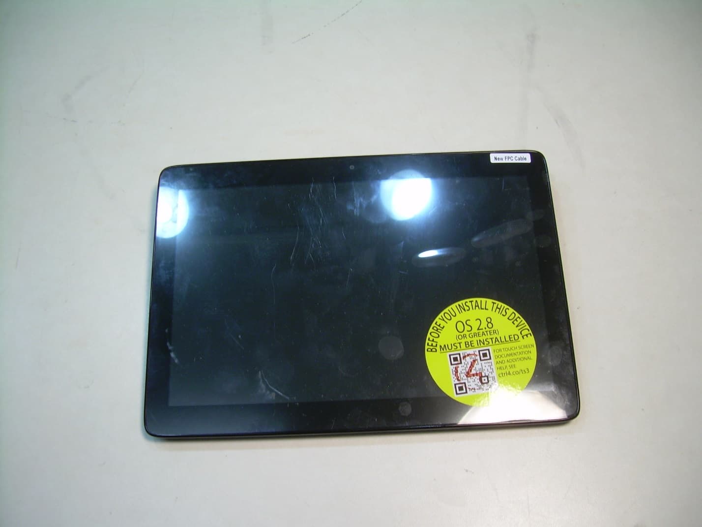
R33C4TT10
Jan 26, 2016Touchscreen Display for home automation system
Equipment Class
DTS - Digital Transmission System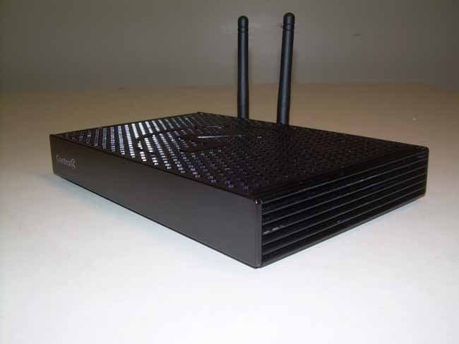
R33C4EA1
Jan 25, 2016Controller for home automation system
Equipment Class
DTS - Digital Transmission System
R33C4LGWM
Mar 24, 2015WIFI MODULE
Equipment Class
DTS - Digital Transmission System
R33C4SR260
Mar 18, 2015Remote control
Equipment Class
DTS - Digital Transmission System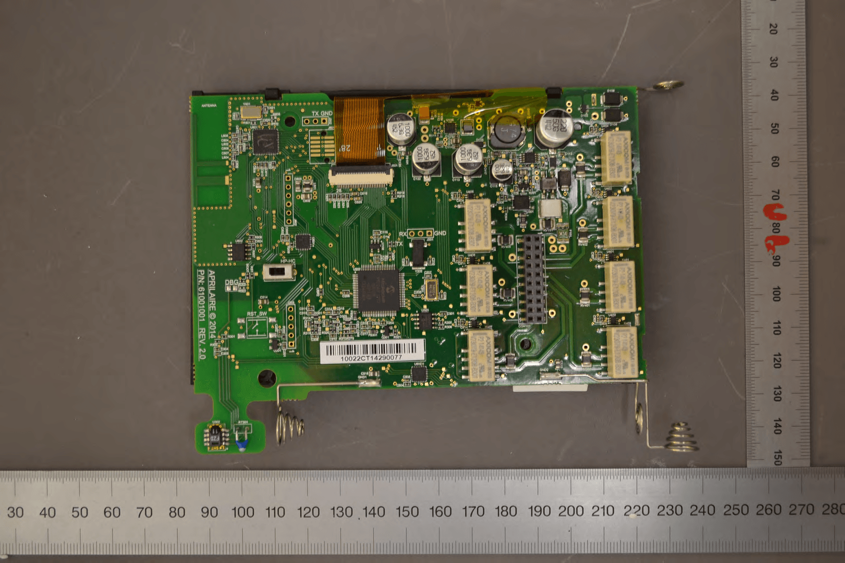
R33C4THERM
Feb 09, 2015THERMOMETER
Equipment Class
DTS - Digital Transmission System