R33C4KCCONFIGURABLE KEYPAD WITH ZIGBEE
Snap One, LLC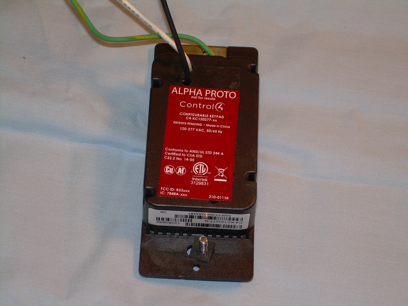
Click to zoom
Application Details
- Equipment Class
- DTS - Digital Transmission System
- Date of Grant
- Feb 12, 2013
- Application Purpose
- Original Equipment
- Date of Application
- Feb 12, 2013
- Equipment Note
- CONFIGURABLE KEYPAD WITH ZIGBEE
- Frequency Range
- 2405.00000000 - 2475.00000000
- Company
- Snap One, LLC
- Country
- United States
Documents & Files
Document Text
Text extracted from the exhibit documents filed with the FCC. Open a document above to read the original.
Users Manual
™ WARNING! Improper use or installation can cause SERIOUS INJURY, DEATH or LOSS/DAMAGE OF PROPERTY. WARNING! If you are unsure about any part of these instructions, consult a qualified electrician. WARNING! To reduce the risk of SERIOUS INJURY or DEATH, turn OFF local electrical power before installing this product, and before installing, removing, or replacing keycaps. WARNING! Use this device only with copper or copper-clad wire. Do not use aluminum wiring. This product has not been approved for use with aluminum wiring. WARNING! This device must be protected by a circuit breaker (20A max). IMPORTANT! Using this product in a manner other than outlined in this document voids your warranty. Further, Control4 is NOT liable for any damage incurred with the misuse of this product. See “Troubleshooting.” IMPORTANT! Do NOT use a power screwdriver to install this device. If you do, you may overtighten the screws and strip them. Also, overtightening the screws may interfere with proper button operation. IMPORTANT! This is an electronic device with intricate components. Handle and install with care! Installation Instructions 1 Ensure that the location and intended use meet the following criteria: • When replacing a traditional 3-way switch, refer to the “Two-Location” sample wiring configurations provided in the appropriate load control device installation guide. • Install in accordance with all national and local electrical codes. • The range and performance of the wireless control system is highly dependent on the following: (1) distance between devices; (2) layout of the home; (3) walls separating devices; and (4) electrical equipment located near devices. WARNING! To reduce the risk of SERIOUS INJURY or DEATH, turn OFF local electrical power before installing this product. 2 Turn off the local electrical power by either switching off the circuit breaker or removing the fuse from the fuse box. To ensure the wires do NOT have power running to them, use an inductive voltage detector. WARNING! As with any electrical device, improper use or installation can cause SERIOUS INJURY or DEATH. It is important that you understand the particular wiring configuration of your installation before proceeding. NOTE: The wallbox wiring shown in this document is an example. Your wire colors and functions may differ. If you are not sure which wires are the Hot, Neutral, and Ground wires, have a trained electrician do the installation. 3 Prepare each wire. Wire insulation should be stripped back 5/8 of an inch from the wire end (see Figure 1). Supported Model • C4-KC120277 Wireless Configurable Keypad Introduction The Control4® Wireless Configurable Keypad is intended for use in a Control4 system. It installs in a standard wall box using typical wiring standards and communicates to the Control4 system using a wireless connection. Box Contents • Wireless Configurable Keypad • Button Kit • Wire Nuts • Warranty Card • Wireless Configurable Keypad Installation Guide (this document) Specifications The specifications are described below. Model NumberC4-KC120277-xx Power Requirements110-277 VAC +/-10% 50/60 Hz This device requires a neutral AC connection. Power Consumption1 W Environmental Operational Temperature32 ̊ F - 104 ̊ F (0 ̊ C - 40 ̊ C) All load ratings are based on an ambient temperature of 25 ̊ C. Humidity5% to 95% non-condensing Storage-4 ̊ F - 158 ̊ F (-20 ̊ C - 70 ̊ C) Miscellaneous Control CommunicationsZigBee, IEEE 802.15.4, 2.4 GHz, 15-channel spread spectrum radio Wallbox Volume4.75 cubic inches Warnings and Considerations WARNING! This device must be installed by a licensed electrician in accordance with all national and local electrical codes. Configurable Keypad Installation Guide Figure 1. Strip Wire Insulation WARNING! Ground the keypad in accordance with the National Electric Code (NEC) requirements. DO NOT rely solely upon the yoke plate’s contact with a metal wallbox for adequate grounding. Use the keypad’s ground wire to make a secure connection to the safety ground of the electrical system. IMPORTANT! Not grounding this product according to the preceding may result in an installation less immune to damage caused by electrical disturbances, such as ESD or lightning, and may void the warranty. 4 Identify and connect the keypad wires to the wallbox wires using the wire nuts. NOTE: Wallbox wires can differ depending upon how the box was wired by your electrician. 5 To wire the keypad, connect and cap the wires with a wire nut as indicated in the following figure and table. Figure 2. Keypad Wiring Configurable Keypad WiresWires in Wall Box White (neutral)White (neutral) Green (ground)Green (ground) Black (hot)Black (hot) 6 Fit the wires back into the wallbox. Bend the wires in a zigzag pattern so that they easily fold into the wallbox (Figure 3). Figure 3. Bend the Wires 7 If you are using a Control4 push-on (screwless) wall plate: a. Align the keypad to the wallbox (the model # label should be at the bottom) and fasten it with screws. Tighten the screws until the back side of the yoke plate is even with the wall surface, but no further. Overtightening can warp the configurable keypad and cause mechanical malfunction. TIP: In multi-gang installations, leave the screws that attach the keypad to the wallbox slightly loose until the faceplate’s sub-plate is attached to all the devices. This allows all devices in the multi-gang box to be aligned before securing them to the wallbox. See the Control4 Faceplate Installation Guide for details. b. Install the Top Actuator Bar, Bottom Sensor Bar, and Button Keycaps following the instructions in the “Keycap Installation” section below. c. Install the Control4 Faceplate following the instructions in the Faceplate Installation Guide. 8 If you are using a Decora-style screw-on wall plate: a. Align the keypad to the wallbox and fasten it with screws. b. Tighten the screws until the back side of the yoke plate is even with the wall surface but no further. Overtig…
Text truncated - open the document above for the full version.
Cover Letter(s)
11734 South Election Road, Ste. 200 | Salt Lake City, Utah 84020 | www.control4.com | 801.523.3100 phone | 801.523.3199 fax Timco Engineering 849 N.W. State Road 45 PO Box 370 Newberry, FL 32669 Attn: Director of Certification Authority to Act as Agent FCC On our behalf, I authorize Tom Jackson, General Manager, or Merry Jackson, Officer Manager, of Nemko-CCL, Inc. Nemko-CCL, Inc. at 1940 W. Alexander Street, Salt Lake City, UT 84119, to act as our agent in the preparation of this application for equipment certification. I certify that submitted documents properly describe the device or system for which equipment certification is sought. I also certify that each unit manufactured, imported or marketed, as defined in Federal Communications Commission regulations will have affixed to it a label identical to that submitted for approval with this application. In signing this letter, Applicant certifies that neither the applicant nor any party to the application is not subject to a denial of Federal benefits, that include FCC benefits, pursuant to Section 5301 of the Anti-Drug Abuse Act of 1988, 21 U.S.C. § 862 because of a conviction for possession or distribution of a controlled substance. See 47 CFR 1.2002(b) for the definition of a "party" for these purposes. For instances where our authorized agent signs the application for certification on our behalf, I acknowledge that all responsibility for complying with the terms and conditions for certification, as specified by Timco Engineering still resides with Control4 at 11734 South Election Road, Suite 200, Draper UT 84020-6432, USA. Dated this 11 Day of January 20 13 Agency agreement expiration date: December 31, 2013 By: Roger Midgley Signature Printed Title: Sr. Regulatory Compliance Engineer On behalf of : Control4 Telephone: (801) 523-3187
Cover Letter(s)
11734 South Election Road, Ste. 200 | Salt Lake City, Utah 84020 | www.control4.com | 801.523.3100 phone | 801.523.3199 fax January 11, 2013 CONFIDENTIALITY REQUEST LETTER Federal Communications Commission Authorization and Evaluation Division Confidentiality Request regarding application for certification of FCC ID: R33C4KC Pursuant to Sections 0.457 and 0.459 of the Commission’s Rules, we hereby request the Commission to withhold the following attachments as confidential treatment of information from public disclosure indefinitely: Exhibit Type File Name Schematics C4-KC120277 Schem.pdf Block Diagrams C4-KC120277 BlkDia.pdf Theory of Operation C4-KC120277 OpDes.pdf The above materials contain trade secrets and proprietary information not customarily released to the public. The public disclosure of these materials may be harmful to the applicant and provide unjustified benefits to its competitors. The applicant understands that pursuant to Section 0.457 of the Rules, disclosure of this application and all accompanying documentation will not be made before the date of the Grant for this application. Sincerely, Roger Midgley Sr. Regulatory Compliance Engineer
Cover Letter(s)
11734 South Election Road, Ste. 200 | Salt Lake City, Utah 84020 | www.control4.com | 801.523.3100 phone | 801.523.3199 fax ATT-001 Issue 1 March 2012 MANUFACTURER’S STATEMENT/ATTESTATION Applicant: Control4 Address: 11734 S. Election Road, Suite 200 Draper, UT 84020 Contact Name: Roger Midgley Title: Sr. Regulatory Compliance Engineer Brand Name: Control4 Model Number: C4-KC120277 FCC ID/IC ID: R33C4CK/7848A-C4KC Nemko-CCL Test Reports: 211341-2.1, 211341-3.1, 211341-4.1, and 211341-5.1 The manufacturer or responsible party for the equipment tested hereby affirms: a) That he/she has reviewed and concurs that the tests shown in this report are reflective of the operational characteristics of the device for which certification is sought; b) That the device in this test report will be representative of production units; c) That the product will have all of the documented modifications incorporated into the product when manufactured and placed on the market; d) That all changes in hardware and software/firmware to the subject device will be reviewed. e) That any changes impacting the attributes, functionality or operational characteristics documented in this report will be communicated to the body responsible for approving or certifying the subject equipment. Roger Midgley January 11, 2013 Authorized Representative (please print) Signature Date
External Photos
Front View of the EUT Back View of the EUT Side View of the EUT View of the Back of the Front Button Assembly
ID Label/Location Info
SCALE 1:1DO NOT SCALESHEET 1 OF 2 REV SIZEPART # DESCRIPTION A210-01138 ANGLES: 1 2 PLACE DIMS: 0.02 3 PLACE DIMS: 0.005 TOLERANCES CHECKED APPROVED DATE DRAWN BY PLOT DATE DATEDATE UNLESS OTHERWISE SPECIFIED ALL DIMENSIONS ARE IN INCHES NOTES: UNLESS OTHERWISE SPECIFIED 1. MATERIAL PREMIUM COATED, THERMAL TRANSFER POLYESTER PAPER LABEL STOCK SEE PART NUMBER 211-00023 FOR MATERIAL SPECIFICATION AND APPROVED MANUFACTURES COLOR: BLACK 2. PRINTING USE ARTWORK SHOWN ON SHEET 2 OF ADOBE ILLUSTRATOR FILE PDF DOCUMENT IS FOR REFERENCE ONLY PRINT COLOR: PANTONE 7541 C (White) DOCUMENT SCHEDULE SHEET 1: ARTWORK SHEET 2: LABEL PLACEMENT 11764 S. Election Road, Suite #200 Draper, UT 84020 Phone: 801-523-3100 Fax: 801-523-3199 This document contains confidential information proprietary to Control4 and may not be copied in whole or in part by any means without the prior authorization of Control4. REVISION SPECIFICATION REV: NAME: RELEASE DATE: Configurable Keypad 120 / 277V C C -- -- BETA RELEASE RELEASE TO PRODUCTION MODEL: C4-KC120277 120V, 50/60 Hz, 400 mW 277V, 50/60 Hz, 550 mW 210-01138 CONFIGURABLE KEYPAD FCC ID: R33C4KC Conforms to ANSI/UL STD 508 IC: 7848A-C4KC 3129831 27.2 mm 48.5 mm R 0.8 mm -- -- -- -- -- HELGA KINKADE1/8/2013
ID Label/Location Info
SCALE 1:1DO NOT SCALESHEET 2 OF 2 MODEL: C4-KC120277 120V, 50/60 Hz, 400 mW 277V, 50/60 Hz, 550 mW 210-01138 CONFIGURABLE KEYPAD FCC ID: R33C4KC Conforms to ANSI/UL STD ? IC: 7848A-C4KC 3129831
Internal Photos
Front View of the EUT with Faceplate Removed View of the Front of the EUT with the Button Assembly Removed View of the Front Side of the PCB View of the Back Side of the PCB
RF Exposure Info
Page 1 of 3 11734 South Election Road, Ste. 200 | Salt Lake City, Utah 84020 | www.control4.com | 801.523.3100 phone | 801.523.3199 fax MPE Calculations Control4 Model: C4-KC120277 FCC ID: R33C4KC IC ID: 7848A-C4KC Page 2 of 3 11734 South Election Road, Ste. 200 | Salt Lake City, Utah 84020 | www.control4.com | 801.523.3100 phone | 801.523.3199 fax 1.0 SCOPE_________________________________________________________3 2.0 REVISION LEVEL_______________________________________________3 3.0 REFERENCE DOCUMENTS______________________________________3 4.0 CALCULATIONS________________________________________________4 5.0 CONCLUSION___________________________________________________4 1.0 SCOPE: This Report Demonstrates Evaluation and Compliance to the following standards: 1. Code of Federal Regulations Title 47, Volume 1, Section 1.1310. 2. Radio Frequency Exposure Compliance of Radiocommunication Apparatus (All Frequency Bands) - RSS-102 Issue 3 2.0 REVISION LEVEL: DATE COMMENTS REVISION 10/10/08 Created. 1.0 08/16/10 Added RSS-102 references 2.0 3.0 REFERANCE DOCUMENTS: (A) Limits for Maximum Permissible Exposure (MPE). Code of Federal Regulations Title 47, Volume 1, Section 1.1310. (B) Evaluating Compliance with FCC Guidelines for Human Exposure to Radiofrequency Electromagnetic Fields. OET Bulletin 67 Edition 97-01. (C) Radio Frequency Exposure Compliance of Radiocommunication Apparatus (All Frequency Bands) - RSS-102 Issue 3 Page 3 of 3 11734 South Election Road, Ste. 200 | Salt Lake City, Utah 84020 | www.control4.com | 801.523.3100 phone | 801.523.3199 fax 4.0 CALCULATIONS: The following worst case emissions was calculated by using Method 2 below Method 1: Based on a PPt (Peak Power Total) measurement of the total power into the antenna and the worst case antenna gain. Method 2: Based on the radiated field strength measurement at 3 meters [at a calibrated OATS site, maximizing the antenna polarity and height] The worst case radiated field Strength when measured at 3 meters at the Nemko/CCL Wanship facility, was 115.1 dBμV/m, peak detection vertical polarity with a power level at the output of the RF chip = 1 (20 dB amplifier) Converting the 115.6 dBμV/m at 3 meters to EIRP = 108.9 mW or 0.1089 W After obtaining the EIRP, the Power density is calculated and compared against the FCC and IC limits. S FCC = Power density in mW/cm² for FCC S FCC = EIRP/4π·R² EIRP = Equivalent isotropically radiated power 108.9 mW R = Distance to the center of radiation of the antenna 20 cm S FCC = 0.021 mW/cm² S FCC Limit = 1.0 mW/cm² S IC = Power density in W/m² for IC S IC = EIRP/4π·R² EIRP = Equivalent isotropically radiated power in watts 0.1089 W R = Distance to the center of radiation of the antenna 0.2 m S IC = 0.217 W/m² S IC Limit = 10 W/m² for IC 5.0 CONCLUSION: 1. Based upon the limits for Maximum Permissible Exposure (MPE) given in Table 1 of reference document (A) as 1mW/cm², this device falls under the required limits. 2. Based upon the limits given in section 4.2 of the reference document (C) as 10W/m², this device falls under the required limits.
Test Report
Nemko-CCL, Inc. 1940 West Alexander Street Salt Lake City, UT 84119 801-972-6146 Test Report Certification Test Of: C4-KC120277 FCC ID: R33C4KC Test Specification: FCC PART 15, Subpart C Test Report Serial No: 211341-3.2 Applicant: Control4 11734 S. Election Road, Suite 200 Draper, UT 84020 Dates of Test: June 13 & 15, 2012 and September 17, 2012 Report Issue Date: September 25, 2012 Accredited Testing Laboratory By: NVLAP Lab Code 100272-0 Nemko-CCL, Inc. TEST REPORT: 211341-3.2 REPORT ISSUE DATE: 09/25/2012 Page 2 of 56 CERTIFICATION OF ENGINEERING REPORT This report has been prepared by Nemko-CCL, Inc. to document compliance of the device described below with the requirements of Federal Communications Commission (FCC) Part 15, Subpart C. This report may be reproduced in full; partial reproduction may only be made with the written consent of the laboratory. The results in this report apply only to the sample tested. - Applicant: Control4 - Manufacturer: Control4 - Brand Name: Control4 - Model Number: C4-KC120277 - FCC ID Number: R33C4KC On this 25 th day of September 2012, I, individually and for Nemko-CCL, Inc., certify that the statements made in this engineering report are true, complete, and correct to the best of my knowledge, and are made in good faith. Although NVLAP has recognized that the Nemko-CCL, Inc. EMC testing facilities are in good standing, this report must not be used to claim product certification, approval, or endorsement by NVLAP, NIST, or any agency of the federal government. Nemko-CCL, Inc. Tested by: Norman P. Hansen Test Technician Reviewed by: Thomas C. Jackson General Manager Nemko-CCL, Inc. TEST REPORT: 211341-3.2 REPORT ISSUE DATE: 09/25/2012 Page 3 of 56 TABLE OF CONTENTS PAGE SECTION 1.0 CLIENT INFORMATION .................................................................................4 SECTION 2.0 EQUIPMENT UNDER TEST (EUT) ..................................................................5 SECTION 3.0 TEST SPECIFICATION, METHODS & PROCEDURES .............................8 SECTION 4.0 OPERATION OF EUT DURING TESTING ..................................................14 SECTION 5.0 SUMMARY OF TEST RESULTS ...................................................................15 SECTION 6.0 MEASUREMENTS, EXAMINATIONS AND DERIVED RESULTS ..........16 APPENDIX 1 TEST PROCEDURES AND TEST EQUIPMENT ..........................................39 APPENDIX 2 PHOTOGRAPHS ................................................................................................44 APPENDIX 3 TRANSMITTER DUTY CYCLE CALCULATIONS .....................................56 Nemko-CCL, Inc. TEST REPORT: 211341-3.2 REPORT ISSUE DATE: 09/25/2012 Page 4 of 56 SECTION 1.0 CLIENT INFORMATION 1.1 Applicant: Company Name: Control4 11734 S. Election Road, Suite 200 Draper, UT 84020 Contact Name: Roger Midgley Title: Sr. Regulatory Compliance Engineer 1.2 Manufacturer: Company Name: Control4 11734 S. Election Road, Suite 200 Draper, UT 84020 Contact Name: Roger Midgley Title: Sr. Regulatory Compliance Engineer Nemko-CCL, Inc. TEST REPORT: 211341-3.2 REPORT ISSUE DATE: 09/25/2012 Page 5 of 56 SECTION 2.0 EQUIPMENT UNDER TEST (EUT) 2.1 Identification of EUT: Brand Name: Control4 Model Number: C4-KC120277 Serial Number: None Dimensions: 4.5 cm x 10.5 cm x 2.9 cm 2.2 Description of EUT: The C4-KC120277 is a programmable keypad for use in Control4 home automation systems. The home control system is interfaced via an 802.15.4 transceiver. The device is powered by the AC mains. The C4-KC120277 transceiver operates using 15 channels, spaced 5 MHz apart, in the 2400 MHz to 2483.5 MHz frequency band. The C4-KC120277 transceiver uses a trace antenna on the PCB. Testing was performed at the upper channel (2475 MHz), the middle channel (2440 MHz), and the lower channel (2405 MHz). See the plots of the channels below. dBm 0 -10 -20 -30 -40 -50 -60 -70 -80 -90 -100 Trace A Start: 2.402500 GHzStop: 2.427500 GHz Trace A Lower 5 channels 1 1 2.405000 GHz -5.4000 dBm 2 2 2.410075 GHz -5.1000 dBm 3 3 2.415075 GHz -5.8000 dBm 4 4 2.420050 GHz -5.8000 dBm 5 5 2.425025 GHz -5.8000 dBm Nemko-CCL, Inc. TEST REPORT: 211341-3.2 REPORT ISSUE DATE: 09/25/2012 Page 6 of 56 dBm 0 -10 -20 -30 -40 -50 -60 -70 -80 -90 -100 Trace A Start: 2.427500 GHzStop: 2.452500 GHz Trace A Middle 5 channels 11 2.430000 GHz -6.5000 dBm 2 2 2.435075 GHz -5.5000 dBm 3 3 2.440075 GHz -6.2000 dBm 4 4 2.445050 GHz -6.1000 dBm 5 5 2.450025 GHz -5.3000 dBm dBm 0 -10 -20 -30 -40 -50 -60 -70 -80 -90 -100 Trace A Start: 2.452500 GHzStop: 2.477500 GHz Trace A Upper 5 channels 1 1 2.455000 GHz -7.4000 dBm 2 2 2.460075 GHz -8.1000 dBm 3 3 2.465075 GHz -8.2000 dBm 4 4 2.470050 GHz -7.6000 dBm 5 5 2.475025 GHz -7.5000 dBm This report covers the circuitry of the devices subject to FCC Part 15, Subpart C. The circuitry of the device subject to FCC Part 15, Subpart B has been tested and found to comply. See Nemko-CCL report #211341-2. Nemko-CCL, Inc. TEST REPORT: 211341-3.2 REPORT ISSUE DATE: 09/25/2012 Page 7 of 56 2.3 EUT and Support Equipment: The EUT and support equipment used during the test are listed below: Brand Name Model Number Serial Number FCC ID Number or Compliance Description Name of Interface Ports / Interface Cables BN: Control4 MN: C4-KC120277 (Note 1) SN: None R33C4KC Programmable Keypad See Section 2.4 Note: (1) EUT 2.4 Interface Ports on EUT: Name of Port No. of Ports Fitted to EUT Cable Descriptions/Length AC In 1 3 conductors in power cord/1.3 meters 2.5 Modification Incorporated/Special Accessories on EUT: The following modifications were made to the EUT by the Client during testing to comply with the specification. This report is not complete without an accompanying signed attestation that the product will have all of the documented modifications incorporated into the product when manufactured and placed on the market. 1. The transmit power setting was set at +1. Nemko-CCL, Inc. TEST REPORT: 211341-3.2 REPORT ISSUE DATE: 09/25/2012 Page 8 of…
Text truncated - open the document above for the full version.
Test Setup Photos
Front View Radiated Disturbance Worst Case Configuration Back View Radiated Disturbance Worst Case Configuration Front View Conducted Disturbance Worst Case Configuration Back View Conducted Disturbance Worst Case Configuration
Contact Information
Applicant
Roger J Midgley(Principle Compliance Engineer)
Test Firm
VPI TechnologyJason Stewart
[email protected]801-495-2310
Technical Specifications
| # | Rule Parts | Frequency Range | Power Output |
|---|---|---|---|
| 1 | 15C | 2.40 GHz - 2.48 GHz | 88.50 mW |
Other Applications from Snap One, LLC
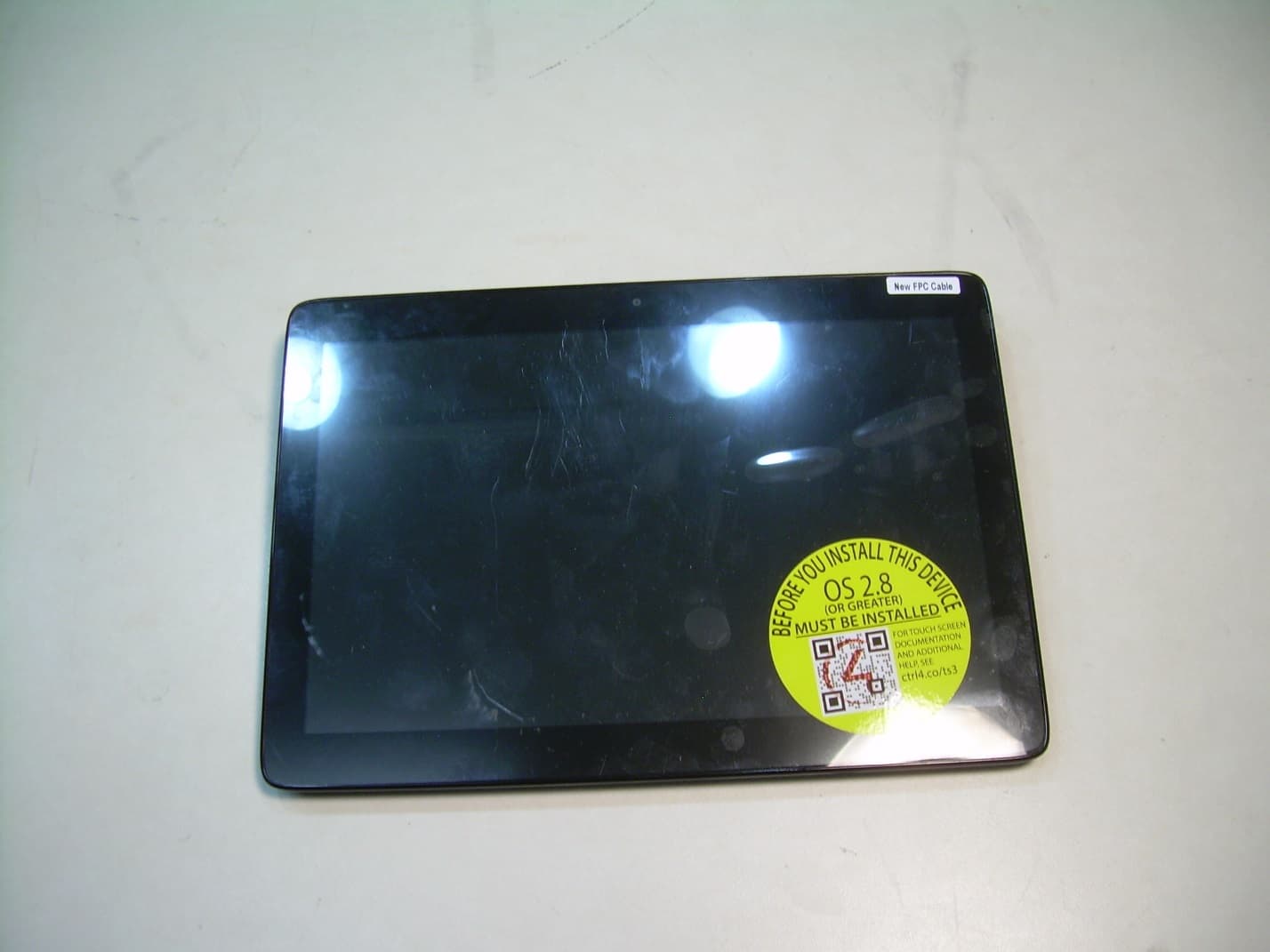
R33C4TT10
Jan 26, 2016Touchscreen Display for home automation system
Equipment Class
DTS - Digital Transmission System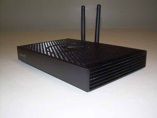
R33C4EA1
Jan 25, 2016Controller for home automation system
Equipment Class
DTS - Digital Transmission System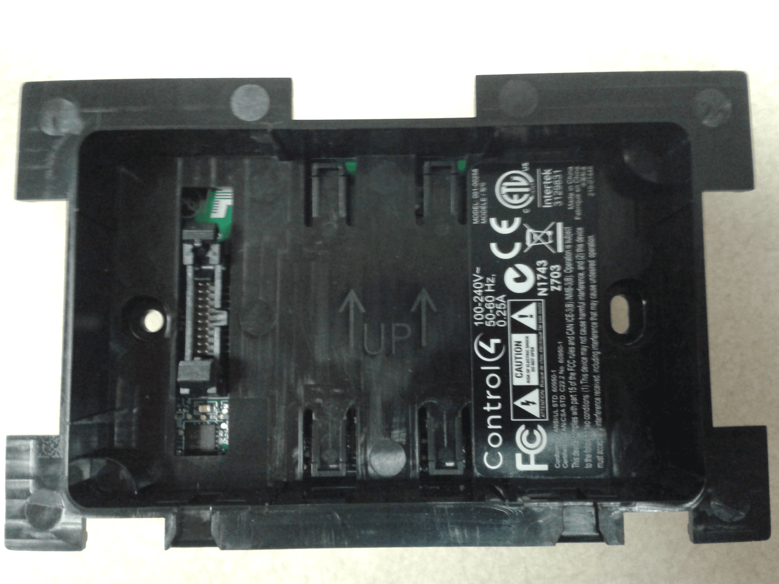
R33C4LGWM
Mar 24, 2015WIFI MODULE
Equipment Class
DTS - Digital Transmission System
R33C4SR260
Mar 18, 2015Remote control
Equipment Class
DTS - Digital Transmission System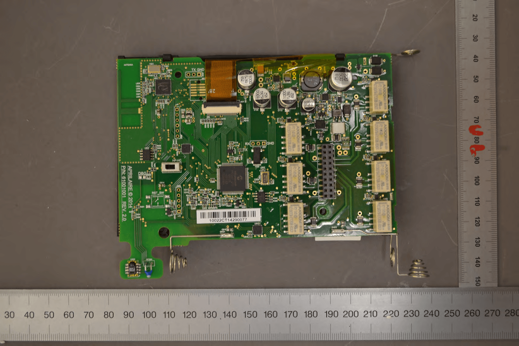
R33C4THERM
Feb 09, 2015THERMOMETER
Equipment Class
DTS - Digital Transmission System