R33D1Energy Controller
Snap One, LLC
Click to zoom
Application Details
- Equipment Class
- DTS - Digital Transmission System
- Date of Grant
- Jan 06, 2011
- Application Purpose
- Original Equipment
- Date of Application
- Jan 06, 2011
- Equipment Note
- Energy Controller
- Frequency Range
- 2405.00000000 - 2480.00000000
- Company
- Snap One, LLC
- Country
- United States
Documents & Files
Document Text
Text extracted from the exhibit documents filed with the FCC. Open a document above to read the original.
Users Manual
EC-100 Energy Controller User Guide Supported Models C4-EC100 Energy Controller Associated SKUs: • C4-EC100-BL — EC-100 Energy Controller, Black• C4-EC100-WH — EC-100 Energy Controller, White Introducing the EC-100 Energy ControllerThe Control4® EC-100 Energy Controller (EC-100) wirelessly connects to your home’s Smart Meter and gathers information about how much energy you are using and how much that energy use is costing you. And if you know how much energy you’re using, the Energy Controller can help you conserve energy and save money. The EC-100 comes with a colorful touch screen on which you can view current and past data about your home’s energy use in a clean, graphical format. Beyond that, the EC-100 provides an easy way to program and control your WT-100 Wireless Thermostat (sold separately), check your weather forecast, review your power bills, view messages about utility-driven energy savings events, and more! Congratulations on receiving your new EC-100 Energy Controller! EC-100 Features • Sleek 4.7” Color Touch Screen : The EC-100’s touch screen puts your home’s en- ergy management and control at your fi ngertips by allowing you to interact with data and controls for the electricity-consuming devices in your home. • Displays Your Home’s Electricity Use : Wirelessly communicates with your home’s Smart Meter to gather information about your home’s electricity use. This display lets you see your energy use over time, and shows you breakdowns of electricity use by device: heating and cooling, refrigerator, and more. • Broadband-Connected : The EC-100 connects to your home’s WiFi network to provide additional information including power bills, messages from your utility company and your local weather forecast. • Easy Thermostat Programming and Control : The EC-100 makes it easy to program your WT-100 Wireless Thermostat (sold separately), turn your heat or air conditioner on or off, or change the temperature in your home. You can also easily set your Wireless Thermostat into a special energy-saving ‘Vacation’ mode when you leave town. • Utility Bills : View and compare your monthly utility bills if available from your utility company. • Additional Resources : Refer to the EC-100 Energy Controller Setup Guide for additional information about setting up and con fi guring your new EC-100 Energy Controller. Battery Installation and Replacement Safety Rules • Use typical AA Alkaline batteries only. • Do not mix battery types, such as Alkaline and rechargeable NiMH batter- ies. • Do not mix used batteries with fresh batteries. • Do not attempt to recharge a battery unless the battery is speci fi cally marked “rechargeable.” • Never dispose of batteries in a fi re. WARNING! To prevent a battery short, leakage or rupture: • Utilisez les accumulateurs alcalins typiques d’AA seulement.• Ne mé langez pas les types de batterie, tels que les batteries alkalines et rechargeables de NiMH. • Ne mé langez pas des batterie frais avec des batterie ancien. • N’essayez pas de recharger une batterie à moins que la batterie soit spé ci fi quement marqué « rechargeable ». • Ne vous dé barassez jamais des batteries dans un feu. ATTENTION! Pour empê cher court-circuiter, fuite ou rupture de batterie: Battery Use and Care Tips • Keep the battery contacts and compartment clean. • Remove the batteries from the product if it is not going to be used for several months. • Extreme temperatures reduce battery performance. Avoid putting the EC-100 in very warm places. Use a small Phillips screwdriver to remove the screws and cover. Insert the three (3) AA Alkaline batteries (included with the product) into the bottom of the product (see fi gures below). Note : Ensure that you insert them according to the diagram provided in the battery compartment (with the + and - terminals aligned correctly). Install Batteries Terms Term De fi nition EC-100 The EC-100 Energy Controller is a table top or counter top display that lets you view your home’s energy usage data and control your WT-100 Wireless Thermostat. WT-100 Your WT-100 Wireless Thermostat controls the heating and air-condition- ing (HVAC) systems in your home. Current Temp The current temperature indicated on the thermostat inside the home. Set Temp Your set temperature is your desired temperature. You can program your desired temperatures for different times of day using the programming feature on the EC-100 or manually adjust your set temperature on either the EC-100 or WT-100 Wireless Thermostat. Hold When you manually adjust your set temperature, your selection will automatically hold or maintain your new set temperature for two (2) hours. All holds are two hours except for Vacation hold which will hold your Vacation set temperature until you cancel the Vacation hold. Mode The WT-100 can operate in up to seven (7) modes (Heat + Fan Auto, Heat + Fan On, Cool + Fan Auto, Cool + Fan On, Fan On, Emergency Heat (Heat Pump only), and Off). In any mode that the Fan is selected as On, the fan will run continuously. In Fan only mode, the fan will run continuously without using your heating or air-conditioning. For more de-tails and other modes, see “Changing the Thermostat Mode and Fan set-tings” section in the Control4 WT-100 Wireless Thermostat User Guide . Energy Event A utility-driven Demand Response event which leads to a temporary adjustment of your thermostat’s setting to reduce overall electricity consumption during peak periods of energy consumption. EC-100 Home Screen Control4 Main Menu. Tap Menu on most screens to access the Main Menu screen.Messages. Tap to view a list of messages from your power company. Energy Event Indicator. Appears during Energy Savings Events initiated by your utility company. Weather. View the current weather. Tap to access the Weather app.Note : The Home pro fi le must be con fi gured for the Weather app to work. Inside Temp. View the current inside temp of the Main Thermostat. Tap to change the Thermostat Set Temp or program your T…
Text truncated - open the document above for the full version.
Cover Letter(s)
11734 South Election Drive Suite 200 Draper, Utah 84020 (801) 523-3100 To: Federal Communications Commission Date:12/10/2010 445 12 th Street, SW Washington, DC 20554 Re: Non disclosure Request for FCC ID: R33D1 We are requesting that the following documents be held and treated as confidential and proprietary information. These materials contain technical trade secret information and should be guarded from competitors as stated under the Code of Federal Regulations Title 47 Section 0.459 (3), (4) and (5). 1) Schematic 2) Block Diagrams 3) Operational Description Ajit Sampalli Compliance/Component Engineer Control4 Technologies
External Photos
Front View of the EUT Back View of the EUT
RF Exposure Info
1 MPE Calculations FCC ID:R33D1 IC ID: 7848A-D1 2 1.0 SCOPE_________________________________________________________3 2.0 REVISION LEVEL_______________________________________________3 3.0 REFERENCE DOCUMENTS______________________________________3 4.0 CALCULATIONS________________________________________________4 5.0 CONCLUSION___________________________________________________4 1.0 SCOPE: This Report Demonstrates Evaluation and Compliance to the following standards: 1. Code of Federal Regulations Title 47, Volume 1, Section 1.1310. 2. Radio Frequency Exposure Compliance of Radiocommunication Apparatus (All Frequency Bands) - RSS-102 Issue 3 2.0 REVISION LEVEL: DATE COMMENTS REVISION 10/10/08 Created. 1.0 08/16/10 Added RSS-102 references 2.0 3.0 REFERANCE DOCUMENTS: (A) Limits for Maximum Permissible Exposure (MPE). Code of Federal Regulations Title 47, Volume 1, Section 1.1310. (B) Evaluating Compliance with FCC Guidelines for Human Exposure to Radiofrequency Electromagnetic Fields. OET Bulletin 67 Edition 97-01. (C) Radio Frequency Exposure Compliance of Radiocommunication Apparatus (All Frequency Bands) - RSS-102 Issue 3 3 4.0 CALCULATIONS: The following worst case emissions can be calculated by two methods Method 1: Based on a PPt (Peak Power Total) measurement of the total power into the antenna and the worst case antenna gain. Effective/Equivalent Isotropic Radiated Power [EIRP] dBm = Total power into the antenna [dBm] + antenna gain [dBi] To convert the values from dBm to mW mW = 10 dBm/10 [Or use the link http://www.aubraux.com/design/dbm-to-milli-watts- calculator.php] Method 2: Based on the radiated field strength measurement at 3 meters [at a calibrated OATS site, maximizing the antenna polarity and height] To convert the values from dBμV/m to EIRP [mW] use the link http://www.compeng.com.au/emc_conversion_tables_power_calculator.aspx After obtaining the EIRP, the Power density is calculated and compared against the FCC and IC limits. S FCC = Power density in mW/ cm² for FCC S FCC = EIRP/4π∙R² [4π∙R² = 5028 for R=20 cm] EIRP = Equivalent isotropically radiated power (mW) R = Distance to the center of radiation of the antenna (20 cm) S IC = Power density in W/ m² for IC S IC = EIRP/4π∙R² [4π∙R² = 0.5028 for R=0.2 m] EIRP = Equivalent isotropically radiated power in watts (W) [1 mW = 0.001W] R = Distance to the center of radiation of the antenna (0.2 m) [20 cm = 0.2 m] Radio dBuV@3m EIRP mW Sfcc Sic 260 103 5.98 .0012 .012 357 102 4.75 .00094 .0094 WiFi (B) 89 0.24 .000048 .00048 WiFi (G) 93 0.60 .00012 .0012 5.0 CONCLUSION: 1. Based upon the limits for Maximum Permissible Exposure (MPE) given in Table 1 of reference document (A) as 1mW/cm², this device falls under the required limits. 2. Based upon the limits given in section 4.2 of the reference document (C) as 10W/m², this device falls under the required limits.
Test Report
Nemko-CCL, Inc. 1940 West Alexander Street Salt Lake City, UT 84119 801-972-6146 Test Report Certification Test Of: C4-EC100 FCC ID: R33D1 Test Specifications: FCC PART 15, Subpart C Test Report Serial No: 161378-2.1 Applicant: Control4 11734 S. Election Road, Suite 200 Draper, UT 84020 Dates of Test: April 28, 2010 May 4, 2010 June 14, 23, & 29, 2010 August 4, 9, & 10, 2010 Issue Date: November 23, 2010 Accredited Testing Laboratory By: NVLAP Lab Code 100272-0 Nemko-CCL, Inc. TEST REPORT: 161378-2.1 FCC ID#: R33D1 Page 2 of 92 CERTIFICATION OF ENGINEERING REPORT This report has been prepared by Nemko-CCL, Inc. to document compliance of the device described below with the requirements of Federal Communications Commission (FCC) Part 15, Subpart C. This report may be reproduced in full, partial reproduction may only be made with the written consent of the laboratory. The results in this report apply only to the sample tested. - Applicant: Control4 - Manufacturer: Control4 - Brand Name: Control4 - Model Number: C4-EC100 - FCC ID Number: R33D1 On this 23 rd day of November 2010, I, individually, and for Nemko-CCL, Inc., certify that the statements made in this engineering report are true, complete, and correct to the best of my knowledge, and are made in good faith. Although NVLAP has recognized that the Nemko-CCL, Inc. EMC testing facilities are in good standing, this report must not be used to claim product certification, approval, or endorsement by NVLAP, NIST, or any agency of the federal government. Nemko-CCL, Inc. Tested by: Norman P. Hansen EMC Technician Nemko-CCL, Inc. TEST REPORT: 161378-2.1 FCC ID#: R33D1 Page 3 of 92 TABLE OF CONTENTS PAGE SECTION 1.0 CLIENT INFORMATION .................................................................................4 SECTION 2.0 EQUIPMENT UNDER TEST (EUT) .................................................................5 SECTION 3.0 TEST SPECIFICATION, METHODS & PROCEDURES .............................8 SECTION 4.0 OPERATION OF EUT DURING TESTING ..................................................14 SECTION 5.0 SUMMARY OF TEST RESULTS ...................................................................15 SECTION 6.0 802.11b/g TRANSCEIVER – MEASUREMENTS AND RESULTS .............16 SECTION 7.0 ZIGBEE #1 TRANSCEIVER – MEASUREMENTS AND RESULTS .........40 SECTION 8.0 ZIGBEE #2 TRANSCEIVER – MEASUREMENTS AND RESULTS .........53 APPENDIX 1 TEST PROCEDURES AND TEST EQUIPMENT ..........................................66 APPENDIX 2 PHOTOGRAPHS ................................................................................................74 APPENDIX 3 MANUFACTURER’S STATEMENT/ATTESTATION .................................91 APPENDIX 4 TRANSMITTER DUTY CYCLE CALCULATIONS .....................................92 Nemko-CCL, Inc. TEST REPORT: 161378-2.1 FCC ID#: R33D1 Page 4 of 92 SECTION 1.0 CLIENT INFORMATION 1.1 Applicant: Company Name: Control4 11734 S. Election Road, Suite 200 Draper, UT 84020 Contact Name: Ben Lindow Title: Engineer 1.2 Manufacturer: Company Name: Control4 11734 S. Election Road, Suite 200 Draper, UT 84020 Contact Name: Ben Lindow Title: Engineer Nemko-CCL, Inc. TEST REPORT: 161378-2.1 FCC ID#: R33D1 Page 5 of 92 SECTION 2.0 EQUIPMENT UNDER TEST (EUT) 2.1 Identification of EUT: Brand Name: Control4 Model Number: C4-EC100 Serial Number: None 2.2 Description of EUT: The C4-EC100 is a home energy interface device in a 5” x 3.5” x 2.5” plastic enclosure. The C4-EC100 provides a touch screen interface from the user to the smart meter on his home for energy usage related information. When the C4-EC100 is used with the C4-WT100 Thermostat, it allows for remote control of the thermostat. The C4-EC100 contains an 802.11b/g transceiver and two Zigbee transceivers. The C4-EC100 was tested using 5 power supplies that supply power to the USB port of the C4-EC100. The power supplies used in testing were the FranMar DSC-6PFA-05, FranMar DSA-12PFA-05, Friwo 15.2980, Something High P12- 050150US, and Sparkle FSP010-DWDA1. 2 AA batteries supply power in the event of a power outage. The C4-EC100 802.11b/g transceiver uses 11 channels in the 2400 to 2483.5 MHz frequency range. The antenna is a trace on the PCB. See the table below. Channel Frequency (MHz) Channel Frequency (MHz) Channel Frequency (MHz) 1 2412 5 2432 9 2452 2 2417 6 2437 10 2457 3 2422 7 2442 11 2462 4 2427 8 2447 Testing was performed at the upper, middle, and lower channels using both “B” and “G” and data rates of 5.5, 11, and 48 mbps were used for the test results shown in this report. The C4-EC100 Zigbee transceivers use 16 channels in the 2400 to 2483.5 MHz frequency range. The antennas are traces on the PCB. See the table of frequencies below. Channel Frequency (MHz) Channel Frequency (MHz) Channel Frequency (MHz) Channel Frequency (MHz) 11 2405 15 2425 19 2445 23 2465 12 2410 16 2430 20 2450 24 2470 13 2415 17 2435 21 2455 25 2475 14 2420 18 2440 22 2460 26 2480 Nemko-CCL, Inc. TEST REPORT: 161378-2.1 FCC ID#: R33D1 Page 6 of 92 This report covers the circuitry of the devices subject to FCC Part 15, Subpart C. The circuitry of the device subject to FCC Subpart B is covered in Nemko-CCL, Inc. report #161378- 1.1. 2.3 EUT and Support Equipment: The FCC ID numbers for all the EUT and support equipment used during the test are listed below: Brand Name Model Number Serial Number FCC ID Number or Compliance Description Name of Interface Ports / Interface Cables BN: Control4 MN: C4-EC100 SN: None R33D1 Home Energy Interface See Section 2.4 2.4 Interface Ports on EUT: There are no interface ports on the EUT. All communication is via the 802.11b/g or Zigbee transceivers. 2.5 Modification Incorporated/Special Accessories on EUT: The following modifications were made to the C4-EC100 by the Client during testing to comply with the specification. This report is not complete without an accompanying signed attestation, included as Appendix 4, that the product will have all of the documented modificati…
Text truncated - open the document above for the full version.
Test Setup Photos
Front View Radiated Disturbance Worst Case Configuration Back View Radiated Disturbance Worst Case Configuration Front View Conducted Disturbance Worst Case Configuration Back View Conducted Disturbance Worst Case Configuration
Contact Information
Applicant
Roger J Midgley(Principle Compliance Engineer)
Technical Contact
Control4James Russell
[email protected]801 523 3100
11734 S. Election Drive, Suite 200 · Draper, Utah · United States
Non-Technical Contact
Control4Ajit Sampalli
[email protected]801 523 3187
Test Firm
VPI TechnologyJason Stewart
[email protected]801-495-2310
Technical Specifications
| # | Rule Parts | Frequency Range | Power Output |
|---|---|---|---|
| 3 | 15C | 2.40 GHz - 2.48 GHz | 28.80 mW |
Other Applications from Snap One, LLC
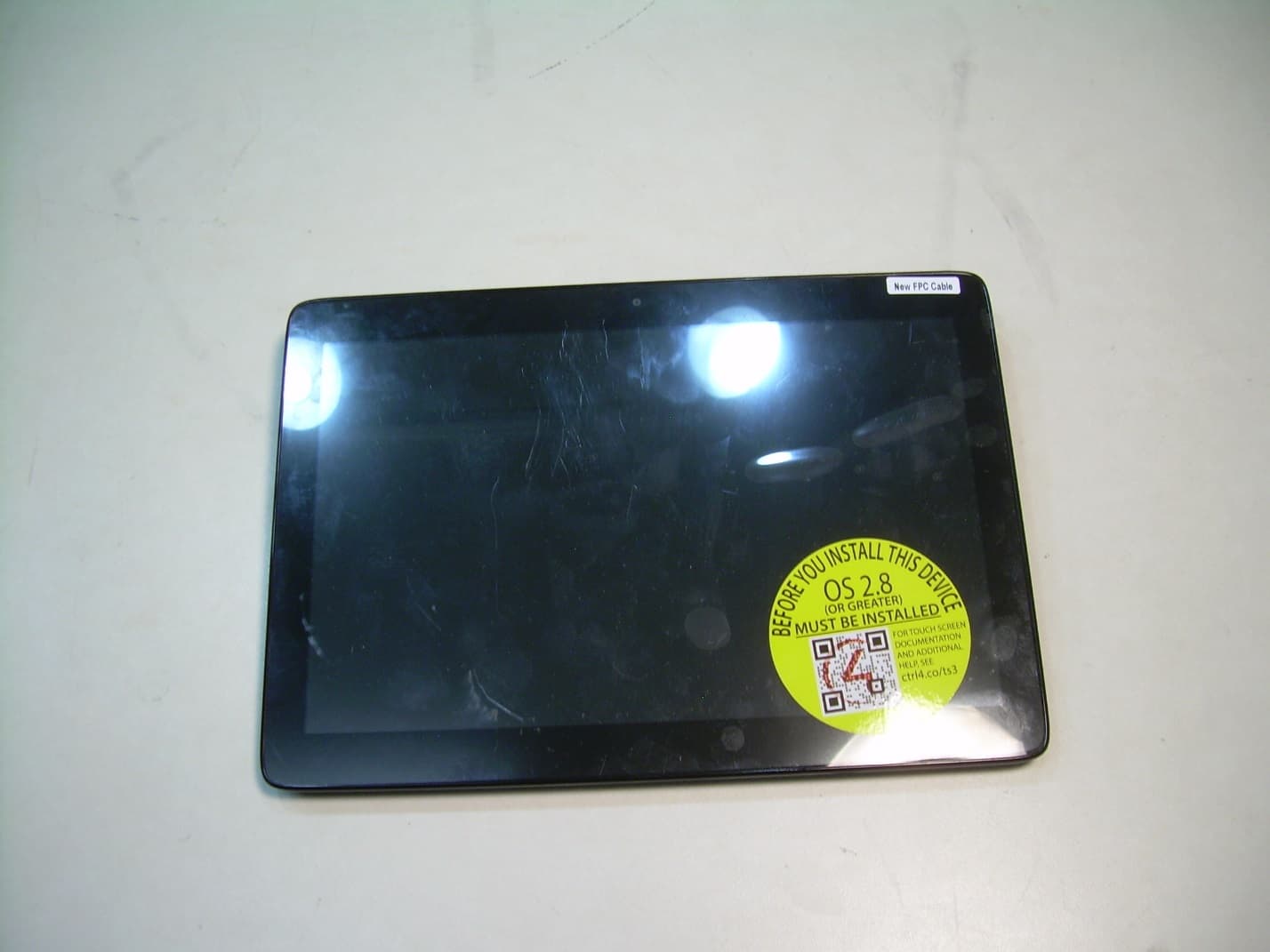
R33C4TT10
Jan 26, 2016Touchscreen Display for home automation system
Equipment Class
DTS - Digital Transmission System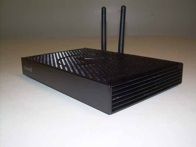
R33C4EA1
Jan 25, 2016Controller for home automation system
Equipment Class
DTS - Digital Transmission System
R33C4LGWM
Mar 24, 2015WIFI MODULE
Equipment Class
DTS - Digital Transmission System
R33C4SR260
Mar 18, 2015Remote control
Equipment Class
DTS - Digital Transmission System
R33C4THERM
Feb 09, 2015THERMOMETER
Equipment Class
DTS - Digital Transmission System