R33D2InfinityEdge Touch Screen
Snap One, LLC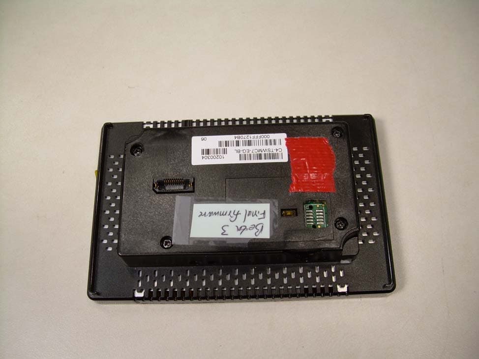
Click to zoom
Application Details
- Equipment Class
- DTS - Digital Transmission System
- Date of Grant
- Sep 29, 2010
- Application Purpose
- Original Equipment
- Date of Application
- Sep 29, 2010
- Equipment Note
- InfinityEdge Touch Screen
- Frequency Range
- 2412.00000000 - 2462.00000000
- Company
- Snap One, LLC
- Country
- United States
Documents & Files
Document Text
Text extracted from the exhibit documents filed with the FCC. Open a document above to read the original.
Users Manual
InfinityEdge™ 5” and 7” In-Wall Touch Screen Installation Guide Supported Models • C4-TSWMC5 – InfinityEdge™ 5” In-Wall Touch Screen • C4-TSWMC7 – InfinityEdge™ 7” In-Wall Touch Screen • Associated SKUs: • C4-TSWMC5-EG-WH – InfinityEdge™ 5” In-Wall Touch Screen, White • C4-TSWMC5-EG-BL – InfinityEdge™ 5” In-Wall Touch Screen, Black • C4-TSWMC7-EG-WH – InfinityEdge™ 7” In-Wall Touch Screen, White • C4-TSWMC7-EG-BL – InfinityEdge™ 7” In-Wall Touch Screen, Black What’s in the Box Carefully unpack the contents of the box, and make sure the following items are included in the box. If any item is missing or damaged, please contact your Control4 Reseller. • InfinityEdge™ 5” or 7” In-Wall Touch Screen • InfinityEdge™ power box (used to power the Touch Screen) • Two (2) Orange wire nuts • InfinityEdge™ 5” and 7” In-Wall Touch Screens Installation Guide (this document) Important Safety Instructions WARNING! The Touch Screen must be protected by an external circuit breaker or a fuse rated at 6A maximum when used in Europe. Avertissement! Pour réduire le risque du feu ou de choc électrique, n’exposez pas cet appareil à la pluie ou à l’humidité. Warnung! Die Berührungseingabe muß durch einen externen Circuit breaker oder eine Sicherung geschützt werden, die am Maximum 6A veranschlagen wird, wenn sie in Europa verwendet wird. Important! Do not use pens or sharp objects to navigate or make selec- tions on the Touch Screen. To select an item or scroll through a list, use your fingertip. Important! N’employez pas les stylos ou les objets pointus pour diriger ou pour faire des choix sur l’écran. Pour choisir un article ou un rouleau par une liste, employez votre bout du doigt. Wichtig! Benutzen Sie nicht Federn oder scharfe Gegenstände, um oder Vorwähleren auf dem Schirm zu bilden zu steuern. Um ein Einzelteil oder eine Rolle durch eine Liste vorzuwählen, benutzen Sie Ihre Fingerspitze. Important! Improper use or installation can cause LOSS/DAMAGE OF PROPERTY. Important! L’utilisation ou l’installation inexacte peut causer LOSS/DAMAGE DE PROPRIÉTÉ. Wichtig! Unsachgemäßer Gebrauch oder Installation können LOSS/DAM- AGE DER EIGENSCHAFT verursachen. Important! Using this product in a manner other than outlined in this docu- ment voids your warranty. Further, Control4 is NOT liable for any damage incurred with the misuse of this product. See “Warranty.” Important! Utilisant ce produit en quelque sorte autre que décrit dans ce document vide votre garantie. De plus, Control4 n’est pas responsable d’aucun dommage encouru avec l’abus de ce produit. Voyez que «Warranty.» Wichtig! Das Verwenden dieses Produktes in gewissem Sinne anders als umrissen in diesem Dokument hebt Ihre Garantie auf. Weiter ist Control4 NICHT für irgendeine Beschädigung verantwortlich, die mit der Fehlanwend- ung dieses Produktes genommen wird. Sehen Sie, daß “Warranty.” Introduction The Control4 ® InfinityEdge™ 5” or 7” In-Wall Touch Screens offer complete system control in an elegant and compact design. These Touch Screens are equipped with a capacitive Touch Screen surface and four (4) programmable shortcut buttons, and are available with AC power for wireless connections and Power-Over-Ethernet (PoE) for Ethernet connec- tions. Available for new construction or retrofits. Accessories • Control4 Power Over Ethernet Injector, sold separately (AC-POE1-B) • InfinityEdge™ 5” and 7” In-Wall Touch Screens Wall Box New Construction, Plastic • (C4-NWB57C-P) • InfinityEdge™ 5” and 7” In-Wall Touch Screens Wall Box New Construction, Metal • (C4-NWB57C-M) • InfinityEdge™ 5” and 7” In-Wall Touch Screens Wall Box Retrofit, Plastic (C4-RWB57C-P) • InfinityEdge™ 5” and 7” In-Wall Touch Screen Wall Box Retrofit, Metal (C4-RWB57C-M) New Device AC Power (unless using PoE) Option 1: Ethernet Connection with a PoE Injector or a Third-Party Injector or Switch PoE injects electrical current into the Ethernet cable using a PoE Injector (model #AC-POE1-B) or a third-party PoE solution to provide the Touch Screen with power and a network connection. The InfinityEdge™ 5” and 7” Touch Screens work with a PoE Injector or a third-party PoE Injector. If you plan to use a third-party PoE solution, see “Installa- tion.” To set up your PoE and Ethernet connection with a PoE Injector, see Figure 2. Figure 2. Ethernet Model - Requires Ethernet Connection to PoE Injector Place the PoE Injector near your gateway/router/switch. Pull the Ethernet cable from that location to where you want to install the Touch Screen. Option 2: Ethernet Connection with AC No PoE Injector is needed for Ethernet with AC power; the Ethernet is connected directly to the switch. This power connection requires both neutral and hot connections (see Figure 3). Option 3: WiFi Connection with AC WiFi placement: Place the Touch Screen above a power source, such as an outlet. En- sure that you have WiFi in the home (see Figure 4). Figure 4. WiFi - Requires AC Power and WAP Wall Box Kit Options There are four (4) wall box options available to install this Touch Screen. Metal and plastic wall boxes are available for new construction or retrofit installations. • InfinityEdge™ 5” or 7” In-Wall Touch Screen Wall Box Kits - New Construction Plastic Model (C4-NWB57C-P) Metal Model (C4-NWB57C-M) • InfinityEdge™ 5” or 7” In-Wall Touch Screen Wall Box Kit - Retrofit Plastic Model (C4-RWB57C-P) Metal Model (C4-RWB57C-M) Refer to the Control4 InfinityEdge 5” or 7” In-Wall Touch Screen Wall Box Installation Guide - New Construction or InfinityEdge 5” or 7” In-Wall Touch Screen Wall Box Installa- tion Guide - Retrofit for your wall box installation instructions. Placement, Network Connection, and Power Options Place the Touch Screen in a convenient location at eye level, typically near the entrance of the room, approximately 57 to 61 inches from the floor (see Figure 1). WARNING! Do not place the Touch Screen near sources of heat or expose to direct sunlight for an extended period of time. Avertissement! Ne placez pas l…
Text truncated - open the document above for the full version.
Cover Letter(s)
11734 South Election Road, Ste. 200 | Salt Lake City, Utah 84020 | www.control4.com | 801.523.3100 phone | 801.523.3199 fax September 22, 2010 To: Federal Communications Commission 445 12 th Street, SW Washington, DC 20554 Reference: Non disclosure Request for FCC ID R33D2 We are requesting that the following documents be held and treated as confidential and proprietary information. These materials contain technical trade secret information and should be guarded from competitors as stated under the Code of Federal Regulations Title 47 Section 0.459 (3), (4) and (5). 1. Schematic 2. Block Diagrams 3. Operational Description Thank you, Ajit Sampalli Compliance/Component Engineer Control4 Inc.
External Photos
Front View of the Display Unit Back View of the Display Unit
Internal Photos
View of the Component Side of the Display PCB showing Ferrite on Flex Cable View of the Interface Side of the Display PCB View of the Component Side of the Main PCB View of the Circuitry Under the RF Shielding View of the Power Supply/Interface Module with Display Removed View of the Interface Side of the Power Supply/Interface PCB with Heatsink in Place View of the Interface Side of the Power Supply/Interface PCB with Heatsink Removed View of the Component Side of the Power Supply/Interface PCB with Heatsink in Place View of the Component Side of the Power Supply/Interface PCB with Heatsink Removed
RF Exposure Info
1 MPE Calculations FCC ID: R33D2 IC ID: 7848A-D2 2 1.0 SCOPE_________________________________________________________3 2.0 REVISION LEVEL_______________________________________________3 3.0 REFERENCE DOCUMENTS______________________________________3 4.0 CALCULATIONS________________________________________________4 5.0 CONCLUSION___________________________________________________4 1.0 SCOPE: This Report Demonstrates Evaluation and Compliance to the following standards: 1. Code of Federal Regulations Title 47, Volume 1, Section 1.1310. 2. Radio Frequency Exposure Compliance of Radiocommunication Apparatus (All Frequency Bands) - RSS-102 Issue 3 2.0 REVISION LEVEL: DATE COMMENTS REVISION 10/10/08 Created. 1.0 08/16/10 Added RSS-102 references 2.0 3.0 REFERANCE DOCUMENTS: (A) Limits for Maximum Permissible Exposure (MPE). Code of Federal Regulations Title 47, Volume 1, Section 1.1310. (B) Evaluating Compliance with FCC Guidelines for Human Exposure to Radiofrequency Electromagnetic Fields. OET Bulletin 67 Edition 97-01. (C) Radio Frequency Exposure Compliance of Radiocommunication Apparatus (All Frequency Bands) - RSS-102 Issue 3 3 4.0 CALCULATIONS: The following worst case emissions was calculated by using Method 2 below Method 1: Based on a PPt (Peak Power Total) measurement of the total power into the antenna and the worst case antenna gain. Effective/Equivalent Isotropic Radiated Power [EIRP] dBm = Total power into the antenna [dBm] + antenna gain [dBi] To convert the values from dBm to mW mW = 10 dBm/10 Method 2: Based on the radiated field strength measurement at 3 meters [at a calibrated OATS site, maximizing the antenna polarity and height] The worst case radiated field Strength when measured at 3 meters at the CCL Wanship facility, was 103.1 dBμV/m, peak detection vertical polarity while in the Wi-Fi “G” mode – power level at 14 Converting the 103.1 dBμV/m at 3 meters to EIRP = 6.12 mW or 0.00612 W After obtaining the EIRP, the Power density is calculated and compared against the FCC and IC limits. S FCC = Power density in mW/cm² for FCC S FCC = EIRP/4π∙R² EIRP = Equivalent isotropically radiated power (mW) R = Distance to the center of radiation of the antenna (20 cm) S FCC = 0.0012 mW/cm² S IC = Power density in W/m² for IC S IC = EIRP/4π∙R² EIRP = Equivalent isotropically radiated power in watts (W) R = Distance to the center of radiation of the antenna (0.2 m) S IC = 0.012 W/m² 5.0 CONCLUSION: 1. Based upon the limits for Maximum Permissible Exposure (MPE) given in Table 1 of reference document (A) as 1mW/cm², this device falls under the required limits. 2. Based upon the limits given in section 4.2 of the reference document (C) as 10W/m², this device falls under the required limits.
Test Report
Nemko-CCL, Inc. 1940 West Alexander Street Salt Lake City, UT 84119 801-972-6146 Test Report Certification Test Of: C4-TSWMC5 FCC ID: R33D2 Test Specifications: FCC PART 15, Subpart C Test Report Serial No: 157735-2.1 Applicant: Control4 11734 S. Election Road, Suite 200 Draper, UT 84020 Date of Test: July 27 and September 9, 2010 Issue Date: September 23, 2010 Accredited Testing Laboratory By: NVLAP Lab Code 100272-0 Nemko-CCL, Inc. TEST REPORT: 157735-2.1 FCC ID#: R33D2 Page 2 of 65 2 CERTIFICATION OF ENGINEERING REPORT This report has been prepared by Nemko-CCL, Inc. to document compliance of the device described below with the requirements of Federal Communications Commission (FCC) Part 15, Subpart C. This report may be reproduced in full, partial reproduction may only be made with the written consent of the laboratory. The results in this report apply only to the sample tested. - Applicant: Control4 - Manufacturer: Control4 - Brand Name: Control4 - Model Number: C4-TSWMC5 - FCC ID Number: R33D2 On this 23 rd day of September 2010, I, individually, and for Nemko-CCL, Inc., certify that the statements made in this engineering report are true, complete, and correct to the best of my knowledge, and are made in good faith. Although NVLAP has recognized that the Nemko-CCL, Inc. EMC testing facilities are in good standing, this report must not be used to claim product certification, approval, or endorsement by NVLAP, NIST, or any agency of the federal government. Nemko-CCL, Inc. Tested by: Norman P. Hansen EMC Technician Nemko-CCL, Inc. TEST REPORT: 157735-2.1 FCC ID#: R33D2 Page 3 of 65 3 TABLE OF CONTENTS PAGE SECTION 1.0 CLIENT INFORMATION .................................................................................4 SECTION 2.0 EQUIPMENT UNDER TEST (EUT) .................................................................5 SECTION 3.0 TEST SPECIFICATION, METHODS & PROCEDURES .............................8 SECTION 4.0 OPERATION OF EUT DURING TESTING ..................................................14 SECTION 5.0 SUMMARY OF TEST RESULTS ...................................................................15 SECTION 6.0 MEASUREMENTS, EXAMINATIONS AND DERIVED RESULTS ..........16 APPENDIX 1 TEST PROCEDURES AND TEST EQUIPMENT ..........................................40 APPENDIX 2 PHOTOGRAPHS ................................................................................................48 APPENDIX 3 MANUFACTURER’S STATEMENT/ATTESTATION .................................65 Nemko-CCL, Inc. TEST REPORT: 157735-2.1 FCC ID#: R33D2 Page 4 of 65 4 SECTION 1.0 CLIENT INFORMATION 1.1 Applicant: Company Name: Control4 11734 S. Election Road, Suite 200 Draper, UT 84020 Contact Name: Troy Huebner Title: Engineer 1.2 Manufacturer: Company Name: Control4 11734 S. Election Road, Suite 200 Draper, UT 84020 Contact Name: Troy Huebner Title: Engineer Nemko-CCL, Inc. TEST REPORT: 157735-2.1 FCC ID#: R33D2 Page 5 of 65 5 SECTION 2.0 EQUIPMENT UNDER TEST (EUT) 2.1 Identification of EUT: Brand Name: Control4 Model Number: C4-TSWMC5 Serial Number: None 2.2 Description of EUT: The C4-TSWMC5 is a 5‖ display with capacitive touchscreen for use in Control4 home automation and security systems. The C4-TSWMC5 may be powered by the AC mains or by power over the Ethernet port. Configurations using both power options were tested. For POE power, an Ault PW130 power supply/injector was used to power the C4-TSWMC5. The C4- TSWMC5 has an 802.11b/g transceiver and an Ethernet port for interfacing the Control4 system. The C4-TSWMC5 uses 11 channels in the 2400 to 2483.5 MHz frequency range. The antenna is a trace on the PCB. See the table below. Channel Frequency (MHz) Channel Frequency (MHz) Channel Frequency (MHz) 1 2412 5 2432 9 2452 2 2417 6 2437 10 2457 3 2422 7 2442 11 2462 4 2427 8 2447 Testing was performed at the upper, middle, and lower channels using both ―B‖ and ―G‖ and data rates of 5.5, 11, and 48 mbps were used for the test results shown in this report. This report covers the circuitry of the devices subject to FCC Part 15, Subpart C. The circuitry of the device subject to FCC Subpart B is covered in Nemko-CCL, Inc. report #157735- 1.1. 2.3 EUT and Support Equipment: The FCC ID numbers for all the EUT and support equipment used during the test are listed below: Nemko-CCL, Inc. TEST REPORT: 157735-2.1 FCC ID#: R33D2 Page 6 of 65 6 Brand Name Model Number Serial Number FCC ID Number or Compliance Description Name of Interface Ports / Interface Cables BN: Control4 MN: C4-TSWMC5 (Note 1) SN: None R33D2 Display/ Touchscreen See Section 2.4 BN: TRENDnet MN: TEG-S50TXE SN: None DoC 5 port Ethernet Hub Ethernet/Cat5 cable (Note 2) BN: Ault MN: PW130 SN: None DoC POE Supply/Injector Ethernet/Cat 5e cable Ethernet with Power/Cat 5e cable (Note 2) BN: Dell MN: Latitude SN: None DoC Computer Ethernet/Cat 5e cable Note: (1) EUT (2) Interface port connected to EUT (See Section 2.4) The support equipment listed above was not modified in order to achieve compliance with this standard. 2.4 Interface Ports on EUT: Name of Ports No. of Ports Fitted to EUT Cable Descriptions/Length AC 1 2 Conductor power cord/1.5 meter Ethernet 1 Cat 5e cable/7 meters Nemko-CCL, Inc. TEST REPORT: 157735-2.1 FCC ID#: R33D2 Page 7 of 65 7 2.5 Modification Incorporated/Special Accessories on EUT: The following modifications were made to the C4-TSWMC5 by the Client during testing to comply with the specification. This report is not complete without an accompanying signed attestation, included as Appendix 3, that the product will have all of the documented modifications incorporated into the product when manufactured and placed on the market. 1. A Steward 28R1654-000 ferrite was placed around the display/touchscreen flex cable. See Photograph 9 of Appendix 2. 2. A Steward 28A2025-0A2 ferrite was added to the Ethernet cable and the AC power lines at the EUT when powered from the AC mains. The ferrite on the AC mains was wrapped so the flying leads passed …
Text truncated - open the document above for the full version.
Test Setup Photos
Front View Radiated Disturbance – Worst-case Configuration Back View Radiated Disturbance – Worst-case Configuration Front View Conducted Disturbance – Worst-case Configuration Back View Conducted Disturbance – Worst-case Configuration Ferrite Placement on AC Mains Flying Leads Ferrite Placement on Ethernet Cable
Contact Information
Applicant
Roger J Midgley(Principle Compliance Engineer)
Technical Contact
Control 4James K Russell
[email protected]801 523 3100
11734 South Election Road, Suite 200 · Draper, Utah · United States
Non-Technical Contact
Control 4Ajit Sampali
[email protected]801 523 3187
Test Firm
VPI TechnologyJason Stewart
[email protected]801-495-2310
Technical Specifications
| # | Rule Parts | Frequency Range | Power Output |
|---|---|---|---|
| 1 | 15C | 2.41 GHz - 2.46 GHz | 18.00 mW |
Other Applications from Snap One, LLC
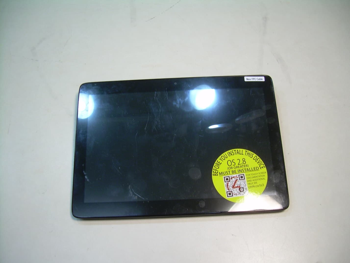
R33C4TT10
Jan 26, 2016Touchscreen Display for home automation system
Equipment Class
DTS - Digital Transmission System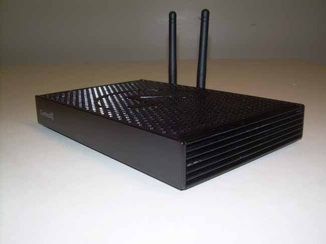
R33C4EA1
Jan 25, 2016Controller for home automation system
Equipment Class
DTS - Digital Transmission System
R33C4LGWM
Mar 24, 2015WIFI MODULE
Equipment Class
DTS - Digital Transmission System
R33C4SR260
Mar 18, 2015Remote control
Equipment Class
DTS - Digital Transmission System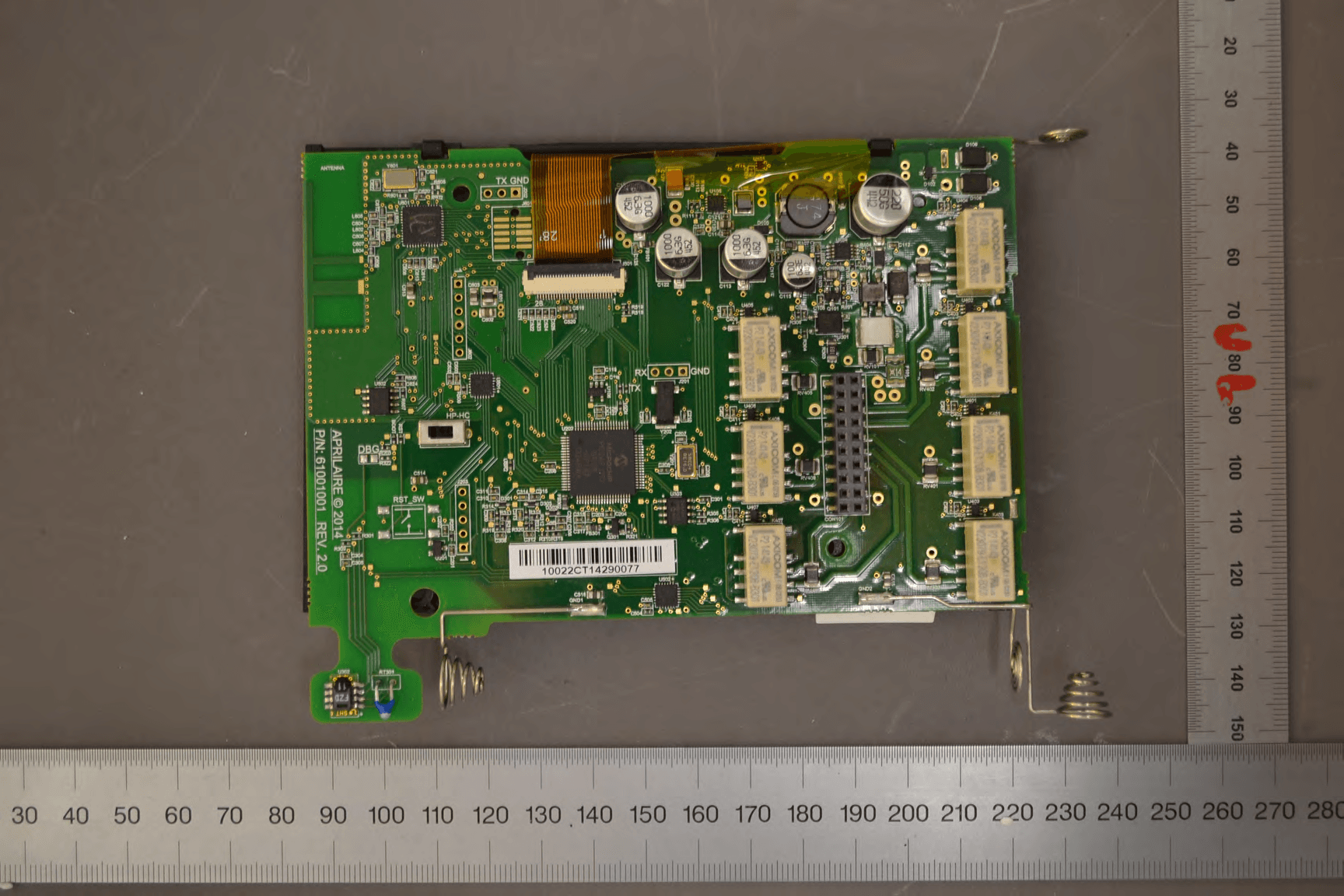
R33C4THERM
Feb 09, 2015THERMOMETER
Equipment Class
DTS - Digital Transmission System