R33H1WT-100 Wireless Thermostat
Snap One, LLC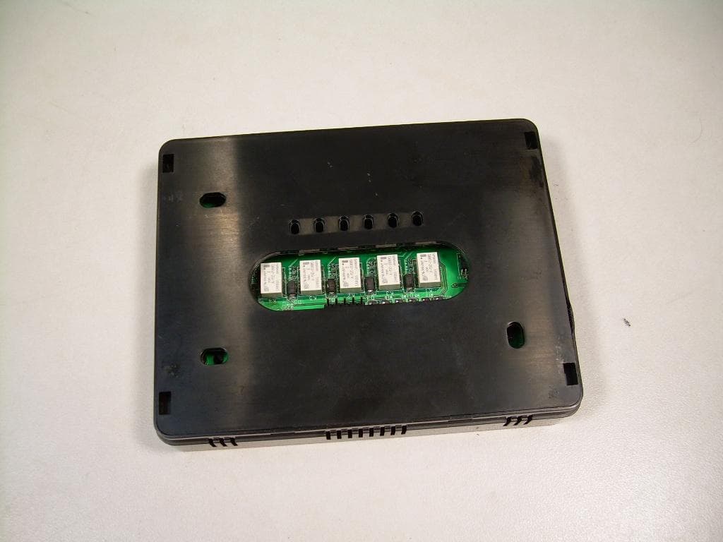
Click to zoom
Application Details
- Equipment Class
- DTS - Digital Transmission System
- Date of Grant
- May 27, 2010
- Application Purpose
- Original Equipment
- Date of Application
- May 27, 2010
- Equipment Note
- WT-100 Wireless Thermostat
- Frequency Range
- 2405.00000000 - 2475.00000000
- Company
- Snap One, LLC
- Country
- United States
Documents & Files
Document Text
Text extracted from the exhibit documents filed with the FCC. Open a document above to read the original.
Users Manual
Control4 WT-100 Wireless Thermostat User Guide 1 WT-100 Wireless Thermostat User Guide Congratulations on receiving your new WT-100 Wireless Thermostat! Your WT-100 thermostat works with your EC-100 Energy Controller to help manage your home’s energy use. About your WT-100 Thermostat Your WT-100 thermostat is designed to display the current temperature, mode (Heat, Cool, Fan, or Off), and program (Wake, Leave, Return, or Sleep). You may also use the WT-100 to view or change your current set temperature, or to change the mode. Your EC-100 Energy Controller has all the features of the WT-100 thermostat. The EC-100 Energy Controller should be used to make changes to the thermostat program or current set temperature, set a vacation hold, and view electricity usage and billing data. Control4 WT-100 Wireless Thermostat User Guide 2 Contents Overview ........................................................................................................................................................................................................................ 3 Terms ............................................................................................................................................................................................................................. 4 Viewing or Changing the Set Temperature .................................................................................................................................................................... 5 Changing the Mode ........................................................................................................................................................................................................ 6 Programming your Thermostat ..................................................................................................................................................................................... 7 Energy Events ................................................................................................................................................................................................................. 7 Regulatory Compliance .................................................................................................................................................................................................. 8 Recycling ........................................................................................................................................................................................................................ 9 Product Specifications.................................................................................................................................................................................................... 9 Control4 WT-100 Wireless Thermostat User Guide 3 Overview Mode—Heat, Cool, Fan or Off Battery—The battery icon will be displayed when the battery is low and needs replacing. A low-battery notification will also be displayed on the EC-100 Energy Controller. Connectivity-Shows that the WT-100 thermostat is communicating with the EC-100 Energy Controller. Program Indicator—Shows which pre-programmed time period is in effect. Energy Event—This message is displayed during a utility-driven energy savings event. Emergency Heat—Em Heat is displayed when emergency (supllementatl) heat is on. Current Temp/Set Temp— Your home’s current temperature is displayed here. To see the set temperature, press either the Up or Down button once to turn on the backlight and once more to view the set temperature. Press a third time to adjust the set temperature by one degree. Control4 WT-100 Wireless Thermostat User Guide 4 Terms EC-100: Your EC-100 Energy Controller is table or counter top display that lets you view your home’s energy usage data and control your WT-100 thermostat. WT-100: Your WT-100 thermostat communicates with the heating and air-conditioning (HVAC) systems in your home. Set Temperature: Your set temperature is your desired temperature. You can program your desired temperatures for different times of day using the programming feature on the EC-100 Energy Controller or manually adjust your set temperature on either the EC-100 Energy Controller or WT-100 thermostat. Hold: When you manually adjust your set temperature, your selection will automatically hold, or maintain your new set temperature, for two hours. All holds are two hours except for Vacation hold, which will hold your Vacation set temperature until you cancel the Vacation hold. Mode: The WT-100 can operate in four modes (Heat, Cool, Fan, and Off). In both Heat and Cool modes, the fan will run automatically when needed. In Fan mode, the fan will run continuously without using your heating or air-conditioning. Energy Event: An Energy Savings Event is a utility-driven demand response event which leads to a temporary adjustment of your thermostat set temperature to reduce overall electricity consumption during peak periods of energy consumption. Control4 WT-100 Wireless Thermostat User Guide 5 Viewing or Changing the Set Temperature Your home’s current temperature is displayed on the WT-100 thermostat. Press either the Up or Down button twice (1 st press turns on backlight) to temporarily display the set temperature in place of the current, actual temperature. Press the Up or Down button again to change the set temperature. Each press will change the temperature by one degree. Your new set temperature will be maintained for two hours. Control4 WT-100 Wireless Thermostat User Guide 6 Changing the Mode The Mode icon indicates which system is current running: Heat, Cool, Fan or Off. Pressing the Mode/Off button will cycle through the modes. To change the mode, press the Mode/Off button until your desired Mode is shown. Heat - Thermostat is controlling the heater, Fan is on Auto and the fan icon is displayed only when the fan is running. Fan - The fan is on…
Text truncated - open the document above for the full version.
External Photos
Front View of the EUT Back View of the EUT
Internal Photos
View of the EUT with Rear Cover Removed View of the Front of the PCB View of the Back of the PCB
Test Report
Nemko-CCL, Inc. 1940 West Alexander Street Salt Lake City, UT 84119 801-972-6146 Test Report Certification Test Of: C4-WT100 FCC ID: R33H1 Test Specifications: FCC PART 15, Subpart C Test Report Serial No: 2625 Applicant: Control4 11734 S. Election Road, Suite 200 Draper, UT 84020 Dates of Test: February 24 & 25, 2010 Issue Date: March 4, 2010 Accredited Testing Laboratory By: NVLAP Lab Code 100272-0 Nemko-CCL, Inc. TEST REPORT: 2625 FCC ID#: R33H1 Page 2 of 42 2 CERTIFICATION OF ENGINEERING REPORT This report has been prepared by Nemko-CCL, Inc. to document compliance of the device described below with the requirements of Federal Communications Commission (FCC) Part 15, Subpart C. This report may be reproduced in full, partial reproduction may only be made with the written consent of the laboratory. The results in this report apply only to the sample tested. - Applicant: Control4 - Manufacturer: Control4 - Brand Name: Control4 - Model Number: C4-WT100 - FCC ID Number: R33H1 On this 4 th day of March 2010, I, individually, and for Nemko-CCL, Inc., certify that the statements made in this engineering report are true, complete, and correct to the best of my knowledge, and are made in good faith. Although NVLAP has recognized that the Nemko-CCL, Inc. EMC testing facilities are in good standing, this report must not be used to claim product certification, approval, or endorsement by NVLAP, NIST, or any agency of the federal government. Nemko-CCL, Inc. Tested by: Norman P. Hansen EMC Technician Nemko-CCL, Inc. TEST REPORT: 2625 FCC ID#: R33H1 Page 3 of 42 3 TABLE OF CONTENTS PAGE SECTION 1.0 CLIENT INFORMATION .................................................................................4 SECTION 2.0 EQUIPMENT UNDER TEST (EUT) .................................................................5 SECTION 3.0 TEST SPECIFICATION, METHODS & PROCEDURES .............................8 SECTION 4.0 OPERATION OF EUT DURING TESTING ..................................................14 SECTION 5.0 SUMMARY OF TEST RESULTS ...................................................................15 SECTION 6.0 MEASUREMENTS, EXAMINATIONS AND DERIVED RESULTS ..........16 APPENDIX 1 TEST PROCEDURES AND TEST EQUIPMENT ..........................................30 APPENDIX 2 PHOTOGRAPHS ................................................................................................36 Nemko-CCL, Inc. TEST REPORT: 2625 FCC ID#: R33H1 Page 4 of 42 4 SECTION 1.0 CLIENT INFORMATION 1.1 Applicant: Company Name: Control4 11734 S. Election Road, Suite 200 Draper, UT 84020 Contact Name: Bobby Bruhn Title: Engineer 1.2 Manufacturer: Company Name: Control4 11734 S. Election Road, Suite 200 Draper, UT 84020 Contact Name: Bobby Bruhn Title: Engineer Nemko-CCL, Inc. TEST REPORT: 2625 FCC ID#: R33H1 Page 5 of 42 5 SECTION 2.0 EQUIPMENT UNDER TEST (EUT) 2.1 Identification of EUT: Brand Name: Control4 Model Name or Number: C4-WT100 Serial Number: None 2.2 Description of EUT: The C4-WT100 is a thermostat for use in the Control4 home automation systems. The C4-WT100 provides 6 conductors for interfacing the HVAC system. Interface to the Control4 home automation system is via buttons on the front panel or a 2.4 GHz Zigbee transceiver. The C4-WT100 is powered by 3 Vdc from 4 AA batteries. The Zigbee transceiver uses 15 channels in the 2400 to 2483.5 MHz band. The individual channels are shown in the following plots. dBm 0 -10 -20 -30 -40 -50 -60 -70 -80 -90 -100 T race A Start: 2.402500 GHzStop: 2.427500 GHz T race ALower 5 channels 1 1 2.405000 GHz -5.4000 dBm 2 2 2.410075 GHz -5.1000 dBm 3 3 2.415075 GHz -5.8000 dBm 4 4 2.420050 GHz -5.8000 dBm 5 5 2.425025 GHz -5.8000 dBm Nemko-CCL, Inc. TEST REPORT: 2625 FCC ID#: R33H1 Page 6 of 42 6 dBm 0 -10 -20 -30 -40 -50 -60 -70 -80 -90 -100 T race A Start: 2.427500 GHzStop: 2.452500 GHz T race AMiddle 5 channels 11 2.430000 GHz -6.5000 dBm 2 2 2.435075 GHz -5.5000 dBm 3 3 2.440075 GHz -6.2000 dBm 4 4 2.445050 GHz -6.1000 dBm 5 5 2.450025 GHz -5.3000 dBm dBm 0 -10 -20 -30 -40 -50 -60 -70 -80 -90 -100 T race A Start: 2.452500 GHzStop: 2.477500 GHz T race AUpper 5 channels 1 1 2.455000 GHz -7.4000 dBm 2 2 2.460075 GHz -8.1000 dBm 3 3 2.465075 GHz -8.2000 dBm 4 4 2.470050 GHz -7.6000 dBm 5 5 2.475025 GHz -7.5000 dBm Nemko-CCL, Inc. TEST REPORT: 2625 FCC ID#: R33H1 Page 7 of 42 7 This report covers the ZigBee transceiver and testing was performed to FCC Part 15 Subpart C. The digital and control circuitry testing is covered in CCL report #2624. 2.3 EUT and Support Equipment: The FCC ID numbers for all the EUT and support equipment used during the test (including inserted cards) are listed below: Brand Name Model Number FCC ID Number Description Name of Interface Ports / Interface Cables BN: Control4 MN: C4-WT100 (Note 1) R33H1 Thermostat See Section 2.4 Note 1: EUT 2.4 Interface Ports on EUT: Name of Ports No. of Ports Fitted to EUT Cable Descriptions/Length HVAC 1 6 unshielded conductors/1 meter 2.5 Modification Incorporated/Special Accessories on EUT: The following modifications were made to the C4-WT100 by the Client during testing to comply with the specification. These modifications will be implemented during manufacturing. 1. The transmitter filter was installed on pads on the PCB that had been left out in the original build. Signature: Typed Name: Bobby Bruhn Title: Engineer Nemko-CCL, Inc. TEST REPORT: 2625 FCC ID#: R33H1 Page 8 of 42 8 SECTION 3.0 TEST SPECIFICATION, METHODS & PROCEDURES 3.1 Test Specification: Title: FCC PART 15, Subpart C (47 CFR 15) 15.203 and 15.247 Limits and methods of measurement of radio interference characteristics of radio frequency devices. Purpose of Test: The tests were performed to demonstrate initial compliance. 3.2 Methods & Procedures: 3.2.1 §15.203 Antenna Requirement An intentional radiator shall be designed to ensure that no antenna other than that furnished by the responsible party shall be used with the device. The use of a permanently attached antenna or…
Text truncated - open the document above for the full version.
Test Setup Photos
Front View Radiated Spurious Emissions – Worst Case Configuration Back View Radiated Spurious Emissions – Worst Case Configuration
Contact Information
Applicant
Roger J Midgley(Principle Compliance Engineer)
Test Firm
VPI TechnologyJason Stewart
[email protected]801-495-2310
Technical Specifications
| # | Rule Parts | Frequency Range | Power Output |
|---|---|---|---|
| 1 | 15C | 2.40 GHz - 2.48 GHz | 1.80 mW |
Other Applications from Snap One, LLC
R33C4TT10
Jan 26, 2016Touchscreen Display for home automation system
Equipment Class
DTS - Digital Transmission System
R33C4EA1
Jan 25, 2016Controller for home automation system
Equipment Class
DTS - Digital Transmission System
R33C4LGWM
Mar 24, 2015WIFI MODULE
Equipment Class
DTS - Digital Transmission System
R33C4SR260
Mar 18, 2015Remote control
Equipment Class
DTS - Digital Transmission System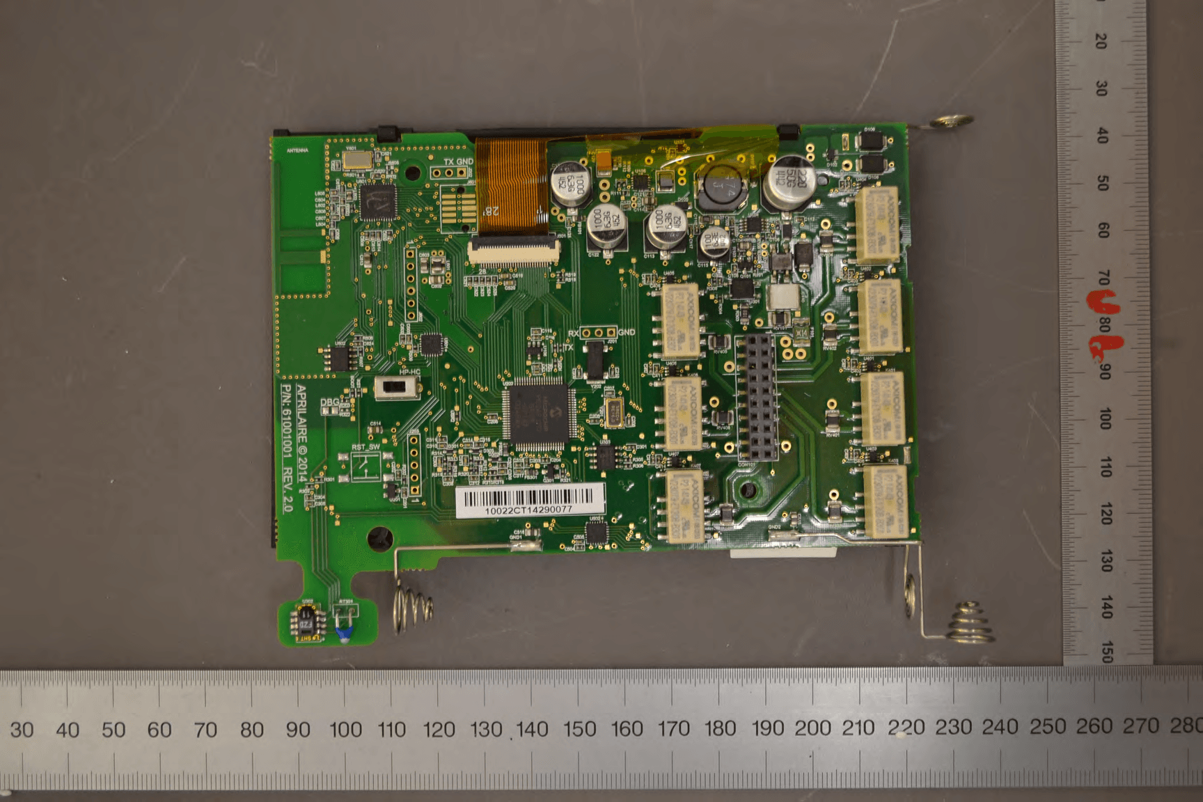
R33C4THERM
Feb 09, 2015THERMOMETER
Equipment Class
DTS - Digital Transmission System