R33LSZ1011LSZ-101-X Wireless Switch
Snap One, LLC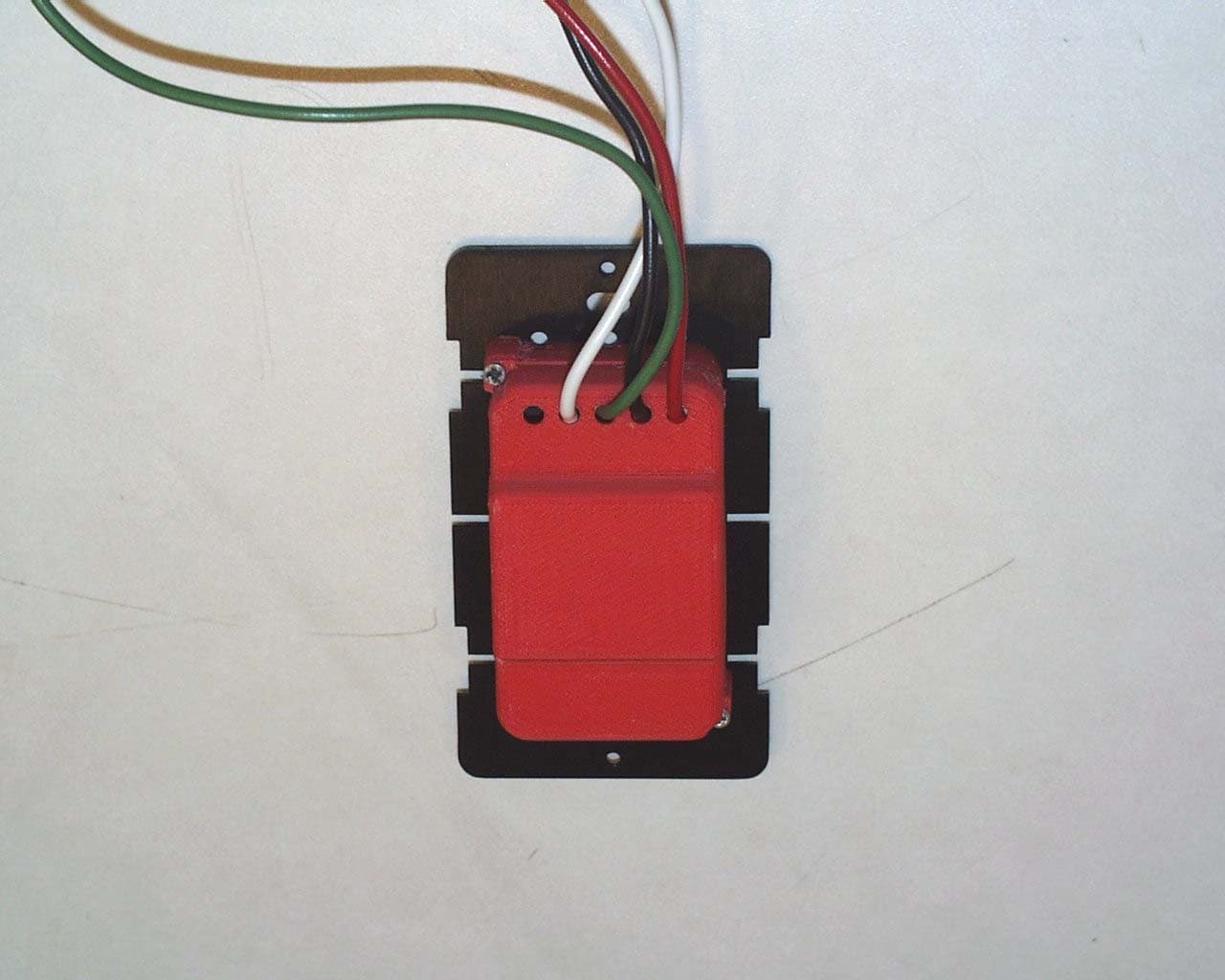
Click to zoom
Application Details
- Equipment Class
- DTS - Digital Transmission System
- Date of Grant
- Oct 28, 2004
- Application Purpose
- Original Equipment
- Date of Application
- Oct 28, 2004
- Equipment Note
- LSZ-101-X Wireless Switch
- Frequency Range
- 2400.00000000 - 2483.50000000
- Company
- Snap One, LLC
- Country
- United States
Documents & Files
Document Text
Text extracted from the exhibit documents filed with the FCC. Open a document above to read the original.
Users Manual
Wireless Switch Installation and User Guide Supported Models and Fixtures This installation and user guide covers these switch models: LSZ-101-W Wireless Switch (802.15.4) LSZ-101-B Wireless Switch (802.15.4) LSZ-101-A Wireless Switch (802.15.4) This switch can operate independently or as a device you can control with your Control4 ® system. The switch installs in a standard wall box using typical wiring standards and it communicates to the Control4 system using a wireless connection. The switch supports: •120 Volt incandescent (all types) •120 Volt halogen (all types) •120 Volt magnetic low voltage (all types with 70 percent or greater load factor) Installation Instructions 1 Ensure that the location and intended use meet the following criteria: • Install in accordance with all national and local electrical codes. • Wall box size required depends on your wiring. To calculate the total depth required, add 2.5 inches to the amount of space recommended in the NEC (National Electric Code) for your configuration. • The range and performance of the wireless control system is highly dependent on the following:(1) Distance between devices; (2) Layout of the home; (3) Walls separating devices; and (4) Electrical equipment located near devices. • If installing a dimmer in a multi-unit installation, DO NOT continue until you have read the “Multi-Unit Installations” section. • DO NOT use where total wattage of the load is under 25 watts. • DO NOT exceed maximum load rating of dimmer (which is 1000W for a single unit, if both side tabs are intact). 2 To avoid injury or death, turn OFF local electrical power. To turn off the power, either switch off the circuit breaker or remove the fuse from fuse box. To ensure the wires do NOT have power running to them, use an inductive voltage detector. 3 Use screwdriver to remove wall plate and existing switch from wall. 4 Detach existing switch or dimmer. The existing switch or dimmer is wired in one of three ways: terminal screws, backwire, or wire nuts. 5 Identify the wires in your wall box. Straighten the wire ends. With a wire cutter, cut off the bare wire just below the insulation on all wires. Use a wire stripper to strip off the installation leaving about 3/8-inch of bare wire (as shown). 6 Connect the switch wires to the wall box wires using wire nuts. Wall box wires can differ depending upon how the box was wired by your electrician and where the power source comes from—either the light fixture or the wall box. Refer to the “Sample Wiring Configurations” section. 7 Fit wires back into the wall box. Bend the wires in a zigzag pattern so that they easily fold into the wall box. 8 If you are using a Decora-style screw-on wall plate: a.Remove the switch’s black plastic sub-plate (located directly behind the screws) and store it for future use (in case you later change wall plates). b.Align the dimmer to the wall box and fasten with screws. c.Fasten the wall plate to the dimmer with screws. 9 If you are using the Control4 snap-on wall plate that shipped with your switch: a.Align the switch to the wall box and fasten it with screws b.Snap the wall plate onto the dimmer. 10 Turn ON power at the circuit breaker or replace fuse from fuse box. 11 Test the switch to see if it is working properly. See “Operation and Configuration” for specific instructions. Troubleshooting If light does not turn on: •Ensure light bulb is not burned out. •Ensure light bulb is screwed in tightly. •Ensure circuit breaker is not turned OFF or tripped. •Check for proper wiring (see the “Sample Wiring Configurations” section). Limited 1-Year Warranty This device has a limited one (1) year warranty on parts from the date of purchase. Control4 will replace or repair any defective unit. Return unit to the place of purchase for replacement. For any damages incurred, the warranty will never exceed the purchase price of the device. This warranty does not cover installation, removal, or reinstallation cost. The warranty is not valid in cases where damage incurred due to misuse, abuse, incorrect repair, or improper wiring or installation. It does not cover incidental or consequential damage. This warranty gives you specific legal rights, and you might also be entitled to other rights that vary from state to state. Some states do not allow limitations on how long an implied warranty lasts or the exclusion or limitation of incidental or conseqential damages. In these cases, the above mentioned limitations might not apply to you. For complete warranty information, see www.Control4.com.To automatically receive notification of upgrades, return the enclosed registration card or register online at www.Control4.com. Multi-Unit Installations Multi-unit installations allow you to install one stand-alone switch next to another in the same wall box. Remove Inner-Side Breakaway Tabs When doing a multi-unit installation, you must remove ONLY the breakaway tabs on the one switch side that will be adjacent to another switch side (otherwise the tabs on the 2 sides will collide). DO NOT remove tabs on any side that will become the outer side of a group of switches. Use pliers to bend a tab back and forth until it comes off. Resulting Capacity Depends on Side Tab Status •With both sides’ breakaway tabs intact, the capacity is 1000W maximum. •If you remove 1 side’s tabs, the capacity is reduced to 800W maximum. •If you remove 2 sides’ tabs, the capacity is reduced to 600W maximum. FCC and UL Information FCC ID: R33LSZ1011 This device complies with Part 15 of the FCC Rules. Operation is subject to the following two conditions: (1) this device may not cause harmful interfence, and (2) this device must accept any interference received, including interference that may cause undesired operation. UL Control number: xxxx Control4 Technical Support For help on the installation or operation of this product, email or call the Control4 Technical Support Center. Please provide your exact model number. Contact support@control4…
Text truncated - open the document above for the full version.
Cover Letter(s)
Exhibit 13 11734 South Election Drive Suite 200 Draper, Utah 84020 (801) 523-3100 To: Federal Communications Commission Date: 4/29/04 445 12 th Street, SW Washington, DC 20554 Re: Non disclosure Request for FCC ID: R33LSZ1011 We are requesting that the following documents be held and treated as confidential and proprietary information. These materials contain technical trade secret information and should be guarded from competitors as stated under the Code of Federal Regulations Title 47 Section 0.459 (3), (4) and (5). 1) Schematic 2) Block Diagrams 3) Operational Description James K. Russell Senior Electrical Engineer Control4 Technologies
External Photos
Page 1 of 2 Exhibit 3 (External Photographs) Photograph 1 – Front View of the EUT Page 2 of 2 Photograph 2 – Back View of the EUT
RF Exposure Info
1 MPE Calculations R33LSZ1011 2 1.0 SCOPE_________________________________________________________3 2.0 REVISION LEVEL_______________________________________________4 3.0 REFERENCE DOCUMENTS______________________________________4 4.0 CALCULATIONS________________________________________________5 5.0 CONCLUSION___________________________________________________6 3 1.0 SCOPE: This Report Demonstrates Evaluation and Compliance for Human Exposure to Radiofrequency Electromagnetic Fields as Outlined by the Federal Communications Commission Office of Engineering and Technology Bulletin 65. 2.0 REVISION LEVEL: DATE COMMENTS REVISION 10/25/2004 Created. 1.0 3.0 REFERANCE DOCUMENTS: (A) Limits for Maximum Permissible Exposure (MPE). Code of Federal Regulations Title 47, Volume 1, Section 1.1310. (B) Evaluating Compliance with FCC Guidelines for Human Exposure to Radiofrequency Electromagnetic Fields. OET Bulletin 67 Edition 97-01. 4.0 CALCULATIONS: The following worst case emissions are based on a PPt (Peak Power Total) measurement of 10.4 dBm. And the worst case antenna gain on axis is found to be 3.64 dBi. Total radiated power at the Transmitter: A) Pt = 10.4 dBm + 3.64 dBi = 14.4 EIRP 14.04 EIRP = 25.35 mW or .02535 Watts. Power density at a distance of .02 meters is: B) S = EIRP/4π·R^2 S = Power density (mW/cm^2) EIRP = Equivalent isotropically radiated power (mW) R = Distance to the center of radiation of the antenna (cm) 4 S = 100.869 mW per meter squared. Power density based on a Per Centimeter Squared is: 10.08 μW per centimeter squared. 5.0 CONCLUSION: Based on the FCC Limits for Maximum Permissible Exposure (MPE) given in Table 1 of reference document (A) this device falls under the required limits.
Test Report
Exhibit 6 TEST REPORT FROM: COMMUNICATION CERTIFICATION LABORATORY TEST OF: LSZ-101-x FCC ID: R33LSZ1011 To FCC PART 15, Subpart C (15.203, 15.207, 15.247) Test Report Serial No: 73-7960 TEST REPORT FROM: COMMUNICATION CERTIFICATION LABORATORY 1940 W. Alexander Street Salt Lake City, Utah 84119-2039 Type of Report: Certification TEST OF: LSZ-101-x FCC ID: R33LSZ1011 To FCC PART 15, Subpart C (15.203, 15.207, 15.247) Test Report Serial No: 73-7960 Applicant: Control4 11734 S. Election Drive, Suite 200 Draper, UT 84020 Date of Test: April 26, 2004 Issue Date: May 3, 2004 Equipment Receipt Date: April 25, 2004 COMMUNICATION CERTIFICATION LABORATORY TEST REPORT: 73-7960 FCC ID#: R33LSZ1011 Page 2 of 52 CERTIFICATION OF ENGINEERING REPORT This report has been prepared by Communication Certification Laboratory to document compliance of the device described below with the requirements of Federal Communications Commission (FCC) Part 15, Subpart C, Sections 15.203, 15.207, and 15.247. This report may be reproduced in full, partial reproduction may only be made with the written consent of the laboratory. The results in this report apply only to the sample tested. - Applicant: Control4 - Manufacturer: Control4 - Brand Name: Control4 - Model Number: LSZ-101-x - FCC ID Number: R33LSZ1011 On this 3 rd day of May 2004, I, individually, and for Communication Certification Laboratory, certify that the statements made in this engineering report are true, complete, and correct to the best of my knowledge, and are made in good faith. Although NVLAP has recognized that the Communication Certification Laboratory EMC testing facilities are in good standing, this report must not be used to claim product certification, approval, or endorsement by NVLAP, NIST, or any agency of the federal government. COMMUNICATION CERTIFICATION LABORATORY Tested by: Norman P. Hansen EMC Technician COMMUNICATION CERTIFICATION LABORATORY TEST REPORT: 73-7960 FCC ID#: R33LSZ1011 Page 3 of 52 TABLE OF CONTENTS PAGE SECTION 1.0 CLIENT INFORMATION .................................4 SECTION 2.0 EQUIPMENT UNDER TEST (EUT) ..........................5 SECTION 3.0 TEST SPECIFICATION, METHODS & PROCEDURES ...........8 SECTION 4.0 OPERATION OF EUT DURING TESTING ...................14 SECTION 5.0 SUMMARY OF TEST RESULTS ...........................16 SECTION 6.0 MEASUREMENTS, EXAMINATIONS AND DERIVED RESULTS .....17 APPENDIX 1 TEST PROCEDURES AND TEST EQUIPMENT ..................34 APPENDIX 2 PHOTOGRAPHS .........................................43 COMMUNICATION CERTIFICATION LABORATORY TEST REPORT: 73-7960 FCC ID#: R33LSZ1011 Page 4 of 52 SECTION 1.0 CLIENT INFORMATION 1.1 Applicant: Company Name: Control4 11734 S. Election Drive, Suite 200 Draper, UT 84020 Contact Name: James Russell Title: Senior Design Engineer 1.2 Manufacturer: Company Name: Control4 11734 S. Election Drive, Suite 200 Draper, UT 84020 Contact Name: James Russell Title: Senior Design Engineer COMMUNICATION CERTIFICATION LABORATORY TEST REPORT: 73-7960 FCC ID#: R33LSZ1011 Page 5 of 52 SECTION 2.0 EQUIPMENT UNDER TEST (EUT) 2.1 Identification of EUT: Brand Name: Control4 Model Name or Number: LSZ-101-x Serial Number: None Options Fitted: N/A Country of Manufacture: U.S.A. 2.2 Description of EUT: The LSZ-101-x is a solid state wireless network able wall box decora™ style Switch. It is designed to handle up to 1000 watts. The LSZ-101-x replaces standard mechanical On/Off switches using conventional electrical residential wiring. It fits into all standard plastic or metal electrical wall box sizes. The LSZ- 101-x is fully programmable . The LSZ-101-x is network able via a standard 2.4 GHz 802.15.4 low power RF transceiver enabling a full range of system control functions including Lighting Scene Control, Security Lighting, Automatic Shut Off, Scheduled Events and more. The 802.15.4 transceiver uses 15 channels in the 2400 to 2483.5 MHz band. The individual channels are shown in the following plots. dBm 10 0 -10 -20 -30 -40 -50 -60 -70 -80 -90 Control4 Zigbee radio frequencies Trace A Start: 2.402500 GHzStop: 2.427500 GHz Res BW: 100 kHzVid BW: 300 kHzSweep: 20 ms 04/26/2004 2:48:40 PMHP8566BLCHANS.SPT Lower channels 1 1 2.405375 GHz 5.8000 dBm 2 2 2.409825 GHz 5.2000 dBm 3 3 2.414875 GHz 5.3000 dBm 4 4 2.420525 GHz 4.6000 dBm 5 5 2.425650 GHz 4.6000 dBm COMMUNICATION CERTIFICATION LABORATORY TEST REPORT: 73-7960 FCC ID#: R33LSZ1011 Page 6 of 52 dBm 10 0 -10 -20 -30 -40 -50 -60 -70 -80 -90 Control4 Zigbee Radio Frequencies Trace A Start: 2.427500 GHzStop: 2.452500 GHz Res BW: 100 kHzVid BW: 300 kHzSweep: 20 ms 04/26/2004 2:54:11 PMHP8566B Middle channels 1 1 2.429800 GHz 4.7000 dBm 2 2 2.434900 GHz 4.2000 dBm 3 3 2.440000 GHz 5.2000 dBm 4 4 2.445050 GHz 3.8000 dBm 5 5 2.450175 GHz 5.2000 dBm dBm 10 0 -10 -20 -30 -40 -50 -60 -70 -80 -90 Control4 Zigbee Radio Frequencies Trace A Start: 2.452500 GHzStop: 2.477500 GHz Res BW: 100 kHzVid BW: 300 kHzSweep: 20 ms 04/26/2004 2:59:12 PMHP8566B Upper channels 1 1 2.454850 GHz 3.9000 dBm 2 2 2.460175 GHz 3.4000 dBm 3 3 2.465100 GHz 3.7000 dBm 4 4 2.470750 GHz 3.7000 dBm 5 5 2.475800 GHz 3.1000 dBm COMMUNICATION CERTIFICATION LABORATORY TEST REPORT: 73-7960 FCC ID#: R33LSZ1011 Page 7 of 52 2.3 EUT and Support Equipment: The FCC ID numbers for all the EUT and support equipment used during the test (including inserted cards) are listed below: Brand Name Model Number Serial No. FCC ID Number Description Name of Interface Ports / Interface Cables BN: Control4 MN: LSZ-101-x (1) R33LSZ1011 Residential Electrical Switch See Section 2.4 Note: (1) EUT. The support equipment listed above was not modified in order to achieve compliance with this standard. 2.4 Interface Ports on EUT: Name of Ports No. of Ports Fitted to EUT Cable Descriptions/Length AC power 1 3 conductor power cord/6 feet Load 1 Single conductor/3 ½ feet 2.5 Modification Incorporated/Special Accessories on EUT: There were no modifications or special accessories required to comply with t…
Text truncated - open the document above for the full version.
Test Setup Photos
Page 1 of 4 Exhibit 7 (Setup Photographs) Photograph 1 – Front View Radiated Disturbance Worst Case Configuration Page 2 of 4 Photograph 2 – Back View Radiated Disturbance Worst Case Configuration Page 3 of 4 Photograph 3 – Front View Conducted Disturbance Worst Case Configuration Page 4 of 4 Photograph 4 – Back View Conducted Disturbance Worst Case Configuration
Contact Information
Applicant
Roger J Midgley(Principle Compliance Engineer)
Test Firm
Nemko-CCL, Inc.Thomas Jackson
Technical Specifications
| # | Rule Parts | Frequency Range | Power Output |
|---|---|---|---|
| 1 | 15C | 2.40 GHz - 2.48 GHz | 10.47 mW |
Other Applications from Snap One, LLC
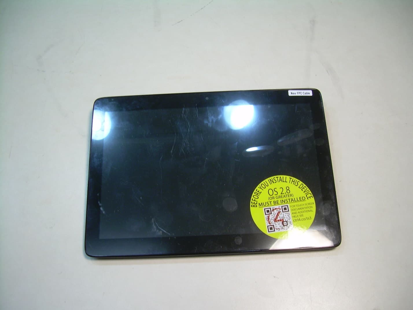
R33C4TT10
Jan 26, 2016Touchscreen Display for home automation system
Equipment Class
DTS - Digital Transmission System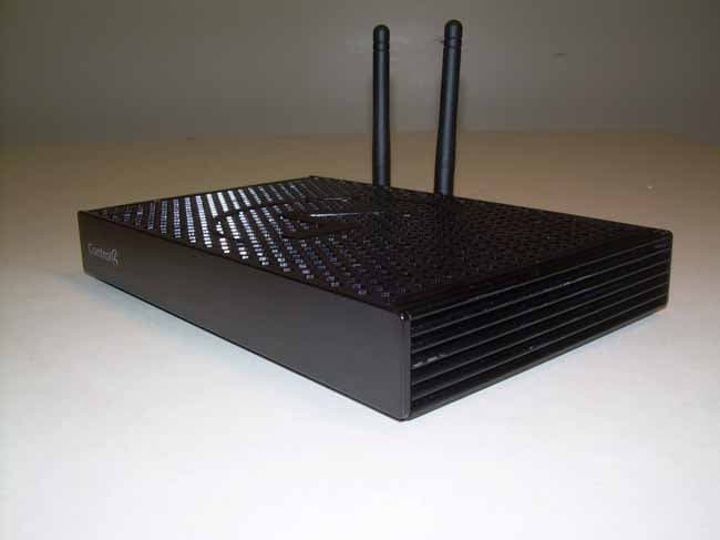
R33C4EA1
Jan 25, 2016Controller for home automation system
Equipment Class
DTS - Digital Transmission System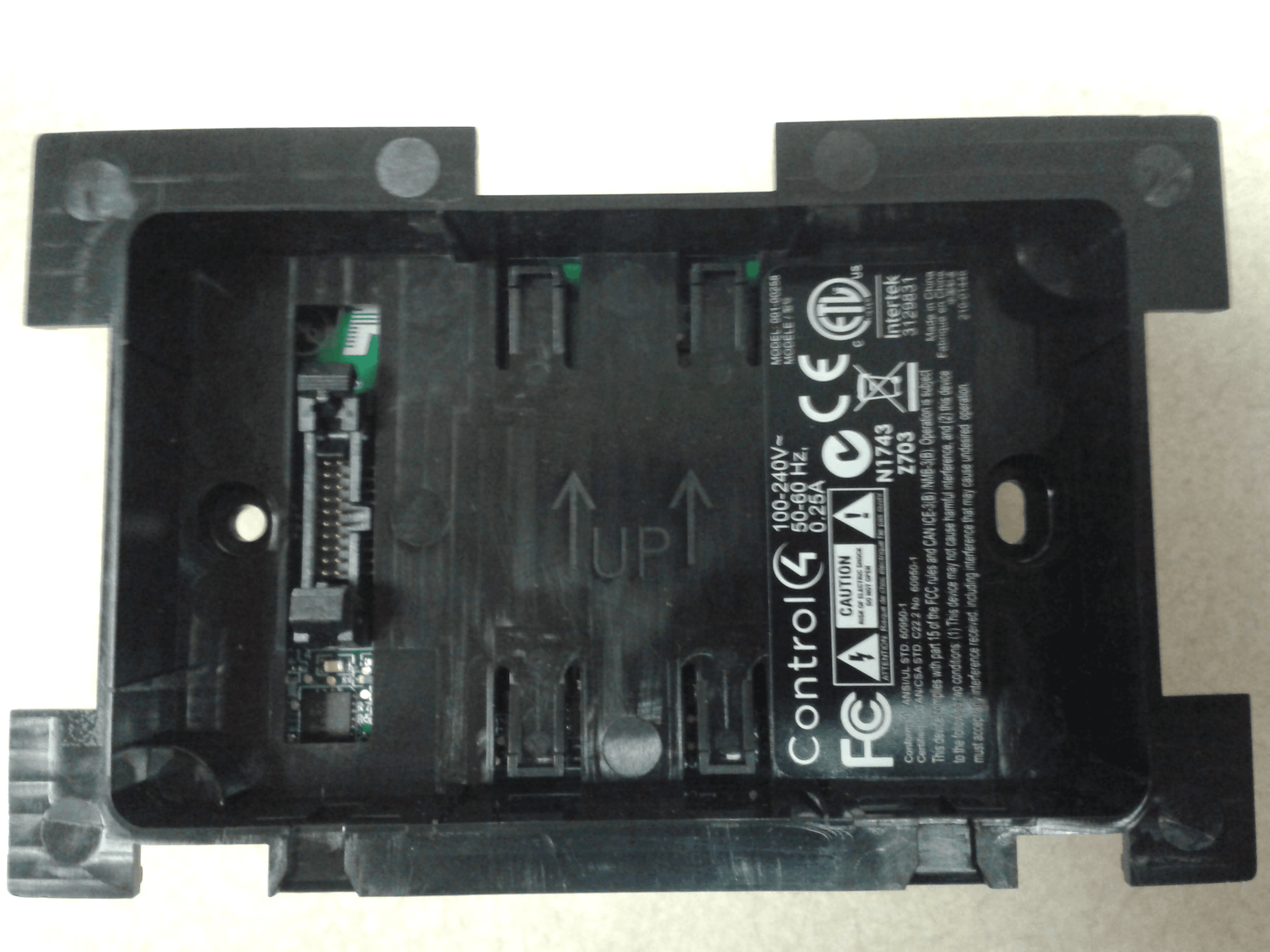
R33C4LGWM
Mar 24, 2015WIFI MODULE
Equipment Class
DTS - Digital Transmission System
R33C4SR260
Mar 18, 2015Remote control
Equipment Class
DTS - Digital Transmission System
R33C4THERM
Feb 09, 2015THERMOMETER
Equipment Class
DTS - Digital Transmission System