R33TSX38C21WiFi Mini/Touch Screen
Snap One, LLC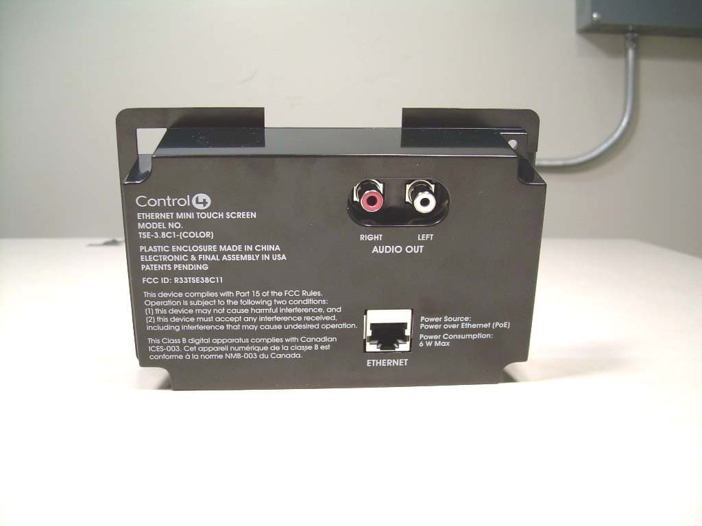
Click to zoom
Application Details
- Equipment Class
- DTS - Digital Transmission System
- Date of Grant
- Feb 28, 2007
- Application Purpose
- Original Equipment
- Date of Application
- Feb 28, 2007
- Equipment Note
- WiFi Mini/Touch Screen
- Frequency Range
- 2405.40000000 - 2476.60000000
- Company
- Snap One, LLC
- Country
- United States
Documents & Files
Document Text
Text extracted from the exhibit documents filed with the FCC. Open a document above to read the original.
Users Manual
Mini Touch Screen Installation Guide Supported ModelsWhat’s in the BoxCarefully unpack the contents from the box and make sure the following items are included in the box. If any item is missing or damaged, please contact your Control4-authorized reseller immediately. • Control4 Mini Touch Screen • Mini Touch Screen Installation Guide (this document) • Two sheet metal screws (1/2 inch) for attachment to a plastic wall box. (Metal wall boxes require machine screws. They are included with the the metal wall box kit.) Graphical Symbols in this GuideThe following symbols and their description s draw your attention to important safe practices and additional information that can help you avoid injury, death, or loss of material or time. WARNING! This indicates a potentially hazardous situation that, if not avoided, may result in death or injury. DO NOT IGNORE A WARNING! IMPORTANT! This indicates information that will help you avoid damage to your equipment, loss of materials, or loss of time. PAY ATTENTION TO THESE IMPORTANT STATEMENTS! NOTE: This indicates a note on related information about the current topic. TIP: This indicates a tip that might save you time or effort. Important Safety Instructions1. Read these instructions. 2. Keep these instructions. 3. Heed all warnings. 4. Follow all instructions. 5. Do not use this apparatus near water. 6. Clean only with dry cloth. 7. Install in accordance with the manufacturer’s instructions. 8. Do not install near any heat sources such as radiators, heat registers, stoves, or other apparatus (including amplifiers) that produce heat. 9. Protect the power cords, if applicable, from being walked on or pinched particularly at plugs, convenience receptacles, and the poi nt where they exit from the apparatus. 10. Only use attachments/accessories specified by the manufacturer.11. If applicable, unplug this a pparatus duri ng lightning storms or when unused for long periods of time. 12. Refer all servicing to qualified service personnel. Servicing is required when the apparatus has been dam aged in any way, such as power-supply cord or plug is damaged, liquid has been spilled or objects have fallen into the appara-tus, the apparatus has been exposed to rain or moisture, does not operate normally, or has been dropped. WARNING! To reduce the risk of fire or el ectrical shock, do not expose this apparatus to rain or moisture. WARNING! To avoid bodily harm, always contact a Control4-authorized reseller for assistance if any repair or adjustment is required. WARNING! Do not place unit near sources of heat or expose to direct sunlight for an extended period of time. IMPORTANT! Do not use pens or sharp objects to navigate or make selections on the screen. To select an item or scroll through a list, use either your fingertip or the Select Dial. IMPORTANT! Improper use or installation can cause LOSS/DAMAGE OF PROPERTY. Placement and Model OptionsThe Control4 Mini Touch Screen offers complete system control in an elegant and compact design. The Mini Touch Sc reen is equipped with the touch screen, an intuitive Select Dial, and a unique programmable shortcut button. PlacementPlace the Mini Touch Screen in a convenien t location at eye level, typically near the entrace of the room, approximately 57 to 61 inches from the floor. The model used also influences placemen t. The Mini Touch Screen comes in two models: Ethernet and WiFi. These options are described in the next two sections. Option 1: Ethernet ModelThe Ethernet Mini Touch Screen require s a Power over Ethernet (PoE) device that injects electrical current into the Ethernet cable in order to provide the Ethernet Mini Touch Screen with both power and a network connection. See Figure 1. The Ethernet Mini Touch Screen works with the Control4 Power Over Ethernet Injector (model # AC-POE1-B) or a third-party PoE injector or switch. If you plan to use a third-party Po E solution or a non-standard connection cable, refer to “Power Interface Requirements” (back page) for the specifications. Ethernet Placement: Place the PoE Injector near your gateway/router/switch. Pull the Ethernet cable from that location to the location of where you want to place your Mini Touch Screen. FIGURE 1. Ethernet Model - Requires Ethernet Wiring to Mini Touch Screen. Option 2: WiFi Model The WiFi Mini Touch Screen differs fr om the Ethernet model in two ways: • It uses a WiFi antenna that communicates via WiFi to a Wireless Access Point. • It gets its power from an AC power source close to the Mini Touch Screen. This power connection r equires both neutral and hot connec- tions. See Figure 2. WiFi Placement: Place the WiFi Model above a power source, such as at an outlet. Ensure you have WiFi in the home. FIGURE 2. WiFi Model - Requires AC power to Mini Touch Screen. Wall Box Kit OptionsThere are four wall box options to in stall the Mini Touch Screen. Metal and plastic wall boxes are ava ilable for new or retrofit versions. The following diagrams show the available wall mounting kits. FIGURE 3. Mini Touch Screen/LCD Keypad Wall Box Kits - New Construction FIGURE 4. Mini Touch Screen/LCD Keypad Wall Box Kit - Retrofit (includes wall box template) RequirementsTo install the Mini Touch Screen, you need the following: • Home Theater Controller or Media Controller fully installed and config-ured with a Control4 system. • (Optional) An amplifier or amplified speakers. • (Optional) Any RCA cables required to connect the Mini Touch Screen and the amplifier or amplified speakers. • Ethernet model: • Ethernet network installed and available that includes a gateway/ router/switch. • Control4 PoE Injector (model #AC-POE1-B) or another third-party PoE injector or switch. • Two Ethernet Category 5 cables to support your PoE injector: (1) one that will run from the Ethernet gateway/router/switch to the PoE injector/switch and (2) one that will run from the PoE injector/switch to the Ethernet Mini Touch Screen wall box. • WiFi model: • Wireless network (WiF…
Text truncated - open the document above for the full version.
Cover Letter(s)
11734 South Election Road Suite 200 Draper, Utah 84020 (801) 523-3100 To: Federal Communications Commission Date: 2/19/2007 445 12 th Street, SW Washington, DC 20554 Re: Non disclosure Request for FCC ID: R33TSX38C21 We are requesting that the following documents be held and treated as confidential and proprietary information. These materials contain technical trade secret information and should be guarded from competitors as stated under the Code of Federal Regulations Title 47 Section 0.459 (3), (4) and (5). 1) Schematic 2) Block Diagrams 3) Operational Description Joseph S. Collier Hardware Engineer Control4 Technologies
External Photos
Front View of the TSE-3.8C2-x Back View of the TSE-3.8C2-x
Internal Photos
Front View of the TSG-3.8C2-x Back View of the TSG-3.8C2-x PCB Front Side of the TSG-3.8C2-x PCB Front Side of the TSE-3.8C2-x PCB Photograph 11 – Back Side of the TSE-3.8C2-x PCB
RF Exposure Info
1 MPE Calculations R33TSX38C21 2 1.0 SCOPE_________________________________________________________3 2.0 REVISION LEVEL_______________________________________________4 3.0 REFERENCE DOCUMENTS______________________________________4 4.0 CALCULATIONS________________________________________________5 5.0 CONCLUSION___________________________________________________6 3 1.0 SCOPE: This Report Demonstrates Evaluation and Compliance for Human Exposure to Electromagnetic Fields as Outlined by the Federal Communications Commission Office of Engineering and Technology Bulletin 65. 2.0 REVISION LEVEL: DATE COMMENTS REVISION 2/19/2007 Created. 1.0 3.0 REFERANCE DOCUMENTS: (A) Limits for Maximum Permissible Exposure (MPE). Code of Federal Regulations Title 47, Volume 1, Sections 1.1310 (B) Limits for Maximum Permissible Exposure (MPE). Code of Federal Regulations Title 47, Volume 1, Sections 2.1093 (C) Evaluating Compliance with FCC Guidelines for Human Exposure to Radiofrequency Electromagnetic Fields. OET Bulletin 67 Edition 97-01. 4.0 CALCULATIONS: The following worst case emissions are based on a PPt (Peak Power Total) measurement of 10.40 dBm into the antenna. And the worst case antenna gain on axis is found to be 0.0 dBi. Total power into antenna: A) Pt = 10.40 dBm = 10^(10.40 dBm/10) = 10.96 mW Total effective isotropic radiated power at the Transmitter: B) EIRP = 10.40 dBm + 0.0dBi = 10.4 dBm 10.4 dBm = 11.0 mW Power density at a distance of 20 centimeters is: 4 C) 2 Rπ4 EIRP =S = 2.2 μW/cm 2 Where S = Power density (mW/cm^2), EIRP = Equivalent isotropic radiated power (mW), R = Distance to the center of radiation of the antenna (cm) 5.0 CONCLUSION: Based on the FCC Limits for Maximum Permissible Exposure (MPE) given in Table 1 of reference document (A) as 1 mW/cm 2 this device falls under the required limits.
Test Report
COMMUNICATION CERTIFICATION LABORATORY 1940 West Alexander Street Salt Lake City, UT 84119 801-972-6146 Test Report Certification Test Of: TSE-3.8C2-x and TSG-3.8C2-x FCC ID: R33TSX38C21 Test Specifications: FCC PART 15, Subpart C (15.203, 15.207, 15.247) Test Report Serial No: 73-8438 Applicant: Control4 11734 S. Election Drive, Suite 200 Draper, UT 84020 Dates of Test: November 21 and 28, 2006 Issue Date: December 4, 2006 Accredited Testing Laboratory By: NVLAP Lab Code 100272-0 COMMUNICATION CERTIFICATION LABORATORY TEST REPORT: 73-8438 FCC ID#: R33TSX38C21 Page 2 of 54 CERTIFICATION OF ENGINEERING REPORT This report has been prepared by Communication Certification Laboratory to document compliance of the device described below with the requirements of Federal Communications Commission (FCC) Part 15, Subpart C, Sections 15.203, 15.207, and 15.247. This report may be reproduced in full, partial reproduction may only be made with the written consent of the laboratory. The results in this report apply only to the sample tested. - Applicant: Control4 - Manufacturer: Control4 - Brand Name: Control4 - Model Number: TSE-3.8C2-x and TSG-3.8C2-x - FCC ID Number: R33TSX38C21 On this 4 th day of December 2006, I, individually, and for Communication Certification Laboratory, certify that the statements made in this engineering report are true, complete, and correct to the best of my knowledge, and are made in good faith. Although NVLAP has recognized that the Communication Certification Laboratory EMC testing facilities are in good standing, this report must not be used to claim product certification, approval, or endorsement by NVLAP, NIST, or any agency of the federal government. COMMUNICATION CERTIFICATION LABORATORY Tested by: Norman P. Hansen EMC Technician COMMUNICATION CERTIFICATION LABORATORY TEST REPORT: 73-8438 FCC ID#: R33TSX38C21 Page 3 of 54 TABLE OF CONTENTS PAGE SECTION 1.0 CLIENT INFORMATION.................................4 SECTION 2.0 EQUIPMENT UNDER TEST (EUT) ..........................5 SECTION 3.0 TEST SPECIFICATION, METHODS & PROCEDURES ...........8 SECTION 4.0 OPERATION OF EUT DURING TESTING ...................15 SECTION 5.0 SUMMARY OF TEST RESULTS...........................17 SECTION 6.0 MEASUREMENTS, EXAMINATIONS AND DERIVED RESULTS.....18 APPENDIX 1 TEST PROCEDURES AND TEST EQUIPMENT ..................33 APPENDIX 2 PHOTOGRAPHS.........................................42 COMMUNICATION CERTIFICATION LABORATORY TEST REPORT: 73-8438 FCC ID#: R33TSX38C21 Page 4 of 54 SECTION 1.0 CLIENT INFORMATION 1.1 Applicant: Company Name: Control4 11734 S. Election Drive, Suite 200 Draper, UT 84020 Contact Name: Joseph Collier Title: Engineer 1.2 Manufacturer: Company Name: Control4 11734 S. Election Drive, Suite 200 Draper, UT 84020 Contact Name: Joseph Collier Title: Engineer COMMUNICATION CERTIFICATION LABORATORY TEST REPORT: 73-8438 FCC ID#: R33TSX38C21 Page 5 of 54 SECTION 2.0 EQUIPMENT UNDER TEST (EUT) 2.1 Identification of EUT: Brand Name: Control4 Model Name or Number: TSE-3.8C2-x and TSG-3.8C2-x Serial Number: None Options Fitted: N/A 2.2 Description of EUT: The TSE-3.8C2-x is a color touch panel and a remote audio server packed into a four-inch touch screen. An 802.15.4 Zigbee radio is used for remote programming and control. Power is provided from a Power-Over-Ethernet adapter that supplies 48 VDC to the Ethernet port of the TSE-3.8C2-x. For this testing, an I.T.E. PW130 power supply was used to power the EUT. The TSG-3.8C2-x is an AC powered version of the TSE-3.8C2-x and has no Ethernet connection. Communication is via the Zigbee radio or by an 802.11g modular transceiver in the internal USB port of the TSG-3.8C2-x. The Edimax 802.11g transceiver module has been granted modular approval for the FCC using FCC Identification Number NDD9573170512. The “x” in the model number is used to indicate the color of the plastic faceplates of the TSG-3.8C2-x and TSE-3.8C2-x. Both the TSE-3.8C2-x and TSG-3.8C2-x use the same PCB only the circuitry is populated differently in the power supply section to allow connection of the appropriate power source. Both units were tested and the worst-case emissions found during testing are shown in this report. The 802.15.4 transceiver uses 15 channels in the 2400 to 2483.5 MHz band. The individual channels are shown in the following table. Channel # Frequency (MHz) Channel # Frequency (MHz) Channel # Frequency (MHz) 0 2405.4 5 2430.7 A 2456.1 1 2410.5 6 2435.7 B 2461.2 2 2415.5 7 2440.7 C 2466.4 3 2420.6 8 2445.9 D 2471.4 4 2425.6 9 2451.1 E 2476.6 This report covers the 802.15.4 ZigBee transceiver and testing was performed to FCC Part 15 Subpart C. The digital and COMMUNICATION CERTIFICATION LABORATORY TEST REPORT: 73-8438 FCC ID#: R33TSX38C21 Page 6 of 54 control circuitry testing is to be covered in a separate report. The Edimax 802.11g module carries its own modular certification and was not addressed in this testing and report. 2.3 EUT and Support Equipment: The FCC ID numbers for all the EUT and support equipment used during the test (including inserted cards) are listed below: Brand Name Model Number Serial No. FCC ID Number Description Name of Interface Ports / Interface Cables BN: Control4 MN: TSE-3.8C2-x (Note 1) R33TSX38C21 Touch Screen Panel See Section 2.4 BN: Control4 MN: TSG-3.8C2-x (Note 1) R33TSX38C21 Touch Screen Panel See Section 2.4 BN: Ault MN:PW130 None Power-over- Ethernet Injector LAN/Cat5 cable LAN w/power/Cat5 cable (Note 2) BN: TRENDnet MN: TE100-S8P SN: 0243C3A16540 DoC 8 port LAN hub Ethernet/Cat 5 cable w/RJ45 connectors (Note 2) BN: Allied Telesyn MN: AT-MC13 DoC Copper to fiber Ethernet adapter Wired/Cat5 cable Fiber/Fiber Optic cable BN: Control4 MN: ZGateway None Zigbee transceiver USB/USB cable BN: Dell Latitude MN: D810 DoC Laptop computer LAN/Cat 5 cable Note: (1) EUT. (2) Interface port connected to EUT (See Section 2.4) The support equipment listed above was not modified in order to achieve compliance with this st…
Text truncated - open the document above for the full version.
Test Setup Photos
Front View Radiated Disturbance Worst Case Configuration Back View Radiated Disturbance Worst Case Configuration Front View Conducted Disturbance Worst Case Configuration Back View Conducted Disturbance Worst Case Configuration
Contact Information
Applicant
Roger J Midgley(Principle Compliance Engineer)
Test Firm
Nemko-CCL, IncThomas Jackson
Technical Specifications
| # | Rule Parts | Frequency Range | Power Output |
|---|---|---|---|
| 1 | 15C | 2.41 GHz - 2.48 GHz | 690.00 µW |
Other Applications from Snap One, LLC
R33C4TT10
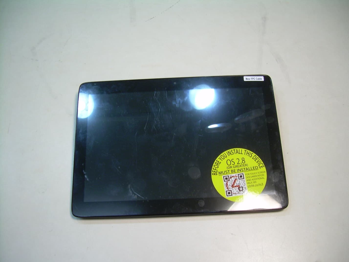
Jan 26, 2016Touchscreen Display for home automation system
Equipment Class
DTS - Digital Transmission System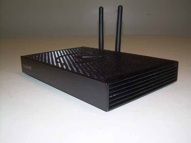
R33C4EA1
Jan 25, 2016Controller for home automation system
Equipment Class
DTS - Digital Transmission System
R33C4LGWM
Mar 24, 2015WIFI MODULE
Equipment Class
DTS - Digital Transmission System
R33C4SR260
Mar 18, 2015Remote control
Equipment Class
DTS - Digital Transmission System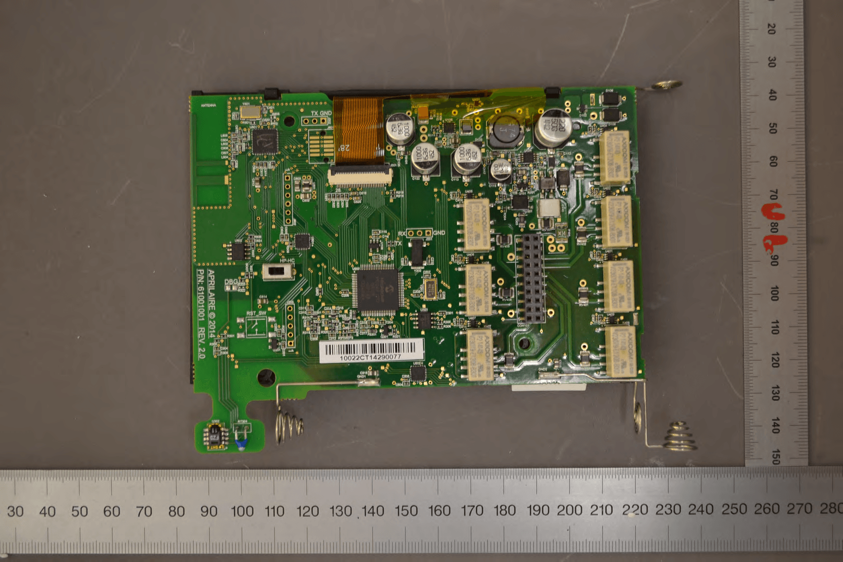
R33C4THERM
Feb 09, 2015THERMOMETER
Equipment Class
DTS - Digital Transmission System