RHHPAU01Z-Wave Dongle
Philio Technology Corporation
Click to zoom
Application Details
- Equipment Class
- DXX - Part 15 Low Power Communication Device Transmitter
- Date of Grant
- Oct 21, 2014
- Application Purpose
- Original Equipment
- Date of Application
- Oct 21, 2014
- Equipment Note
- Z-Wave Dongle
- Frequency Range
- 908.40000000 - 916.00000000
- Country
- Taiwan
Documents & Files
Document Text
Text extracted from the exhibit documents filed with the FCC. Open a document above to read the original.
Users Manual
PAU01 Z-Wave Dongle Philio Z-Wave Utility Manual Version: 2.2 Date: 2014-09-04 Table of Contents 1.Copyright and Confidential.......................................................................1 2.Disclaimer...............................................................................................1 3.Abbreviations..........................................................................................1 4.Introduction............................................................................................2 5.Installation..............................................................................................3 5.1.Install Dongle Driver.......................................................................3 5.2.Install Application...........................................................................8 6.Start.......................................................................................................8 7.Binding..................................................................................................10 7.1.Include Device..............................................................................11 7.2.Exclude Device.............................................................................13 8.Report Form..........................................................................................14 9.Z-Wave Command Function....................................................................16 9.1.How to Send Command................................................................17 10.Consistent Test....................................................................................19 11.Specification.......................................................................................21 Philio Technology Corporation - I - CONFIDENTIAL PHILIO Z-Wave Utility Manual 1.Copyright and Confidential The information contained in this document or diagram is confidential and proprietary to Philio Technology Corporation This information may not be distributed or used for any purpose other than the evaluation of Philio’s solutions, nor may it be disclosed to any party without the prior written consent from Philio. All Rights Reserved. 2.Disclaimer This document or diagram and the information contained herein is provided on an "AS IS" basis and Philio DISCLAIMS ALL WARRANTIES, EXPRESS OR IMPLIED, INCLUDING BUT NOT LIMITED TO ANY WARRANTY THAT THE USE OF THE INFORMATION HEREIN WILL NOT INFRINGE ANY RIGHTS OR ANY IMPLIED WARRANTIES OF MERCHANTABILITY OR FITNESS FOR A PARTICULAR PURPOSE. 3.Abbreviations AbbreviationExplanation NIDNetwork ID RFRadio Frequency SDKSoftware Development Kit SISSUC ID Server SUCStatic Update Controller Philio Technology Corporation Page 1 CONFIDENTIAL PHILIO Z-Wave Utility Manual 4.Introduction The “Philio Z-Wave Utility” application is a tool for Philio RD testing, and also suitable for product line testing in factory. The purpose of this manual is to help user familiar the functionality of the application, and operate the user interface. This tool is for Z-Wave product, some concept of the Z-Wave network, or the specification of the Z-Wave command, please refer to the Z-Wave SDK first. The follow subjects will describe these scopes: Installation Start Binding Report Form Z-Wave Command Function Consistent Test Philio Technology Corporation Page 2 CONFIDENTIAL PHILIO Z-Wave Utility Manual 5.Installation 5.1.Install Dongle Driver The dongle need the PC driver. Please extract the “ZW040x_USB_VCP_PC_Driver.zip”. There is a uzb.inf file. Insert the dongle to the PC, in the first time, the PC will issue the driver can't found. You can observe the Control Panel System and Security System →→ Hardware Device Manager →→ Click the “Device Manager”. Right Click the “Unknown device”. And select “Update Driver Software...” Philio Technology Corporation Page 3 CONFIDENTIAL PHILIO Z-Wave Utility Manual Click “Browse my computer for driver software”. Philio Technology Corporation Page 4 CONFIDENTIAL PHILIO Z-Wave Utility Manual Fill the driver file location. And click “Next”. Philio Technology Corporation Page 5 CONFIDENTIAL PHILIO Z-Wave Utility Manual Select “Install this driver software anyway”. Wait a while. Philio Technology Corporation Page 6 CONFIDENTIAL PHILIO Z-Wave Utility Manual Install OK. Philio Technology Corporation Page 7 CONFIDENTIAL PHILIO Z-Wave Utility Manual 5.2.Install Application Extract the “PhilioZWaveUtil.7z” to the folder whatever you want, but please don’t install on the remote disk, it may cause some error. Insert the dongle into the PC USB socket. And then execute the “PhilioZWaveUtil.exe” to start the application. Note: This tool is designed by .Net Framework, you need to install .Net Framework 4.0 before running the application. You can easily use the “Windows Update” to install that. Windows 7 already install .Net Framework in default. 6.Start Insert the USB dongle, and execute the “PhilioZWaveUtil.exe” to start the application. If the application can’t find the USB dongle, it will show the pop window, and click the OK button to close the application. Figure 1 USB dongle not found Normally, the application will read controller information from the USB dongle; you can see the progress bar is running. Philio Technology Corporation Page 8 CONFIDENTIAL PHILIO Z-Wave Utility Manual Figure 2 Reading the information of the controller After finish, it will show the basic information of the dongle. Home ID: The home ID of the controller. Node ID: The node ID of the controller. If the controller is secondary controller, this value may not be 1. Primary: Is the dongle is the primary controller? Secondary: Is the dongle is the secondary controller? SIS Exist: Is the Z-Wave network exist the SIS? SUC: Is this dongle is the SUC? SUC ID: If the SUC is exist, which node ID is. COM Port: The application is using which COM port to communicate with USB dongle. Philio Technology Corporation Page 9 CONFIDENTIAL PHILI…
Text truncated - open the document above for the full version.
External Photos
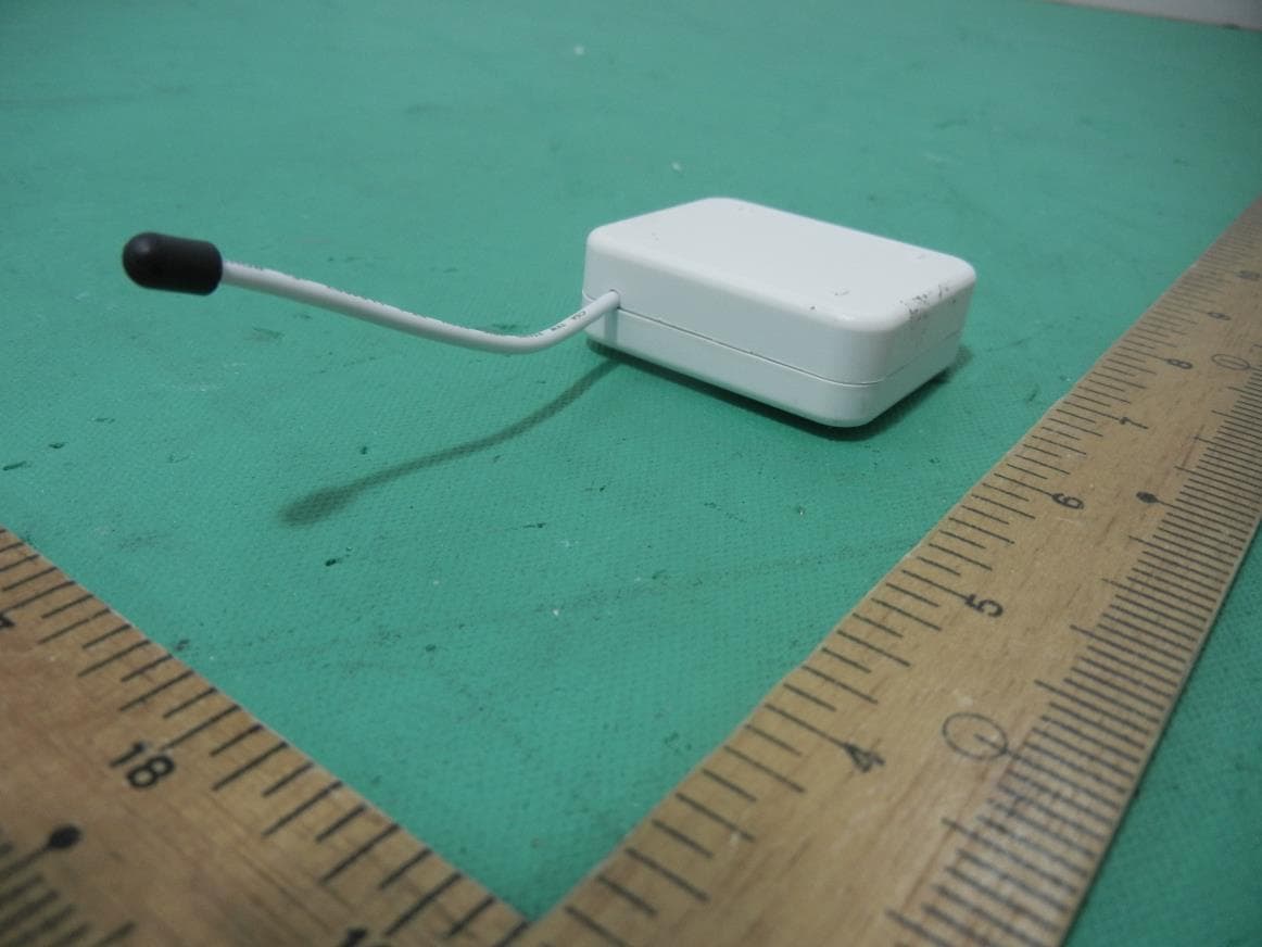
Page 1 CONSTRUCTION PHOTOS OF EUT Page 2
ID Label/Location Info
Label location 10mm 40mm
Internal Photos
Page 3 Page 4
Operational Description
FCC ID: RHHPAU01 Report No.: RF140926C11 Operational Description This device is a MZ-Wave Dongle. The transmitter of the EUT is powered by 5Vdc (host equipment). The antenna is Helical wire antenna without connector. For more detailed instruction, please take a look at the user’s manual.
Test Report
Report No.: RF140926C11 1 of 28 Report Format Version 5.0.0 FCC TEST REPORT REPORT NO.: RF140926C11 MODEL NO.: PAU01-2 (Refer to item 3.1 for more details) FCC ID: RHHPAU01 RECEIVED: Sep. 26, 2014 TESTED: Oct. 08 ~ Oct. 14, 2014 ISSUED: Oct. 15, 2014 APPLICANT: Philio Technology Corporation ADDRESS: 8F., No.653-2, Zhongzheng Rd., Xinzhuang Dist., New Taipei City 24257, Taiwan (R.O.C) ISSUED BY: Bureau Veritas Consumer Products Services (H.K.) Ltd., Taoyuan Branch LAB ADDRESS: No. 47-2, 14th Ling, Chia Pau Vil., Lin Kou Dist., New Taipei City, Taiwan, R.O.C. TEST LOCATION: No. 19, Hwa Ya 2nd Rd, Wen Hwa Tsuen, Kwei Shan Hsiang, Taoyuan Hsien 333, Taiwan, R.O.C. This report is for your exclusive use. Any copying or replication of this report to or for any other person or entity, or use of our name or trademark, is permitted only with our prior written permission. This report sets forth our findings solely with respect to the test samples identified herein. The results set forth in this report are not indicative or representative of the quality or characteristics of the lot from which a test sample was taken or any similar or identical product unless specifically and expressly noted. Our report includes all of the tests requested by you and the results thereof based upon the information that you provided to us. You have 60 days from date of issuance of this report to notify us of any material error or omission caused by our negligence, provided, however, that such notice shall be in writing and shall specifically address the issue you wish to raise. A failure to raise such issue within the prescribed time shall constitute your unqualified acceptance of the completeness of this report, the tests conducted and the correctness of the report contents. Unless specific mention, the uncertainty of measurement has been explicitly taken into account to declare the com pliance or non-compliance to the specification. This report should not be used by the client to claim product certification, approval, or endorsement by TAF or any government agencies. Report No.: RF140926C11 2 of 28 Report Format Version 5.0.0 Table of Contents RELEASE CONTROL RECORD .............................................................................................................. 3 1. CERTIFICATION ......................................................................................................................... 4 2. SUMMARY OF TEST RESULTS ................................................................................................. 5 2.1 MEASUREMENT UNCERTAINTY .............................................................................................. 5 3. GENERAL INFORMATION ......................................................................................................... 6 3.1 GENERAL DESCRIPTION OF EUT ............................................................................................ 6 3.2 DESCRIPTION OF TEST MODES .............................................................................................. 7 3.2.1 TEST MODE APPLICABILITY AND TESTED CHANNEL DETAIL ............................................. 8 3.3 DESCRIPTION OF SUPPORT UNITS ...................................................................................... 10 3.3.1 CONFIGURATION OF SYSTEM UNDER TEST ....................................................................... 10 3.4 GENERAL DESCRIPTION OF APPLIED STANDARDS ........................................................... 11 4. TEST TYPES AND RESULTS ................................................................................................... 12 4.1 RADIATED EMISSION AND BAND EDGE MEASUREMENT .................................................. 12 4.1.1 LIMITS OF RADIATED EMISSION AND BAND EDGE MEASUREMENT ............................... 12 4.1.2 TEST INSTRUMENTS .............................................................................................................. 13 4.1.3 TEST PROCEDURES ............................................................................................................... 14 4.1.4 DEVIATION FROM TEST STANDARD ..................................................................................... 14 4.1.5 TEST SETUP ............................................................................................................................ 15 4.1.6 EUT OPERATING CONDITIONS .............................................................................................. 15 4.1.7 TEST RESULTS ........................................................................................................................ 16 4.2 CONDUCTED EMISSION MEASUREMENT ............................................................................ 22 4.2.1 LIMITS OF CONDUCTED EMISSION MEASUREMENT ......................................................... 22 4.2.2 TEST INSTRUMENTS .............................................................................................................. 22 4.2.3 TEST PROCEDURES ............................................................................................................... 23 4.2.4 DEVIATION FROM TEST STANDARD ..................................................................................... 23 4.2.5 TEST SETUP ............................................................................................................................ 23 4.2.6 EUT OPERATING CONDITIONS .............................................................................................. 23 4.2.7 TEST RESULTS ........................................................................................................................ 24 5. PHOTOGRAPHS OF THE TEST CONFIGURATION ............................................................... 26 6. INFORMATION ON THE TESTING LABORATORIES .............................................................. 27 7. APPENDIX A – MODIFICATION RECORDERS FOR ENGINEERING CHANGES TO THE EUT BY THE LAB ...…
Text truncated - open the document above for the full version.
Test Setup Photos
1 PHOTOGRAPHS OF THE TEST CONFIGURATION CONDUCTED EMISSION TEST 2 RADIATED EMISSION TEST 3
Contact Information
Applicant
JAMES HUANG(CEO)
Test Firm
Bureau Veritas CPS (H.K.) Ltd., Taoyuan BranchRichard Chen
Technical Specifications
| # | Rule Parts | Frequency Range | Power Output |
|---|---|---|---|
| 1 | 15C | 908.4 MHz - 916 MHz | - |
Other Applications from Philio Technology Corporation
RHHPAB01
Nov 30, 2015Smart Energy In Wall Meter
Equipment Class
DXX - Part 15 Low Power Communication Device Transmitter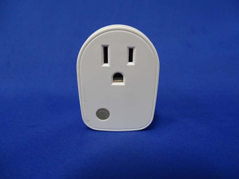
RHHPAN15
May 13, 2015Smart energy plug in switch
Equipment Class
DXX - Part 15 Low Power Communication Device Transmitter
RHHPSR04
May 05, 2015Smart Color Button
Equipment Class
DXX - Part 15 Low Power Communication Device Transmitter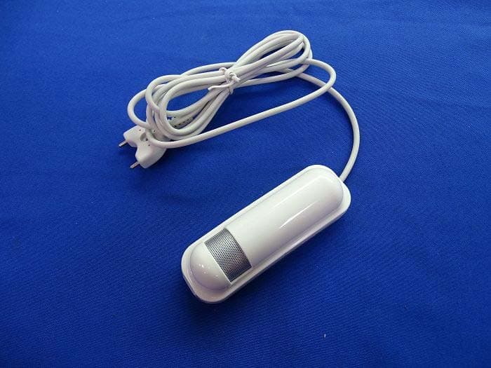
RHHPAT02
Apr 01, 2015Flood Multi Sensor
Equipment Class
DXX - Part 15 Low Power Communication Device Transmitter
RHHPSG01
Jan 27, 2015Z-Wave Smoke Sensor
Equipment Class
DXX - Part 15 Low Power Communication Device Transmitter