RIYEL2601-2Security Transmitters
Electronics Line 3000 Ltd.
Click to zoom
Application Details
- Equipment Class
- DSC - Part 15 Security/Remote Control Transmitter
- Date of Grant
- Mar 22, 2004
- Application Purpose
- Original Equipment
- Date of Application
- Mar 22, 2004
- Equipment Note
- Security Transmitters
- Frequency Range
- 418.00000000 - 418.00000000
- Company
- Electronics Line 3000 Ltd.
- Country
- Israel
Documents & Files
Document Text
Text extracted from the exhibit documents filed with the FCC. Open a document above to read the original.
Users Manual
EL-2601 The EL-2601 is a magnetic door and window contact designed for use with Electronics Line 3000’s supervised wireless range of receivers. Installation Instructions 1. To open the housing, insert a small screwdriver at the bottom of the unit between the front and back cover and twist the screwdriver to release the cover. 2. Remove the insulator separating the battery from the contacts on the battery holder. When you apply power and the Tamper switch is open, the EL-2601 enters Test mode during which a transmission is sent every few seconds. You can terminate Test mode by closing the Tamper switch. Test mode is automatically terminated after approximately five minutes. Note: Due to the occurrence of voltage delay in lithium batteries that have been in storage, the batteries may initially appear to be dead. In this case, leave the unit in Test mode for a few minutes until the battery voltage level is stabilized. 3. While the EL-2601 is in Test mode, set the receiver to Registration mode and make sure that the EL-2601’s LED lights up at least twice. After registration, close the Tamper switch to terminate Test mode. The receiver allocates a transmitter number to each registered unit. Write this number and the number of the zone on the sticker provided. Affix the sticker inside the front cover for future reference. 4. Before permanently mounting the unit, test the transmitter from the exact mounting position. If necessary, relocate the transmitter to a better position. 5. To remove the PCB, press the PCB release tab and carefully lift the board and slide the board away from the back cover. Note: When handling the PCB, do not apply pressure on the antenna. 6. If connecting a wired contact loop, remove the Wired Loop jumper (JP1). Connect the terminal block as follows: 1 – Alarm; 2 – GND. For this purpose, a wiring knockout is provided in the back cover. Note: The EL-2601 does not have EOL supervision of its loop wiring. Therefore, for UL Household Burglary installations, the loop wiring may not exceed 3 feet (0.9m). 7. Mount the back cover using two screws and replace the PCB. Use ISO 7050 (ST3.5 x 22) or similar countersunk screws so that the screw head will not touch the PCB – see Figure 2. 8. To open the magnet’s housing, insert a small screwdriver into one of the pry-off slots located at either end of the magnet’s back cover and lift to separate from the front cover. 9. Mount the back cover of the magnet using two screws. Make sure that the guideline on the magnet is correctly aligned with the guideline on the transmitter. Note: Do not install the magnet further than 0.4” (1cm) from the transmitter. 10. Test the transmitter, making certain that the LED is lit when opening the door/window and again when closing. 11. Close the front covers of the transmitter and the magnet. Technical Specifications Antenna: Built-in Internal Whip Frequency: 418MHz FM Power: 3.6V ½ AA Lithium Battery (Part No. BT5055) Caution: Fire, explosion and severe burn hazard! Do not recharge, disassemble or heat above 212°F (100°C). Current Consumption: 25mA (transmission),10μA (standby) Loop Input Voltage Range: 0-15VDC/AC (peak to peak) RFI Immunity: 40V/m Operating Temperature: 32-140°F (0 to 60°C) Dimensions: 2.6”H X 1.2”W X 1”D (65 x 30 x 25mm) FCC ID: RIYEL2601-2 Figure 1: EL-2601 (cover off) Electronics Line 3000 Ltd.: 2 Granit Street, Kiryat Arieh, POB 3253, Petah Tikvah 49130 Israel. Tel: (972-3) 918-1333, Fax: (972-3) 922-0831 USA: 5637 Arapahoe Avenue, Boulder, Colorado 80303. Tel: (800) 683-6835, Fax: (303) 938-8062 UK: Unit 7, Leviss Trading Estate, Station Road, Stechford, Birmingham B33 9AE. Tel: (44-121) 789-8111, Fax: (44-121) 789-8055 France: ZI-61, rue du Marché Rollay, 94500 Champigny-Sur-Marne. Tel: (33-1) 45.16.19.20, Fax: (33-1) 45.16.19.29 ZI0306A (10/03) Figure 2: Mounting Screw Position PCB HOUSING All data is subject to change without prior notice. In no event shall Electronics Line 3000 Ltd. (EL3K) be liable for an amount in excess of EL3K.’s original selling price of this product, for any loss or damage whether direct, indirect, incidental, consequential or otherwise arising out of any failure of the product. Note: This equipment has been tested and found to comply with the limits for a Class B digital device, pursuant to part 15 of the FCC Rules. These limits are designed to provide reasonable protection against harmful interference in a residential installation. This equipment generates, uses and can radiate radio frequenc y energy and, if not installed and used in accordance with the instructions, may cause harmful interference to radio communications. However, there is no guarantee that interference will not occur in a particular installation. If this equipment does cause harmful interference to radio or television reception, which can be determined by turning the equipment off and on, the user is encouraged to try to correct the interference by one or more of the following measures: 1. Reorient or relocate the receiving antenna, 2. Increase the separation between the equipment and the receiver, 3. Connect the equipment into an outlet on a circuit different from that to which the receiver is connected, 4. Consult the dealer or an experienced radio/TV technician for help. Warning: Changes or modifications to this equipment not expressly approved by the party responsible for compliance (Electronics Line 3000 Ltd.) could void the user’s authority to operate the equipment. Tamper Switch LED Indicato r Antenna PCB Release Tab Location of wiring knockout 0.4” max. Magnet Loop Terminals Battery Holder Wired Loop Jumper
Users Manual
EL-2602 The EL-2602 is a universal transmitter designed for use with Electronics Line 3000’s supervised wireless range of receivers. This transmitter includes a single input for use in a wide range of wireless applications. Installation Instructions 1. To open the housing, insert a small screwdriver at the bottom of the unit between the front and back cover and twist the screwdriver to release the cover. 2. Remove the insulator separating the battery from the contacts on the battery holder. When you apply power and the Tamper switch is open, the EL-2602 enters Test mode during which a transmission is sent every few seconds. You can terminate Test mode by closing the Tamper switch. Test mode is automatically terminated after approximately five minutes. Note: Due to the occurrence of voltage delay in lithium batteries that have been in storage, the batteries may initially appear to be dead. In this case, leave the unit in Test mode for a few minutes until the battery voltage level is stabilized. 3. While the EL-2602 is in Test mode, set the receiver to Registration mode and make sure that the EL-2602’s LED lights up at least twice. After registration, momentarily close the Tamper switch to terminate Test mode. Write the number of the zone and the transmitter number (where applicable) on the sticker provided. Affix the sticker inside the front cover for future reference. 4. Before permanently mounting the unit, test the transmitter from the exact mounting position. If necessary, relocate the transmitter to a better position. 5. To remove the printed circuit board (PCB), press the PCB release tab, carefully lift the board and slide it away from the back cover. Note: When handling the PCB, do not apply pressure on the antenna. 6. Knockout the wiring hole in the back cover. 7. Thread the wires through the wiring hole. 8. Mount the back cover to the wall using two screws and replace the PCB. Use ISO 7050 (ST3.5 x 22) or similar countersunk screws so that the screw head will not touch the PCB – see Figure 2. 9. Connect the terminal block as follows: 1 - Alarm; 2 - GND. Note: The EL-2602 does not have EOL supervision of its loop wiring. Therefore, for UL Household Burglary installations, the loop wiring may not exceed 3 feet. 10. Test the transmitter making certain that the LED is lit during transmissions. 11. Close the front cover of the EL-2602. Technical Specifications Antenna: Built-in Internal Whip Frequency: 418MHz FM Power: 3.6V ½ AA Lithium Battery (Part No. BT5055) Caution: Fire, explosion and severe burn hazard! Do not recharge, disassemble or heat above 212°F (100°C). Current Consumption: 25mA (transmission), 10μA (standby) Input Voltage Range: 0-15VDC/AC (peak to peak) RFI Immunity: 40V/m Operating Temperature: 32-140°F (0 to 60°C) Dimensions: 2.6”H X 1.2”W X 1”D (65 x 30 x 25mm) FCC ID: RIYEL2601-2 Figure 1: EL-2602 (Cover Off) Tamper Switch LED Indicato r Antenna PCB Release Tab Location of wiring knockout Terminal Block Battery Holder Figure 2: Mounting Screw Position PCB HOUSING Electronics Line 3000 Ltd.: 2 Granit Street, Kiryat Arieh, POB 3253, Petah Tikvah 49130 Israel. Tel: (972-3) 918-1333, Fax: (972-3) 922-0831 USA: 5637 Arapahoe Avenue, Boulder, Colorado 80303. Tel: (800) 683-6835, Fax: (303) 938-8062 UK: Unit 7, Leviss Trading Estate, Station Road, Stechford, Birmingham B33 9AE. Tel: (44-121) 789-8111, Fax: (44-121) 789-8055 France: ZI-61, rue du Marché Rollay, 94500 Champigny-Sur-Marne. Tel: (33-1) 45.16.19.20, Fax: (33-1) 45.16.19.29 ZI0307A (10/03) All data is subject to change without prior notice. In no event shall Electronics Line 3000 Ltd. (EL3K) be liable for an amount in excess of EL3K.’s original selling price of this product, for any loss or damage whether direct, indirect, incidental, consequential or otherwise arising out of any failure of the product. Note: This equipment has been tested and found to comply with the limits for a Class B digital device, pursuant to part 15 of the FCC Rules. These limits are designed to provide reasonable protection against harmful interference in a residential installation. This equipment generates, uses and can radiate radio frequenc y energy and, if not installed and used in accordance with the instructions, may cause harmful interference to radio communications. However, there is no guarantee that interference will not occur in a particular installation. If this equipment does cause harmful interference to radio or television reception, which can be determined by turning the equipment off and on, the user is encouraged to try to correct the interference by one or more of the following measures: 1. Reorient or relocate the receiving antenna, 2. Increase the separation between the equipment and the receiver, 3. Connect the equipment into an outlet on a circuit different from that to which the receiver is connected, 4. Consult the dealer or an experienced radio/TV technician for help. Warning: Changes or modifications to this equipment not expressly approved by the party responsible for compliance (Electronics Line 3000 Ltd.) could void the user’s authority to operate the equipment.
Attestation Statements
STATEMENT Electronics Line herby state that the following products: EL-2600/2600PI W/L Motion Sensor EL-2645/2645PI W/L Motion Sensor EL-2620 W/l Keypad EL-2611 W/L EL-2614 W/L EL-2601 W/L Magnetic Switch EL-2602 Universal Transmitter EL-2640W/L Incorporate the TX-FM 418MHZ transmitter. All the above mention transmit data pulses for 1sec than automatically stop transmitting by software control. EL-2600/2600PI W/L Motion Sensor EL-2645/2645PI W/L Motion Sensor EL-2601 W/L Magnetic Switch EL-2602 Universal Transmitter once in 67min each of the above transmit a supervision data pulses pattern (same pattern as for the alarm messages) for 1sec (supervision signal) than stop transmitting by software control. Shaul Aviezer Q.A Manager
Block Diagram
EL 2601 Wireless Magnet Logic & MCU RF TX Tamper REED switch 418 MHz Voltage Conditioning Voltage Doubler Battery
Block Diagram
EL 2602 Universal Transmitter Logic & MCU RF TX Tamper Dry Contact 418 MHz Voltage Conditioning Voltage Doubler Battery External
Cover Letter(s)
February 25, 2004 American TCB 6731 Whittier Ave Suite C110 McLean, VA 22101 USA Subject: Request for confidentiality for magnetic door and window contact switch, model numbers EL2601, EL2602, FCC ID:RIYEL2601-2 Dear Gentlemen, We apply to you with request to withhold Electronics Line 3000 Ltd. trade secrets in Application for Certification for magnetic door and window contact switch, model numbers EL2601, EL2602, FCC ID:RIYEL2601-2. These trade secrets can be found in the schematic_ EL2601_15673 and schematic_EL2602_15673 diagrams (2 pages of this Application). Many thanks in advance. Shaul Aviezer Q.A & Approvals manager Electronics Line 3000 Ltd.
Cover Letter(s)
American Telecommunications Certification Body Inc. 6731 Whittier Ave, McLean, VA 22101 March 4, 2004 RE: Electronics Line 3000 Ltd. FCC ID: RIYEL2601-2 I have a few comments on the above referenced Application. EMC Report 1) Please provide a better top view of the board so as to show the components behind the battery. 2) The operational description provided is simply a TX attestation. Please provide an exhibit for the operational description. 3) Please provide information regarding the test mode TX cycle and how it is compliant to 15.231. It does not appear to meet the definitions of 15.231(a)(2). Please note that this is not considered a manual transmission, unless a button is continued to be pressed for the duration of the TX period. 4) Please provide information to show/support compliance to 15.231(a)(2), ie .- test data. Please note that historically the FCC always request test data to show the device shuts off properly, regardless of an attestation. 5) Please confirm that this TX does not utilize polling or supervision transmissions. Timothy R. Johnson Examining Engineer mailto: [email protected] The items indicated above must be submitted before processing can continue on the above referenced application. Failure to provide the requested information may result in application termination. Correspondence should be considered part of the permanent submission and may be viewed from the Internet after a Grant of Equipment Authorization is issued. Please do not respond to this correspondence using the email reply button. In order for your response to be processed expeditiously, you must submit your documents through the AmericanTCB.com website. Also, please note that partial responses increase processing time and should not be submitted. Any questions about the content of this correspondence should be directed to the sender.
Cover Letter(s)
American Telecommunications Certification Body Inc. 6731 Whittier Ave, McLean, VA 22101 March 23, 2004 RE: Electronics Line 3000 Ltd. FCC ID: RIYEL2601-2 I have a few comments on the above referenced Application. EMC Report 1) We have not received the plots referenced to show/support compliance to 15.231(a)(2). This information should support the information in #2 below. Please provide. 2) There is contradictory information within the application that needs to be corrected: a) The test report (Section 3.1.1) describes 2 x 800 ms bursts with 1 second between. Given the difference in information received on the other application, please confirm the actual duty cycle/transmissions and if necessary please correct the operational description or test report as necessary. b) The test report (Section 3.1.1) states that there are not supervisory transmissions, while information just provided from the applicant states there is. Please confirm which is correct, and provide either a corrected operational description statement or test report as necessary Timothy R. Johnson Examining Engineer mailto: [email protected] The items indicated above must be submitted before processing can continue on the above referenced application. Failure to provide the requested information may result in application termination. Correspondence should be considered part of the permanent submission and may be viewed from the Internet after a Grant of Equipment Authorization is issued. Please do not respond to this correspondence using the email reply button. In order for your response to be processed expeditiously, you must submit your documents through the AmericanTCB.com website. Also, please note that partial responses increase processing time and should not be submitted. Any questions about the content of this correspondence should be directed to the sender.
External Photos
FCC ID:RIYEL2601-2 Date: February 2004 Page 1 of 3 EXTERNAL PHOTOGRAPHS This document contains 2 photographs FCC ID:RIYEL2601-2 Date: February 2004 Page 2 of 3 Photograph No.1 Magnetic door and window contact switch Front view FCC ID:RIYEL2601-2 Date: February 2004 Page 3 of 3 Photograph No.2 Magnetic door and window contact switch Rear side view
ID Label/Location Info
FCC ID:RIYEL2601-2 EL2601, EL2602 contact switch label Label location Label
Internal Photos
FCC ID:RIYEL2601-2 Date: March 2004 Page 1 of 7 INTERNAL PHOTOGRAPHS This document contains 6 photographs FCC ID:RIYEL2601-2 Date: March 2004 Page 2 of 7 Photograph No.1 Magnetic door and window contact switch Internal view FCC ID:RIYEL2601-2 Date: March 2004 Page 3 of 7 Photograph No.2 Magnetic door and window contact switch PCB front view FCC ID:RIYEL2601-2 Date: March 2004 Page 4 of 7 Photograph No.3 Magnetic door and window contact switch PCB rear side view FCC ID:RIYEL2601-2 Date: March 2004 Page 5 of 7 Photograph No.4 Magnetic door and window contact switch Internal view without battery FCC ID:RIYEL2601-2 Date: March 2004 Page 6 of 7 Photograph No.5 Magnetic door and window contact switch Daughter PCB FCC ID:RIYEL2601-2 Date: March 2004 Page 7 of 7 Photograph No.6 Magnetic door and window contact switch Daughter PCB second side view
Operational Description
EL2601 / 2602 EL2601: W/L magnetic sensor based on read switch that is activated by magnet in order to activate a transmitter. Includes tx that transmit data in a frequency of 418MHZ, modulated FSK. Each event caused transmission of 1 sec EL2602: same as EL2601 same tx same data, but instead of read switch it has terminal block for wire output to connect to any passive or switch sensor that is used to activate the tx. Each event caused transmission of 1 sec. For 15.231(a)(2) compliant refer to test plot
Test Report
This report is in conformity with ISO/IEC 17025. The A2LA logo endorsement applies only to the test methods and the standards that are listed in the scope of Hermon Laboratories accreditation. The test results relate only to the items tested. This test report must not be reproduced in any form except in full with the approval of Hermon Laboratories Ltd. Page 1 of 31 Document ID: ELERAD_FCC.15673_EL2601_rev1.doc Date of issue: March 2004 HERMON LABORATORIES Electrical Hermon Laboratories Ltd. P.O.Box 23 Binyamina 30500, Israel Tel.+972 4628 8001 Fax.+972 4628 8277 e-mail: [email protected] RADIO TEST REPORT according to 47 CFR Part 15 subpart C §15.231 and subpart B for Electronics Line 3000 Ltd. EQUIPMENT UNDER TEST: Magnetic door and window contact switch Models: EL2601, EL2602 Page 2 of 31 Document ID: ELERAD_FCC.15673_EL2601_rev1.doc Date of Issue: March 2004 HERMON LABORATORIES Contents Contents .................................................................................................................................................................2 1 Project information ........................................................................................................................................3 2 Summary and signatures ..............................................................................................................................4 3 EUT description..............................................................................................................................................5 3.1 G ENERAL....................................................................................................................................................5 4 Test results .....................................................................................................................................................6 4.1 B ANDWIDTH OF EMISSION ACCORDING TO ß 15.231 (C) .................................................................................6 4.2 F IELD STRENGTH OF FUNDAMENTAL, ß 15.231(B)(2) .....................................................................................7 4.3 F IELD STRENGTH OF SPURIOUS RADIATION, ß 15.231(B)(3) ...........................................................................8 4.4 U NINTENTIONAL RADIATED EMISSIONS TEST ACCORDING TO ß15.109...........................................................10 Appendix A - Plots...............................................................................................................................................11 Appendix B - Test equipment used for tests ....................................................................................................21 Appendix C – Antenna factors and cable loss .................................................................................................22 Appendix C - General information .....................................................................................................................31 T EST FACILITY DESCRIPTION.................................................................................................................................31 A BBREVIATIONS AND ACRONYMS...........................................................................................................................31 S PECIFICATION REFERENCES................................................................................................................................31 Page 3 of 31 Document ID: ELERAD_FCC.15673_EL2601_rev1.doc Date of Issue: March 2004 HERMON LABORATORIES 1 Project information Description of equipment under test Test items Magnetic door and window contact switch Manufacturer Electronics Line 3000 Ltd. Types (Models) EL2601, EL2602 Equipment FCC code DSR Applicant information Applicantís responsible person Mr. Shaul Aviezer, Quality and Approvals Manager Company Electronics Line 3000 Ltd. Address 58, Amal street P.O.Box 3253 City Petah Tikva Postal code 49130 Country Israel Telephone number +972 3921 1117 Telefax number +972 3921 2224 Test performance Project number: 15673 Location Hermon Laboratories Test performed from September 8 to October 26, 2003 Purpose of test Apparatus compliance verification in accordance with emission requirements Test specification(s) 47CFR Part 15, subpart C, ß15.231, ß15.209, ß15.205 and subpart B ß15.109 Page 4 of 31 Document ID: ELERAD_FCC.15673_EL2601_rev1.doc Date of Issue: March 2004 HERMON LABORATORIES 2 Summary and signatures The EUT, magnetic switch, was tested according to FCC part 15 subpart C, ßß15.231, 15.209, part 15 ß15.109 and found to comply with the standard requirements. Test description Specification reference Tested by Date tested Test report paragraph Verdict Bandwidth of emission 15.231(c) Mr. M. Nikishin, test engineer October 26, 2003 4.1 Pass Field strength of fundamental 15.231(b)(2) Mr. Y. Neuman, test engineer September 8, 2003 4.2 Pass Field strength of spurious radiation 15.231(b)(3) Mr. I. Fershtater, test engineer September 14, 21, 2003 4.3 Pass Radiated emissions 15.109 Mr. I. Fershtater, test engineer September 11, 2003 4.4 Pass Test report prepared by: Mrs. M. Cherniavsky, MScEE, certification engineer ________________ Test report approved by: Mr. Michael Nikishin, MScEE, group leader ________________ Mr. Edward Usoskin, PhD, C.E.O. _______________ Page 5 of 31 Document ID: ELERAD_FCC.15673_EL2601_rev1.doc Date of Issue: March 2004 HERMON LABORATORIES 3 EUT description 3.1 General The EUT, model numbers EL2601, EL2602, is a magnetic door and window contact transmitter operating at 418 MHz and designed for use with Electronics Lineís supervised receivers. The EL2601 model contains a read switch that is not assembled on the EL2602 device. The device utilizes integral, built-in whip antenna and is powered by 3.6 V lithium battery; its controller clock generates 4 MHz. The EUT general view is shown in Photograph 3.1.1. 3.1.1 EUT compliance with §15.231(a)(…
Text truncated - open the document above for the full version.
Test Report
FCC ID:RIYEL2601-2 Date: March 2004 Page 1 of 4 EL2601 TEST DATA according to FCC part 15 §15.231 (a)(2) FCC ID:RIYEL2601-2 Date: March 2004 Page 2 of 4 EL2601 magnetic door and window contact switch The device transmits data in the following events: 1) The opening of a door (window) 2) The closing of a door (window) 3) The tamper switch activation (In the moment of removing or returning a cover) Please see the attached operational description. All events were checked. The transmission duration data for the opening and closing of a door (window) are attached below in plots No.1 and No.2 (the worst cases). FCC ID:RIYEL2601-2 Date: March 2004 Page 3 of 4 Plot No.1 Date/Time 3/16/2004 Title Periodic operation requirements EUT Model Number EL2601 Site Description Anechoic chamber Operator Name A. Troupiansky Customer Name Electronics Line 3000 Ltd. Humidity 35% Temperature 21°C Air pressure 1018 hPa Notes The opening of a door (window) Duration = 2.12 s Test equipment: HL 0521, 1562 Manufacturer information HL Serial No. Description Name Model No. Serial No. Due Calibr. Month/Year 0521 Spectrum analyzer with RF filter section (EMI receiver 9 kHz - 6.5 GHz) Hewlett Packard 8546A 0319 9/04 1562 Oscilloscope 100 MHz, DMM Tektronix THS720A 9444 9/04 FCC ID:RIYEL2601-2 Date: March 2004 Page 4 of 4 Plot No.2 Date/Time 3/16/2004 Title Periodic operation requirements EUT Model Number EL2601 Site Description Anechoic chamber Operator Name A. Troupiansky Customer Name Electronics Line 3000 Ltd. Humidity 35% Temperature 21°C Air pressure 1018 hPa Notes The closing of a door (window) Duration = 1.76 s Test equipment: HL 0521, 1562 Manufacturer information HL Serial No. Description Name Model No. Serial No. Due Calibr. Month/Year 0521 Spectrum analyzer with RF filter section (EMI receiver 9 kHz - 6.5 GHz) Hewlett Packard 8546A 0319 9/04 1562 Oscilloscope 100 MHz, DMM Tektronix THS720A 9444 9/04
Test Setup Photos
FCC ID:RIYEL2601-2 Date: February 2004 Page 1 of 7 SETUP PHOTOGRAPHS This document contains 6 photographs FCC ID:RIYEL2601-2 Date: February 2004 Page 2 of 7 Photograph No.1 Spurious radiated emissions measurement setup in the anechoic chamber with loop antenna FCC ID:RIYEL2601-2 Date: February 2004 Page 3 of 7 Photograph No.2 Radiated emissions measurement setup in the anechoic chamber with biconical antenna FCC ID:RIYEL2601-2 Date: February 2004 Page 4 of 7 Photograph No.3 Radiated emissions measurement setup in the anechoic chamber with log periodic antenna FCC ID:RIYEL2601-2 Date: February 2004 Page 5 of 7 Photograph No.4 Radiated emissions measurement setup in the anechoic chamber with double ridged guide antenna FCC ID:RIYEL2601-2 Date: February 2004 Page 6 of 7 Photograph No.5 Radiated emissions measurement setup at the OATS with log periodic antenna FCC ID:RIYEL2601-2 Date: February 2004 Page 7 of 7 Photograph No.6 Radiated emissions measurement setup at the OATS with double ridged guide antenna
Contact Information
Applicant
Shaul Aviezer(Quality & Approvals Manager)
Technical Contact
Hermon LaboratoriesEdward Usoskin
[email protected]972 4 628-8001
Harakevet Industrial zone · Binyamina · Israel
Non-Technical Contact
Electronics Line 3000 Ltd.Shaul Aviezer
[email protected]+972 3921 1117
Test Firm
Hermon Laboratories Ltd.Alexander Usoskin
Technical Specifications
| # | Rule Parts | Frequency Range | Power Output |
|---|---|---|---|
| 1 | 15.231 | 418 MHz - 418 MHz | - |
Other Applications from Electronics Line 3000 Ltd.
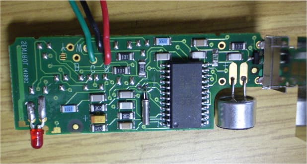
RIYEL2606
Feb 18, 2008Acoustic Glassbreak Sensor
Equipment Class
DSC - Part 15 Security/Remote Control Transmitter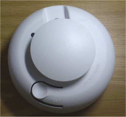
RIYEL2603NA
Feb 18, 2008Smoke Detector
Equipment Class
DSC - Part 15 Security/Remote Control Transmitter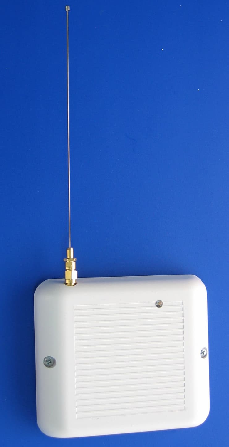
RIYEL2635
Apr 11, 2005Repeater for Wireless Sensors
Equipment Class
DSR - Part 15 Remote Control/Security Device Transceiver
RIYEL2645-PI
Apr 18, 2004PIR Motion Detector
Equipment Class
DSC - Part 15 Security/Remote Control Transmitter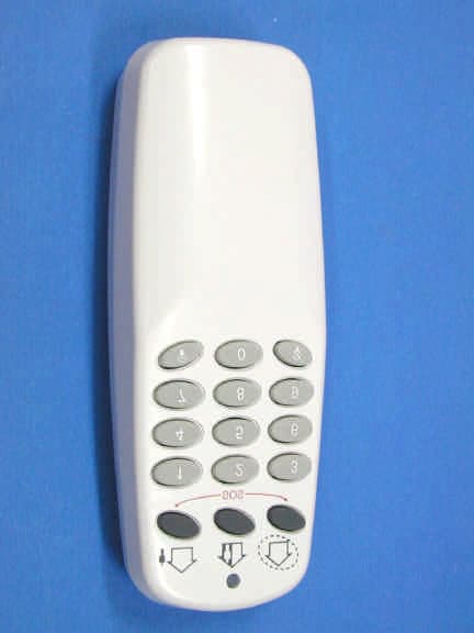
RIYEL2640
Mar 24, 2004Hand Held Security TX
Equipment Class
DSC - Part 15 Security/Remote Control Transmitter