RIYEL2606Acoustic Glassbreak Sensor
Electronics Line 3000 Ltd.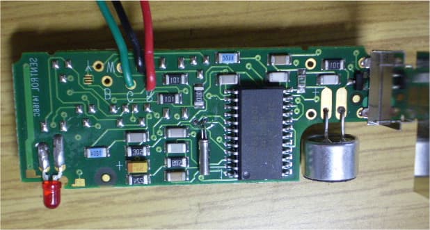
Click to zoom
Application Details
- Equipment Class
- DSC - Part 15 Security/Remote Control Transmitter
- Date of Grant
- Feb 18, 2008
- Application Purpose
- Original Equipment
- Date of Application
- Feb 16, 2008
- Equipment Note
- Acoustic Glassbreak Sensor
- Frequency Range
- 418.00000000 - 418.00000000
- Company
- Electronics Line 3000 Ltd.
- Country
- Israel
Documents & Files
Document Text
Text extracted from the exhibit documents filed with the FCC. Open a document above to read the original.
Users Manual
EL-2606 Electronics Line 3000 Ltd.: 2 Granit Street, Kiryat Arieh, POB 3253, Petah Tikvah 49130 Israel. Tel: (972-3) 918-1333, Fax: (972-3) 922-0831 USA: 5637 Arapahoe Avenue, Boulder, Colorado 80303. Tel: (800) 683-6835, Fax: (303) 938-8062 UK: Unit 7, Leviss Trading Estate, Station Road, Stechford, Bi rmingham B33 9AE. Tel: (44-121) 789-8111, Fax: (44-121) 789-8055 France: ZI-61, rue du Marché Rollay, 94500 Champigny-Sur-Marne. Tel: (33-1) 45.16.19.20, Fax: (33-1) 45.16.19.29 Note: This equipment has been tested and found to comply with the limits for a Class B digital device, pursuant to part 15 of the FC C Rules. These limits are designed to provide reasonable protection agai nst harmful interference in a residential installation. This equipment generates, uses and can radiate radio frequency energy and, if not installed and used in accordance with the instructions, may cause harmful interference to radio communicatio ns. However, there is no guarantee that interference will not occur in a particular installation. If this equipment does cause harmful interference to radio or te levision reception, which can be determined by turning the equipment off and on, the user is encouraged to try to correct the interference by one or more of the following mea sures: 1. Reorient or relocate the receiving antenna, 2. Increase the separation between the equipment and the receiver, 3. Connect th e equipment into an outlet on a circuit different from that to which the receiver is connected, 4. Consult the dealer or an experienced radio/TV technician for help. Warning: Changes or modifications to this equipment not expressly approv ed by the party responsible for compliance (Electronics Line 30 00 Ltd.) could void the user’s authority to operate the equipment. All data is subject to change without prior notice/Ces spécificati ons techniques sont sujettes à modifications sans avis préala ble/Todos estos datos están sujetos a cambio sin preaviso alguno. In no event shall Electronics Line 3000 Ltd. (EL3K) be liable for an amount in excess of EL3K.’s original selling price of this product, for any loss or damage whether direct, indirect, incidental, consequential or otherwise arising out of any failure of the product. Hereby, Electronics Line 3000 Ltd. declares that this sen sor/transmitter is in compliance with the essential requirements and other relevant provisions of Directive 1999/5/EC. 868.35MHz frequency tr ansmitters are not intended for use in Bulgaria, Greece, Pola nd and Slovenia. ZI0592A (01/08) The EL-2606 is a low current acoustic glassbreak sensor with an incorporated wireless transmitter. This unit is designed for use with Electronics Line 3000’s supervised wireless range of receivers. The EL-2606 sends a status transmission to the receiver every hour to indicate that the transmitter is functional. Mounting Considerations The EL-2606 acoustic sensor is omni-directional, providing 360º coverage. The coverage is measured from the sensor to the point on the glass farthest from the sensor. The sensor can be mounted as close as 1m (3.3’) from the glass. Sensor range: • If mounting on the ceiling, the opposite wall or adjoining walls, the maximum range is 6m (20’) for plate, tempered, laminated and wired glass. • For armor-coated glass, the maximum range is 3.65m (12’). Minimum recommended glass size: • 0.3m x 0.6m (1’ x 2’) Glass thickness: • Plate: 2.4mm to 6.4mm (3/32” to 1/4") • Tempered: 3.2mm to 6.4mm (1/8” to 1/4") • Wired: 6.4mm (1/4") • Laminated: 3.2mm to 6.4mm (1/8” to 1/4") For best detection: • The sensor must always be in direct line of sight of all windows to be protected. • If mounting on the wall, try to install the sensor directly opposite the protected window. If this is not possible, adjoining side walls are also a good location. • If mounting on the ceiling, install the sensor 2-3m (6-10’) into the room. • Avoid installing in rooms with lined, insulating or sound deadening drapes. • Avoid installing in rooms with closed wooden window shutters inside. • Avoid installing in the corners of a room. The EL-2606 is best suited to rooms with moderate noise. Note: The sensor may not consistently detect cracks in the glass, bullets which break through the glass or glass breaking around corners and in other rooms. Glassbreak sensors should always be backed up by interior protection. For best false alarm immunity: • Locate the sensor at least 1.2m (4’) away from noise sources (televisions, speakers, sinks, doors, etc.). • Avoid rooms smaller than 3m x 3m (10’ x 10’) and rooms with multiple noise sources. • Do not use where white noise, such as air compressor noise, is present (a blast of compressed air may cause a false alarm). • Do not define the zone as 24hr. It is recommended to register the EL-2606 to a perimeter arming group that arms the perimeter doors and windows of the premises. • Avoid humid rooms – the EL-2606 is not hermetically sealed. Excess moisture can eventually cause a short and a false alarm. Areas to avoid: • Glass airlocks and glass vestibule areas • Noisy kitchens • Residential car garages • Small utility rooms • Stairwells • Small bathrooms • Other small acoustically live rooms For glass break protection in such applications, use shock sensors on the windows or window frames. Installation Instructions 1. Open the housing using a small flat-head screwdriver to separate the base from the cover. 2. Remove the divider separating the battery from the contacts on the battery holder. Note: Due to the occurrence of voltage delay in lithium batteries that have been in storage, the batteries may initially appear to be dead. In this case, press the tamper switch for a few times until the battery voltage level is stabilized. 3. Set the receiver to Registration mode and press the tamper switch twice. Make sure that the Registration procedure is completed (if necessary, press the tamper again). Write the number of the zone on the sticker provided. Affix the sticker inside th…
Text truncated - open the document above for the full version.
Block Diagram
Electronics Line 3000 Ltd. FCC ID:RIYEL2606 Page 1 of 1 EL2606 Glass Break Detector Block Diagram TRANSMITTERCONTROLLERSENSOR BATTERY Antenna 418 MHz
Cover Letter(s)
February 10, 2008 American TCB 6731 Whittier Ave Suite C110 McLean, VA 22101 USA Subject: Request for confidentiality, FCC ID:RIYEL2606 Dear Gentlemen, In regards the exhibits submitted in support of the application for FCC ID:RIYEL2606, please classify the following as permanent confidential under the provision of 47 CFR 0.459: 1) Schematic diagram, file “Schematic_diagram_18074” (1 page); 2) Schematic diagram, file “RF_schematic_diagram_18074” (2 pages) of this Application. The above material contains trade secrets and proprietary information not customarily released to the public. The public disclosure of these matters might be harmful to Electronics Line 3000 Ltd. and provide unjustified benefits to its competitors. Many thanks in advance. Sincerely, Shaul Aviezer Q.A & Approvals manager Electronics Line 3000 Ltd.
Cover Letter(s)
FCC Letter of Authorization 21/10/07 To whom it may concern: We the undersigned, hereby authorize Hermon Laboratories to act on our behalf in all manners relating to application for equipment authorization, including signing of all documents relating to these matters. Any and all acts carried out by Hermon Laboratories, on our behalf shall have the same affect as acts of our own. This authorization is valid until further written notice from Electronics Line 3000 Ltd. Sincerely, Shaul Aviezer Q.A & Approvals
Cover Letter(s)
American Telecommunications Certification Body Inc. 6731 Whittier Ave, McLean, VA 22101 January 7, 2008 RE: Electronics Line 3000 Ltd. FCC ID: RIYEL2606 After a review of the submitted information, I have a few comments on the above referenced Application. Depending on your responses, kindly understand there may be additional comments. 1) One labeling exhibit appears to have 2 different ID numbers. Another labeling exhibit does not have sufficient resolution to read the label. Please review as information should only support the device being certified and be of sufficient resolution. 2) Schematic of the RF board itself does not appear to be provided. Please provide. 3) According to the users manual, when the device is powered up, it continues in a tamper mode for about 5 minutes where it transmits every few seconds. This may violate 15.231 requirements. Even professionally installed devices have a 10 second limitation per event (i.e. button push / automatic start up, etc.). Note test data suggests < 5 seconds. Please review. 4) For spurious emissions, the tables suggest there was not data. However plots are given and some data should be shown in effort to show this data is compliant. Timothy R. Johnson Examining Engineer mailto: [email protected] The items indicated above must be submitted before processing can continue on the above referenced application. Failure to provide the requested information may result in application termination. Correspondence should be considered part of the permanent submission and may be viewed from the Internet after a Grant of Equipment Authorization is issued. Please do not respond to this correspondence using the email reply button. In order for your response to be processed expeditiously, you must submit your documents through the AmericanTCB.com website. Also, please note that partial responses increase processing time and should not be submitted. Any questions about the content of this correspondence should be directed to the sender.
Cover Letter(s)
American Telecommunications Certification Body Inc. 6731 Whittier Ave, McLean, VA 22101 February 6, 2008 RE: Electronics Line 3000 Ltd. FCC ID: RIYEL2606 After a review of the submitted information, I have a few comments on the above referenced Application. Depending on your responses, kindly understand there may be additional comments. 1) Regarding the schematic, U2 is actually a daughter board containing the TX RF circuit. Note that a schematic for the TX portion of the device is required as specified 2.1033(b)(5) for the RF section. Please provide. Timothy R. Johnson Examining Engineer mailto: [email protected] The items indicated above must be submitted before processing can continue on the above referenced application. Failure to provide the requested information may result in application termination. Correspondence should be considered part of the permanent submission and may be viewed from the Internet after a Grant of Equipment Authorization is issued. Please do not respond to this correspondence using the email reply button. In order for your response to be processed expeditiously, you must submit your documents through the AmericanTCB.com website. Also, please note that partial responses increase processing time and should not be submitted. Any questions about the content of this correspondence should be directed to the sender.
Cover Letter(s)
HERM O N LA BO RA TO RIES February 4, 2008 American TCB 6731 Whittier Ave Suite C110 McLean, VA 22101 Attn: Mr. T. Johnson, Examining Engineer RE: your e-mail dated January 7, 2008; Electronics Line 3000 Ltd. FCC ID:RIYEL2606, ATCB005790 Dear Mr. Johnson, Please find below the answers to your questions. 1) The corrected file “Label_location_18074_rev1” was uploaded on February 4, 2008. 2) The applicant confirms that the file “Schematic_diagram_18074” does include RF part (utilizes U2 of AT1466 type as shown in “Operational_description_18074”). 3) The adjusted file “User_manual_18074_rev1” was uploaded on February 4, 2008. 4) The adjusted test report “ELERAD_FCC.18074_rev1” with corrected Table 7.2.3 was uploaded on February 4, 2008. Sincerely, Marina Cherniavsky, certification engineer Hermon Laboratories
Cover Letter(s)
HERM O N LA BO RA TO RIES February 11, 2008 American TCB 6731 Whittier Ave Suite C110 McLean, VA 22101 Attn: Mr. T. Johnson, Examining Engineer RE: your e-mail dated February 6, 2008; Electronics Line 3000 Ltd. FCC ID:RIYEL2606, ATCB005790 Dear Mr. Johnson, Please find below the answers to your questions. 1) File “RF_schematic_diagram_18074” was uploaded on February 11, 2008. 2) The adjusted file “Confidentiality_letter_18074_rev1” was uploaded on February 11, 2008 via Additional information folder. Sincerely, Marina Cherniavsky, certification engineer Hermon Laboratories
External Photos
Electronics Line 3000 Ltd. FCC ID:RIYEL2606 Date: December 2007 Page 1 of 3 EXTERNAL PHOTOGRAPHS This document contains 2 photographs Electronics Line 3000 Ltd. FCC ID:RIYEL2606 Date: December 2007 Page 2 of 3 Photograph No.1 EL2606 glass break sensor front view Electronics Line 3000 Ltd. FCC ID:RIYEL2606 Date: December 2007 Page 3 of 3 Photograph No.2 EL2606 glass break sensor rear side view
ID Label/Location Info
Electronics Line 3000 Ltd. FCC ID:RIYEL2606 Date: December 2007 Page 1 of 1 EL2606 sensor label Label location The label with FCC ID:RIYEL2606 will be located on the sensor rear side as shown below. FCC ID:RIYEL2606
Internal Photos
Electronics Line 3000 Ltd. FCC ID:RIYEL2606 Date: December 2007 Page 1 of 11 INTERNAL PHOTOGRAPHS This document contains 10 photographs Electronics Line 3000 Ltd. FCC ID:RIYEL2606 Date: December 2007 Page 2 of 11 Photograph No.1 EL2606 glass break sensor internal view Electronics Line 3000 Ltd. FCC ID:RIYEL2606 Date: December 2007 Page 3 of 11 Photograph No.2 EL2606 main PCB without battery Electronics Line 3000 Ltd. FCC ID:RIYEL2606 Date: December 2007 Page 4 of 11 Photograph No.3 EL2606 main PCB without battery compartment Electronics Line 3000 Ltd. FCC ID:RIYEL2606 Date: December 2007 Page 5 of 11 Photograph No.4 EL2606 main PCB rear side view Electronics Line 3000 Ltd. FCC ID:RIYEL2606 Date: December 2007 Page 6 of 11 Photograph No.5 EL2606 main PCB side view with RF module and antenna Electronics Line 3000 Ltd. FCC ID:RIYEL2606 Date: December 2007 Page 7 of 11 Photograph No.6 EL2606 RF module Electronics Line 3000 Ltd. FCC ID:RIYEL2606 Date: December 2007 Page 8 of 11 Photograph No.7 RF PCB second side Electronics Line 3000 Ltd. FCC ID:RIYEL2606 Date: December 2007 Page 9 of 11 Photograph No.8 EL2606 sensor PCB front view Electronics Line 3000 Ltd. FCC ID:RIYEL2606 Date: December 2007 Page 10 of 11 Photograph No.9 EL2606 sensor PCB front view with shield removed Electronics Line 3000 Ltd. FCC ID:RIYEL2606 Date: December 2007 Page 11 of 11 Photograph No.10 EL2606 sensor PCB second side view
Operational Description
Electronics Line 3000 Ltd. FCC ID:RIYEL2606 Page 1 of 1 EL2606 glass break sensor operational description This document describes the operation of the EL2606 according to the block diagram shown below. The transmitter operates at 418 MHz (utilizes U2 of AT1466 type as shown in the RF schematic diagram) and it is FM modulated. The antenna is internal whip of 67 mm length. The glass break sensor is Interlogix 5845. The sensor feeds a controller port. The controller is Microchip PIC16LF628A. Sensor detection causes the controller to activate the transmitter. A 3.6V/1200mAh 1/2AA Lithium battery, model TL-4902, manufactured by Tadiran feeds the detector. TRANSMITTERCONTROLLERSENSOR BATTERY Antenna
Test Report
Hermon Laboratories Ltd. Harakevet Industrial Zone, Binyamina 30500, Israel Tel. +972-4-6288001 Fax. +972-4-6288277 E-mail: [email protected] Page 1 of 48 Report ID: ELERAD_FCC.18074_rev1.doc Date of Issue: 11/14/2007 Electrical 839.01 TEST REPORT ACCORDING TO: FCC CFR 47 PART 15 Subpart C, section 15.231 and subpart B FOR: Electronics Line 3000 Ltd. Wireless acoustic glassbreak sensor Model:EL2606 This report is in conformity with ISO/ IEC 17025. The "A2LA Accredited" symbol endorsement applies only to the tests and calibrations that are listed in the scope of Hermon Laboratories accreditation. The test results relate only to the items tested. This test report shall not be reproduced in any form except in full with the written approval of Hermon Laboratories Ltd. Report ID: ELERAD_FCC.18074_rev1.doc Date of Issue: 11/14/2007 Page 2 of 48 Table of contents 1 Applicant information..................................................................................................................................................... 3 2 Equipment under test attributes .................................................................................................................................... 3 3 Manufacturer information .............................................................................................................................................. 3 4 Test details.................................................................................................................................................................... 3 5 Tests summary.............................................................................................................................................................. 4 6 EUT description............................................................................................................................................................. 5 6.1 General information....................................................................................................................................................... 5 6.2 Test configuration.......................................................................................................................................................... 5 6.3 Changes made in the EUT ............................................................................................................................................ 5 6.4 Transmitter characteristics ............................................................................................................................................ 6 7 Transmitter tests according to 47CFR part 15 subpart C requirements ........................................................................ 7 7.1 Periodic operation requirements ................................................................................................................................... 7 7.2 Field strength of emissions.......................................................................................................................................... 12 7.3 Occupied bandwidth test ............................................................................................................................................. 30 7.4 Antenna requirements ................................................................................................................................................. 33 7.5 Radiated emission measurements .............................................................................................................................. 34 8 APPENDIX A Test equipment and ancillaries used for tests....................................................................................... 39 9 APPENDIX B Measurement uncertainties................................................................................................................... 40 10 APPENDIX C Test laboratory description ................................................................................................................... 41 11 APPENDIX D Specification references ....................................................................................................................... 41 12 APPENDIX E Test equipment correction factors......................................................................................................... 42 13 APPENDIX F Abbreviations and acronyms................................................................................................................. 48 Report ID: ELERAD_FCC.18074_rev1.doc Date of Issue: 11/14/2007 Page 3 of 48 1 Applicant information Client name: Electronics Line 3000 Ltd. Address: P.O.Box 3253, 58 Amal street, Petah Tikva, 49130, Israel Telephone: +972 3921 1117 Fax: +972 3921 2224 E-mail: [email protected] Contact name: Mr. Shaul Aviezer 2 Equipment under test attributes Product name: Wireless acoustic glassbreak sensor Product type: Transmitter Model(s): EL2606 Part number: EH020C Software release: GE008 Receipt date 7/16/2007 3 Manufacturer information Manufacturer name: Electronics Line 3000 Ltd. Address: P.O.Box 3253, 58 Amal street, Petah Tikva, 49130, Israel Telephone: +972 3921 1117 Fax: +972 3921 2224 E-Mail: [email protected] Contact name: Mr. Shaul Aviezer 4 Test details Project ID: 18074 Location: Hermon Laboratories Ltd. Harakevet Industrial Zone, Binyamina 30500, Israel Test started: 7/16/2007 Test completed: 11/04/2007 Test specification(s): FCC Part 15, subpart C, ß15.231; subpart B, ß15.109 Report ID: ELERAD_FCC.18074_rev1.doc Date of Issue: 11/14/2007 Page 4 of 48 5 Tests summary Test Status Transmitter characteristics Section 15.231(a), Periodic operation requirements Pass Section 15.231(b), Field strength of emissions Pass Section 15.231(c), Occupied bandwidth Pass Section 15.207(a), Conducted emission Not required Section 15.203, Antenna requirement Pass Unintentional emissions Section 15…
Text truncated - open the document above for the full version.
Test Setup Photos
Electronics Line 3000 Ltd. FCC ID:RIYEL2606 Date: December 2007 Page 1 of 9 SETUP PHOTOGRAPHS This document contains 8 photographs Electronics Line 3000 Ltd. FCC ID:RIYEL2606 Date: December 2007 Page 2 of 9 Photograph No.1 Occupied bandwidth measurement setup Electronics Line 3000 Ltd. FCC ID:RIYEL2606 Date: December 2007 Page 3 of 9 Photograph No.2 Spurious radiated emissions measurement setup in the anechoic chamber in 9 kHz to 30 MHz band Electronics Line 3000 Ltd. FCC ID:RIYEL2606 Date: December 2007 Page 4 of 9 Photograph No.3 Radiated emissions measurement setup in the anechoic chamber in 30 MHz to 1000 MHz band Electronics Line 3000 Ltd. FCC ID:RIYEL2606 Date: December 2007 Page 5 of 9 Photograph No.4 Spurious emission field strength measurement setup in the anechoic chamber above 1000 MHz Electronics Line 3000 Ltd. FCC ID:RIYEL2606 Date: December 2007 Page 6 of 9 Photograph No.5 Spurious emission field strength measurement setup at the OATS in X-axis position Electronics Line 3000 Ltd. FCC ID:RIYEL2606 Date: December 2007 Page 7 of 9 Photograph No.6 Spurious emission field strength measurement setup at the OATS in Y-axis position Electronics Line 3000 Ltd. FCC ID:RIYEL2606 Date: December 2007 Page 8 of 9 Photograph No.7 Spurious emission field strength measurement setup at the OATS in Z-axis position Electronics Line 3000 Ltd. FCC ID:RIYEL2606 Date: December 2007 Page 9 of 9 Photograph No.8 Spurious emission field strength measurement setup at the OATS
Contact Information
Applicant
Shaul Aviezer(Quality & Approvals Manager)
Technical Contact
Hermon LaboratoriesAlex Usoskin
[email protected]972-4628-8001
Harakevet Industrial zone · Binyamina · Israel
Non-Technical Contact
Electronics Line 3000 Ltd.Shaul Aviezer
[email protected]972 3921 1117
Test Firm
Hermon Laboratories Ltd.Alexander Usoskin
Technical Specifications
| # | Rule Parts | Frequency Range | Power Output |
|---|---|---|---|
| 1 | 15.231 | 418 MHz - 418 MHz | - |
Other Applications from Electronics Line 3000 Ltd.
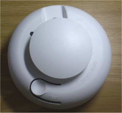
RIYEL2603NA
Feb 18, 2008Smoke Detector
Equipment Class
DSC - Part 15 Security/Remote Control Transmitter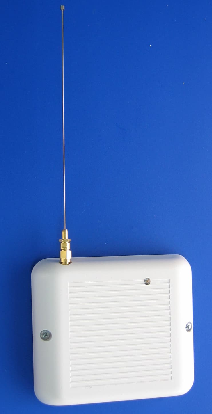
RIYEL2635
Apr 11, 2005Repeater for Wireless Sensors
Equipment Class
DSR - Part 15 Remote Control/Security Device Transceiver
RIYEL2645-PI
Apr 18, 2004PIR Motion Detector
Equipment Class
DSC - Part 15 Security/Remote Control Transmitter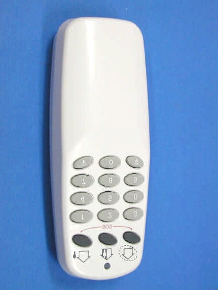
RIYEL2640
Mar 24, 2004Hand Held Security TX
Equipment Class
DSC - Part 15 Security/Remote Control Transmitter
RIYEL2620
Mar 24, 2004Security Keypad
Equipment Class
DSC - Part 15 Security/Remote Control Transmitter