RIYEL2603NASmoke Detector
Electronics Line 3000 Ltd.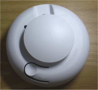
Click to zoom
Application Details
- Equipment Class
- DSC - Part 15 Security/Remote Control Transmitter
- Date of Grant
- Feb 18, 2008
- Application Purpose
- Original Equipment
- Date of Application
- Feb 16, 2008
- Equipment Note
- Smoke Detector
- Frequency Range
- 418.00000000 - 418.00000000
- Company
- Electronics Line 3000 Ltd.
- Country
- Israel
Documents & Files
Document Text
Text extracted from the exhibit documents filed with the FCC. Open a document above to read the original.
Users Manual
Introduction The EL-2603NA is a smoke detector and transmitter designed for use with Electronics Line 3000’s supervised wireless range of receivers. The EL-2603NA sends a status transmission to the receiver every hour to indicate that the transmitter is functional. Smoke Detector/Base Lock discourages unauthorized removal of the transmitter or of the batteries by requiring a screwdriver to remove the detector from the base. Please read this guide thoroughly before proceeding with the installation. Internal Signal Outputs The smoke detector is listed with a transmitter that provides the following signals for interfacing: • Alarm • Alarm restore • Low battery • Supervision check-in The following procedure explains the installation of the EL-2603NA wireless smoke detector and its registration to the receiver, selecting location, test procedures, attaching and removing, maintenance and specifications. Selecting a Location Selecting a suitable location is critical to the operation of smoke detectors. This equipment should be installed in accordance with the National Fire Protection Association's (NFA) Standard 72. Where to Locate the Required Smoke Detectors in Existing Construction. The major threat from fire in a family living unit occurs at night when everyone is asleep. The principal threat to persons in sleeping areas comes from fires in the remainder of the unit. Therefore, a smoke detector(s) is best located between the bedroom areas and the rest of the unit. In units with only one bedroom area on one floor, the smoke detector(s) should be located as shown in Figure 1A. In family living units with more than one bedroom area or with bedrooms on more than one floor, more than one smoke detector is required, as shown in Figure 1 B. In addition to smoke detectors outside of the sleeping areas, the installation of a smoke detector on each additional story of the family living unit, including the basement, is required. These installations are shown in Figure 1 C. The living area smoke detector should be installed in the living room or near the stairway to the upper level, or in both locations. The basement smoke detector should be installed in close proximity to the stairway leading to the floor above. Where installed on an open- joisted ceiling, the detector should be placed on the bottom of the joists. The detector should be positioned relative to the stairway to intercept smoke coming from a fire in the basement before the smoke enters the stairway. Where to Locate the Required Smoke Detectors in New Construction All of the smoke detectors specified in this section for existing construction are required and, in addition, a smoke detector is required in each bedroom. Are more Smoke Detectors Desirable? The required number of smoke detectors might not provide reliable early warning protection for those areas separated by a door from the areas protected by the required smoke detectors. For this reason, it is recommended that the householder consider the use of additional smoke detectors for those areas for increased protection. The additional areas include the basement, bedrooms, dining room, furnace room, utility room, and hallways not protected by the required smoke detectors. The installation of smoke detectors in kitchens, attics (finished or unfinished), or garages is not normally recommended, as these locations occasionally experience conditions that can result in improper operation. , Regulations pertaining to smoke detector installations vary from state to state. For more information, contact your local fire department or local authority having jurisdiction. In addition to NFA 72, use the following location guidelines to optimize performance and reduce the chance of false alarms from the detector: • Locate ceiling-mounted smoke detectors in the center of a room or hallway at least 4 inches (10cm) from any walls or partitions. • Locate wall-mounted smoke detectors so the top of the detector is 4 to 12 inches (10 to 30cm) below the ceiling. • Locate in a suitable environment as follows: • - Temperature between 40°F (4.4°C) and 100°F (37.8°C) • - Humidity between 0 and 95% non-condensing Figure1A: One-BedroomArea Figure 1 B: More Than One Bedroom Area Figure 1 C: More Than One Story • Locate away from air conditioners, heating registers, and any other ventilation source that may interfere with smoke entering the detector. • Mount smoke detectors on a firm permanent surface. • Locate away from large metallic objects. Attaching and Removing Attaching Attach the mounting base to the ceiling using the screws provided. Attach the EL-2603NA to its mounting base. To do so, line up the raised tab on the lip of the detector with the slot/arrow on the lip of the mounting base. Insert the detector into the base and turn clockwise approximately 15 degrees. It should snap firmly into place. , The Detector cannot be attached to the mounting base if no batteries are installed because of the chance of false alarms from the detector: LED The LED on the Detector indicates the status of the alarm as follows: Flashing – Flashes every 9 seconds to indicate normal operation. ON – detects smoke. OFF – Trouble or maintenance is required. Removing Remove the red plastic dust cover from the detector. The detector is shipped with a dust cover for protection on construction sites with dusty environments. Remove the EL-2603NA smoke detector from its mounting base. To do so, grasp the detector and turn it counterclockwise approximately 15 degrees. The detector should snap off of the mounting base. To remove the detector from the mounting base when the detector/base lock is used, insert a small screwdriver into the locking tab slot on the side of the base and press in while simultaneously turning the detector counterclockwise 15 degrees. See Figure 2 When to Replace the Batteries The detector requires two 3V lithium A batteries as listed on the battery compartment cover, with the exception of the Energizer brand batt…
Text truncated - open the document above for the full version.
Block Diagram
Electronics Line 3000 Ltd. FCC ID:RIYEL2603NA Page 1 of 1 EL2603NA Smoke Detector Block Diagram TRANSMITTERCONTROLLERSENSOR BATTERY Antenna 418 MHz
Cover Letter(s)
FCC Letter of Authorization 21/10/07 To whom it may concern: We the undersigned, hereby authorize Hermon Laboratories to act on our behalf in all manners relating to application for equipment authorization, including signing of all documents relating to these matters. Any and all acts carried out by Hermon Laboratories, on our behalf shall have the same affect as acts of our own. This authorization is valid until further written notice from Electronics Line 3000 Ltd. Sincerely, Shaul Aviezer Q.A & Approvals
Cover Letter(s)
February 10, 2008 American TCB 6731 Whittier Ave Suite C110 McLean, VA 22101 USA Subject: Request for confidentiality, FCC ID:RIYEL2603NA Dear Gentlemen, In regards the exhibits submitted in support of the application for FCC ID:RIYEL2603NA, please classify the following as permanent confidential under the provision of 47 CFR 0.459: 1) Schematic diagram, file “Schematic_diagram_18073” (2 pages) 2) Schematic diagram, file “RF_schematic_diagram_18073” (2 pages) of this Application. The above material contains trade secrets and proprietary information not customarily released to the public. The public disclosure of these matters might be harmful to Electronics Line 3000 Ltd. and provide unjustified benefits to its competitors. Many thanks in advance. Sincerely, Shaul Aviezer Q.A & Approvals manager Electronics Line 3000 Ltd.
Cover Letter(s)
American Telecommunications Certification Body Inc. 6731 Whittier Ave, McLean, VA 22101 January 7, 2008 RE: Electronics Line 3000 Ltd. FCC ID: RIYEL2603NA After a review of the submitted information, I have a few comments on the above referenced Application. Depending on your responses, kindly understand there may be additional comments. 1) Label appears to have 2 different ID numbers. Please review as information should only support the device being certified. 2) Schematic of the RF board itself does not appear to be provided. Please provide. 3) According to the users manual, when the device is powered up, it continues in a test mode for about 5 minutes where it transmits every few seconds. This violates 15.231 requirements. Even professionally installed devices have a 10 second limitation per event (i.e. button push / automatic start up, etc.). Note test data suggests < 10 seconds, but this can not be firmly verified given presentation of the data. Please review. 4) For spurious emissions, the tables suggest there was not data. However plots are given and some data should be shown in effort to show this data is compliant. Timothy R. Johnson Examining Engineer mailto: [email protected] The items indicated above must be submitted before processing can continue on the above referenced application. Failure to provide the requested information may result in application termination. Correspondence should be considered part of the permanent submission and may be viewed from the Internet after a Grant of Equipment Authorization is issued. Please do not respond to this correspondence using the email reply button. In order for your response to be processed expeditiously, you must submit your documents through the AmericanTCB.com website. Also, please note that partial responses increase processing time and should not be submitted. Any questions about the content of this correspondence should be directed to the sender.
Cover Letter(s)
American Telecommunications Certification Body Inc. 6731 Whittier Ave, McLean, VA 22101 February 6, 2008 RE: Electronics Line 3000 Ltd. FCC ID: RIYEL2603NA After a review of the submitted information, I have a few comments on the above referenced Application. Depending on your responses, kindly understand there may be additional comments. 1) Regarding the schematic, TX1 is actually a daughter board containing the TX RF circuit. Note that a schematic for the TX portion of the device is required as specified 2.1033(b)(5) for the RF section. Please provide. Timothy R. Johnson Examining Engineer mailto: [email protected] The items indicated above must be submitted before processing can continue on the above referenced application. Failure to provide the requested information may result in application termination. Correspondence should be considered part of the permanent submission and may be viewed from the Internet after a Grant of Equipment Authorization is issued. Please do not respond to this correspondence using the email reply button. In order for your response to be processed expeditiously, you must submit your documents through the AmericanTCB.com website. Also, please note that partial responses increase processing time and should not be submitted. Any questions about the content of this correspondence should be directed to the sender.
Cover Letter(s)
HERM O N LA BO RA TO RIES February 4, 2008 American TCB 6731 Whittier Ave Suite C110 McLean, VA 22101 Attn: Mr. T. Johnson, Examining Engineer RE: your e-mail dated January 7, 2008; Electronics Line 3000 Ltd. FCC ID:RIYEL2603NA, ATCB005789 Dear Mr. Johnson, Please find below the answers to your questions. 1) The corrected file “Label_location_18073_rev1” was uploaded on February 4, 2008. 2) The applicant confirms that the file “Schematic_diagram_18073” does include RF part (ANT1, connected components and TX1 module, MLX418MHz, AT1553). 3) The adjusted file “User_manual_18073_rev1” was uploaded on February 4, 2008. 4) The adjusted test report “ELERAD_FCC.18073_rev1” with corrected Table 7.2.3 was uploaded on February 4, 2008. Sincerely, Marina Cherniavsky, certification engineer Hermon Laboratories
Cover Letter(s)
HERM O N LA BO RA TO RIES February 11, 2008 American TCB 6731 Whittier Ave Suite C110 McLean, VA 22101 Attn: Mr. T. Johnson, Examining Engineer RE: your e-mail dated February 6, 2008; Electronics Line 3000 Ltd. FCC ID:RIYEL2603NA, ATCB005789 Dear Mr. Johnson, Please find below the answers to your questions. 1) File “RF_schematic_diagram_18073” was uploaded on February 11, 2008. 2) The adjusted “Confidentiality_letter_18073_rev1” was uploaded on February 11, 2008 via Additional information folder. Sincerely, Marina Cherniavsky, certification engineer Hermon Laboratories
External Photos
Electronics Line 3000 Ltd. FCC ID:RIYEL2603NA Date: December 2007 Page 1 of 4 EXTERNAL PHOTOGRAPHS This document contains 3 photographs Electronics Line 3000 Ltd. FCC ID:RIYEL2603NA Date: December 2007 Page 2 of 4 Photograph No.1 EL2603NA smoke detector general view Electronics Line 3000 Ltd. FCC ID:RIYEL2603NA Date: December 2007 Page 3 of 4 Photograph No.2 EL2603NA smoke detector top view Electronics Line 3000 Ltd. FCC ID:RIYEL2603NA Date: December 2007 Page 4 of 4 Photograph No.3 EL2603NA smoke detector rear side view
ID Label/Location Info
Electronics Line 3000 Ltd. FCC ID:RIYEL2603NA Date: December 2007 Page 1 of 2 EL2603NA detector label Electronics Line 3000 Ltd. FCC ID:RIYEL2603NA Date: December 2007 Page 2 of 2 Label location The label with FCC ID:RIYEL2603NA will be located in the detector as shown below. FCC ID:RIYEL2603NA
Internal Photos
Electronics Line 3000 Ltd. FCC ID:RIYEL2603NA Date: December 2007 Page 1 of 12 INTERNAL PHOTOGRAPHS This document contains 11 photographs Electronics Line 3000 Ltd. FCC ID:RIYEL2603NA Date: December 2007 Page 2 of 12 Photograph No.1 EL2603 smoke detector without rear cover Electronics Line 3000 Ltd. FCC ID:RIYEL2603NA Date: December 2007 Page 3 of 12 Photograph No.2 EL2603 smoke detector with cover removed Electronics Line 3000 Ltd. FCC ID:RIYEL2603NA Date: December 2007 Page 4 of 12 Photograph No.3 EL2603 smoke detector internal view Electronics Line 3000 Ltd. FCC ID:RIYEL2603NA Date: December 2007 Page 5 of 12 Photograph No.4 EL2603 smoke detector side view with antenna Electronics Line 3000 Ltd. FCC ID:RIYEL2603NA Date: December 2007 Page 6 of 12 Photograph No.5 EL2603 sensor PCB Electronics Line 3000 Ltd. FCC ID:RIYEL2603NA Date: December 2007 Page 7 of 12 Photograph No.6 EL2603 sensor PCB second side Electronics Line 3000 Ltd. FCC ID:RIYEL2603NA Date: December 2007 Page 8 of 12 Photograph No.7 Main PCB with RF card Electronics Line 3000 Ltd. FCC ID:RIYEL2603NA Date: December 2007 Page 9 of 12 Photograph No.8 Main PCB second side Electronics Line 3000 Ltd. FCC ID:RIYEL2603NA Date: December 2007 Page 10 of 12 Photograph No.9 RF PCB front view Electronics Line 3000 Ltd. FCC ID:RIYEL2603NA Date: December 2007 Page 11 of 12 Photograph No.10 RF PCB with shield removed Electronics Line 3000 Ltd. FCC ID:RIYEL2603NA Date: December 2007 Page 12 of 12 Photograph No.11 RF PCB second side view
Operational Description
Electronics Line 3000 Ltd. FCC ID:RIYEL2603NA Page 1 of 1 EL2603NA smoke detector operational description This document describes the operation of the EL2603NA smoke detector according to the block diagram shown below. The transmitter operates at 418 MHz and it is FM modulated. The antenna is internal whip of 130 mm length. The smoke sensor is Interlogix ESL560NS. The sensor feeds a controller port. The controller is Microchip PIC16LF628A. Sensor detection causes the controller to activate the transmitter. Two 3V/1500mAh 2/3AA Lithium batteries feed the detector. TRANSMITTERCONTROLLERSENSOR BATTERY Antenna
Test Report
Hermon Laboratories Ltd. Harakevet Industrial Zone, Binyamina 30500, Israel Tel. +972-4-6288001 Fax. +972-4-6288277 E-mail: [email protected] Page 1 of 47 Report ID: ELERAD_FCC.18073_rev1.doc Date of Issue: 11/25/2007 Electrical 839.01 TEST REPORT ACCORDING TO: FCC CFR 47 PART 15 Subpart C, section 15.231 and subpart B FOR: Electronics Line 3000 Ltd. Wireless Smoke Detector Model: EL-2603NA This report is in conformity with ISO/ IEC 17025. The "A2LA Accredited" symbol endorsement applies only to the tests and calibrations that are listed in the scope of Hermon Laboratories accreditation. The test results relate only to the items tested. This test report shall not be reproduced in any form except in full with the written approval of Hermon Laboratories Ltd. Report ID: ELERAD_FCC.18073_rev1.doc Date of Issue: 11/25/2007 Page 2 of 47 Table of contents 1 Applicant information..................................................................................................................................................... 3 2 Equipment under test attributes .................................................................................................................................... 3 3 Manufacturer information .............................................................................................................................................. 3 4 Test details.................................................................................................................................................................... 3 5 Tests summary.............................................................................................................................................................. 4 6 EUT description............................................................................................................................................................. 5 6.1 General information....................................................................................................................................................... 5 6.2 Test configuration.......................................................................................................................................................... 5 6.3 Transmitter characteristics ............................................................................................................................................ 7 6.4 Changes made in the EUT ............................................................................................................................................ 7 7 Transmitter tests according to 47CFR part 15 subpart C requirements ........................................................................ 8 7.1 Periodic operation requirements ................................................................................................................................... 8 7.2 Field strength of emissions.......................................................................................................................................... 12 7.3 Occupied bandwidth test ............................................................................................................................................. 29 7.4 Antenna requirements ................................................................................................................................................. 32 7.5 Radiated emission measurements .............................................................................................................................. 33 8 APPENDIX A Test equipment and ancillaries used for tests....................................................................................... 38 9 APPENDIX B Measurement uncertainties................................................................................................................... 39 10 APPENDIX C Test laboratory description ................................................................................................................... 40 11 APPENDIX D Specification references ....................................................................................................................... 40 12 APPENDIX E Test equipment correction factors......................................................................................................... 41 13 APPENDIX F Abbreviations and acronyms................................................................................................................. 47 Report ID: ELERAD_FCC.18073_rev1.doc Date of Issue: 11/25/2007 Page 3 of 47 1 Applicant information Client name: Electronics Line 3000 Ltd. Address: P.O.Box 3253, 58 Amal street, Petah Tikva, 49130, Israel Telephone: +972 3921 1117 Fax: +972 3921 2224 E-mail: [email protected] Contact name: Mr. Shaul Aviezer 2 Equipment under test attributes Product name: Wireless smoke detector Product type: Transmitter Model(s): EL-2603NA Serial number: EU595B Software release: GD008 Receipt date 7/16/2007 3 Manufacturer information Manufacturer name: Electronics Line 3000 Ltd. Address: P.O.Box 3253, 58 Amal street, Petah Tikva, 49130, Israel Telephone: +972 3921 1117 Fax: +972 3921 2224 E-Mail: [email protected] Contact name: Mr. Shaul Aviezer 4 Test details Project ID: 18073 Location: Hermon Laboratories Ltd. Harakevet Industrial Zone, Binyamina 30500, Israel Test started: 7/16/2007 Test completed: 11/04/2007 Test specification(s): FCC Part 15, subpart C, ß15.231; subpart B, ß15.109 Report ID: ELERAD_FCC.18073_rev1.doc Date of Issue: 11/25/2007 Page 4 of 47 5 Tests summary Test Status Transmitter characteristics Section 15.231(a), Periodic operation requirements Pass Section 15.231(b), Field strength of emissions Pass Section 15.231(c), Occupied bandwidth Pass Section 15.207(a), Conducted emission Not required Section 15.203, Antenna requirement Pass Unintentional emissions Section 15.107, Conducted…
Text truncated - open the document above for the full version.
Test Setup Photos
Electronics Line 3000 Ltd. FCC ID:RIYEL2603NA Date: December 2007 Page 1 of 10 SETUP PHOTOGRAPHS This document contains 9 photographs Electronics Line 3000 Ltd. FCC ID:RIYEL2603NA Date: December 2007 Page 2 of 10 Photograph No.1 Occupied bandwidth measurement setup Electronics Line 3000 Ltd. FCC ID:RIYEL2603NA Date: December 2007 Page 3 of 10 Photograph No.2 Spurious radiated emissions measurement setup in the anechoic chamber in 9 kHz to 30 MHz band Electronics Line 3000 Ltd. FCC ID:RIYEL2603NA Date: December 2007 Page 4 of 10 Photograph No.3 Radiated emissions measurement setup in the anechoic chamber in 30 MHz to 1000 MHz band Electronics Line 3000 Ltd. FCC ID:RIYEL2603NA Date: December 2007 Page 5 of 10 Photograph No.4 Spurious emission field strength measurement setup in the anechoic chamber above 1000 MHz Electronics Line 3000 Ltd. FCC ID:RIYEL2603NA Date: December 2007 Page 6 of 10 Photograph No.5 Spurious emission field strength measurement setup at the OATS in X-axis position Electronics Line 3000 Ltd. FCC ID:RIYEL2603NA Date: December 2007 Page 7 of 10 Photograph No.6 Spurious emission field strength measurement setup at the OATS in Y-axis position Electronics Line 3000 Ltd. FCC ID:RIYEL2603NA Date: December 2007 Page 8 of 10 Photograph No.7 Spurious emission field strength measurement setup at the OATS in Z-axis position Electronics Line 3000 Ltd. FCC ID:RIYEL2603NA Date: December 2007 Page 9 of 10 Photograph No.8 Radiated emission field strength measurement setup at the OATS with log-periodic antenna Electronics Line 3000 Ltd. FCC ID:RIYEL2603NA Date: December 2007 Page 10 of 10 Photograph No.9 Spurious emission field strength measurement setup at the OATS with double ridge guide antenna
Contact Information
Applicant
Shaul Aviezer(Quality & Approvals Manager)
Technical Contact
Hermon LaboratoriesAlex Usoskin
[email protected]972-4628-8001
Harakevet Industrial zone · Binyamina · Israel
Non-Technical Contact
Electronics Line 3000 Ltd.Shaul Aviezer
[email protected]927 3921 1117
Test Firm
Hermon Laboratories Ltd.Alexander Usoskin
Technical Specifications
| # | Rule Parts | Frequency Range | Power Output |
|---|---|---|---|
| 1 | 15.231 | 418 MHz - 418 MHz | - |
Other Applications from Electronics Line 3000 Ltd.
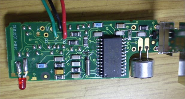
RIYEL2606
Feb 18, 2008Acoustic Glassbreak Sensor
Equipment Class
DSC - Part 15 Security/Remote Control Transmitter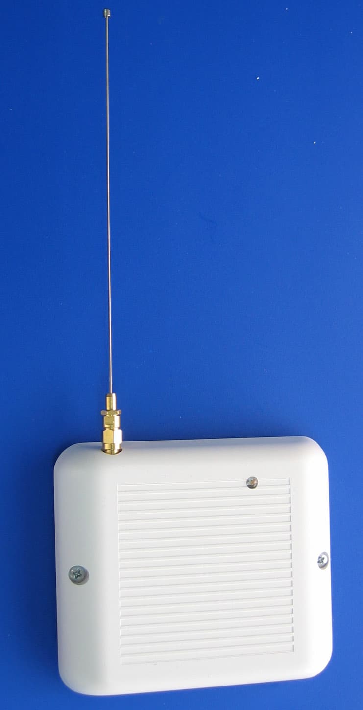
RIYEL2635
Apr 11, 2005Repeater for Wireless Sensors
Equipment Class
DSR - Part 15 Remote Control/Security Device Transceiver
RIYEL2645-PI
Apr 18, 2004PIR Motion Detector
Equipment Class
DSC - Part 15 Security/Remote Control Transmitter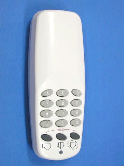
RIYEL2640
Mar 24, 2004Hand Held Security TX
Equipment Class
DSC - Part 15 Security/Remote Control Transmitter
RIYEL2620
Mar 24, 2004Security Keypad
Equipment Class
DSC - Part 15 Security/Remote Control Transmitter