RVW2202ABGNortel Networks WLAN-Mobile Adapter 2202
Nortel Networks, Inc.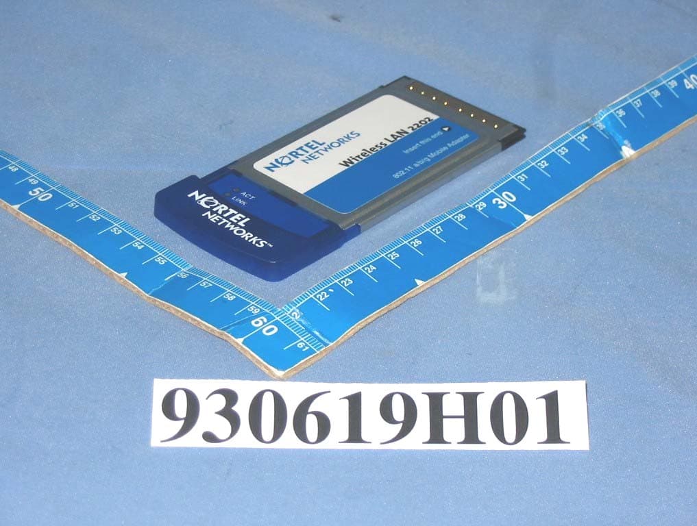
Click to zoom
Application Details
- Equipment Class
- DTS - Digital Transmission System
- Date of Grant
- Dec 06, 2004
- Application Purpose
- Original Equipment
- Date of Application
- Oct 05, 2004
- Equipment Note
- Nortel Networks WLAN-Mobile Adapter 2202
- Frequency Range
- 5725.00000000 - 5850.00000000
- Company
- Nortel Networks, Inc.
- Country
- United States
Documents & Files
Document Text
Text extracted from the exhibit documents filed with the FCC. Open a document above to read the original.
Users Manual
Preliminary Draft - Nortel Networks Confidential Part No. 216669-A September 2004 4655 Great America Parkway Santa Clara, CA 95054 Installing and Using the Nortel Networks Wireless LAN Mobile Adapter 2202 Release 3.0.0.0 2 216669-A Preliminary Draft - Nortel Networks Confidential Copyright © 2004 Nortel Networks All rights reserved. September 2004. The information in this document is subject to change without notice. The statements, configurations, technical data, and recommendations in this document are believed to be accurate and reliable, but are presented without express or implied warranty. Users must take full responsibility for their applications of any products specified in this document. The information in this document is proprietary to Nortel Networks NA Inc. The software described in this document is furnished under a license agreement and may be used only in accordance with the terms of that license. The software license agreement is included in this document. Trademarks Nortel Networks and the Nortel Networks logos are trademarks of Nortel Networks. Adobe and Acrobat are trademarks of Adobe Systems Incorporated,Windows 2000 and Windows XP are trademarks of Microsoft Corp, and Pentium is a trademark of Intel. Nortel Networks and the Nortel Networks logo are trademarks of Nortel Networks, Inc. All other trademarks and registered trademarks are the property of their respective owners. Asterisks denote trademarks. Statement of Conditions In the interest of improving internal design, operational function, and/or reliability, Nortel Networks NA Inc. reserves the right to make changes to the products described in this document without notice. Nortel Networks NA Inc. does not assume any liability that may occur due to the use or application of the product(s) or circuit layout(s) described herein. Compliances Federal Communication Commission Interference Statement This equipment has been tested and found to comply with the limits for a Class B digital device, pursuant to Part 15 of the FCC Rules. These limits are designed to provide reasonable protection against harmful interference in a residential installation. This equipment generates, uses and can radiate radio frequency energy and, if not installed and used in accordance with the instructions, may cause harmful interference to radio communications. However, there is no guarantee that interference will not occur in a particular installation. If this equipment does cause harmful interference to radio or television reception, which can be determined by turning the equipment off and on, the user is encouraged to try to correct the interference by one of the following measures: •Reorient or relocate the receiving antenna. •Increase the separation between the equipment and receiver. •Connect the equipment into an outlet on a circuit different from that to which the receiver is connected. •Consult the dealer or an experienced radio/TV technician for help. FCC Caution: Any changes or modifications not expressly approved by the party responsible for compliance could void the user's authority to operate this equipment. For operation within 5.15 ~ 5.25GHz frequency range, it is restricted to indoor environment, and the antenna of this device must be integral. This device complies with Part 15 of the FCC Rules. Operation is subject to the following two conditions: (1) This device may not cause harmful interference, and (2) this device must accept any interference received, including interference that may cause undesired operation. 3 Installing and Using the Nortel Networks Wireless LAN Mobile Adapter 2202 Preliminary Draft - Nortel Networks Confidential IMPORTANT NOTE: FCC Radiation Exposure Statement This equipment complies with FCC radiation exposure limits set forth for an uncontrolled environment. This device complies with FCC RF Exposure limits set forth for an uncontrolled environment, under 47 CFR 2.1093 paragraph (d)(2). This transmitter must not be co-located or operating in conjunction with any other antenna or transmitter. Nortel declared that WLAN-Mobile Adapter 2202 is limited in CH1~11 by specified firmware controlled in USA from 2400~2483.5MHz. Nortel declared that WLAN-Mobile Adapter 2202 has been disabled for operation in the USA in the 5.470~5.725 MHz UNII band by specified firmware control. This equipment has been SAR-evaluated for use in laptops (notebooks) with side slot configuration. Exposure to Radio Frequency Radiation The radiated output power of the Nortel Networks Wireless LAN Mobile Adapter 2202 radio is far below the FCC radio frequency exposure limits. Nevertheless, the wireless radio shall be used in such a manner that the potential for human contact during normal operation is minimized. The Nortel Networks Wireless LAN Mobile Adapter 2202 radio operates within guidelines found in radio frequency safety standards and recommendations, which reflect the consensus of the scientific community. Nortel Networks therefore believes the internal wireless radio is safe for use by consumers. The level of energy emitted is far less than the electromagnetic energy emitted by wireless devices such as mobile phones. However, the use of wireless radios may be restricted in some situations or environments, such as aboard airplanes. If you are unsure of restrictions, you are encouraged to ask for authorization before turning on the wireless radio. European Community Notice Marking by the symbol indicates compliance with the Essential Requirements of the R&TTE Directive of the European Union (1999/5/EC). This equipment meets the following conformance standards: EN 301 893, EN 301 489-17, EN 60950, ETS 300 328-2 This device should not be operated in 802.11a mode in the following European Community countries: Greece. The radio spectrum authorities in these countries do not currently allow operation of this radio device in the 5GHz bands. This device is restricted to indoor use when operated in the European Community using channe…
Text truncated - open the document above for the full version.
External Photos
Page 1 CONSTRUCTION PHOTOS OF EUT
ID Label/Location Info
(Fig. 1) FCC ID: RVW2202ABG LABEL LOCATION Label
ID Label/Location Info
6 4 . 6 0 m m
Internal Photos
Page 2 Page 3 Page 4
Operational Description
FCC ID: RVW2202ABG Report No. 930619H01 Technical Description This device is a Nortel Networks WLAN-Mobile Adapter 2202 operates in both the 5GHz and 2.4GHz bands with DSSS and OFDM technique. The transmitter rate could be 1/2/5.5/6/9/11/12/18/24/36/48/54Mbps, and the maximum data rate could be up to 108Mbps in turbo mode. The transmitter of the EUT is powered by host equipment. The antenna is Dualband PCB antenna without connector. Under normal use condition, the user has to keep at least 20 cm separation distance between radiator and the body of the user. For more detailed instruction, please refer to the user’s manual. FCC 15.407(c) states : The device shall automatically discontinue transmission in case of either absence of information to transmit or operational failure. These provisions are not intended to preclude the transmission of control or signaling information or the use of repetitive codes used by certain digital technologies to complete frame or burst intervals. Applicants shall include in their application for equipment authorization a description of hoe this requirement is met. Data transmission is always initiated by software, which is then pass down through the MAC, through the digital and analog baseband, and finally to the RF chip. Several special packets (ACKs, CTS, PSPoll, etc...) are initiated by the MAC. There are the only ways the digital baseband portion will turn on the RF transmitter, which it then turns off at the end of the packet. Therefore, the transmitter will be on only while one of the aforementioned packets are being transmitted.
RF Exposure Info
FCC ID: RVW2202ABG Report No.: SA930619H011Issued: Sep. 15, 2004 SAR TEST REPORT REPORT NO.: SA930619H01 MODEL NO.: WLAN-Mobile Adapter 2202 OEM MODEL NO.: WN6301C-26B RECEIVED: Jun. 19, 2004 TESTED: Aug. 11, 2004 APPLICANT: Nortel Networks Inc. ADDRESS: 4655 Great America Parkway, Santa Clara, CA 95054, U.S.A ISSUED BY: Advance Data Technology Corporation LAB ADDRESS: No. 47, 14th Ling, Chia Pau Tsuen, Lin Kou Hsiang 244, Taipei Hsien, Taiwan, R.O.C. TEST LOCATION: No. 19, Hwa Ya 2 nd Rd., Wen Hwa Tsuen, Kwei Shan Hsiang, Taoyuan Hsien 333, Taiwan, R.O.C. This test report consists of 48 pages in total except Appendix. It may be duplicated completely for legal use with the approval of the applicant. It should not be reproduced except in full, without the written approval of our laboratory. The client should not use it to claim product endorsement by CNLA, A2LA or any government agencies. The test results in the report only apply to the tested sample. 0528 ILAC MRA No. 2177-01 FCC ID: RVW2202ABG Report No.: SA930619H012Issued: Sep. 15, 2004 Table of Contents 1.CERTIFICATION .........................................................................................................3 2.GENERAL INFORMATION..........................................................................................4 2.1 GENERAL DESCRIPTION OF EUT............................................................................4 2.2 GENERAL DESCRIPTION OF APPLIED STANDARDS .............................................5 2.3 GENERAL INOFRMATION OF THE SAR SYSTEM ...................................................6 2.4 GENERAL DESCRIPTION OF THE SPATIAL PEAK SAR EVALUATION ................12 3.DESCRIPTION OF TEST MODES AND CONFIGURATIONS ..................................16 4.DESCRIPTION OF SUPPORT UNITS ......................................................................20 5.TEST RESULTS ........................................................................................................21 5.1 TEST PROCEDURES ...............................................................................................21 5.2 MEASURED SAR RESULT .......................................................................................22 5.3 SAR LIMITS...............................................................................................................31 5.4 RECIPES FOR TISSUE SIMULATING LIQUIDS ......................................................31 5.5 TEST EQUIPMENT FOR TISSUE PROPERTY ........................................................35 6.SYSTEM VALIDATION ..............................................................................................36 6.1 TEST EQUIPMENT ...................................................................................................36 6.2 TEST PROCEDURE .................................................................................................36 6.3 VALIDATION RESULT...............................................................................................38 6.4 SYSTEM VALIDATION UNCERTAINTIES ................................................................40 7.MEASUREMENT SAR PROCEDURE UNCERTAINTIES.........................................41 7.1 PROBE CALIBRATION UNCERTAINTY ...................................................................41 7.2 ISOTROPY UNCERTAINTY......................................................................................41 7.3 BOUNDARY EFFECT UNCERTAINTY .....................................................................42 7.4 PROBE LINEARITY UNCERTAINTY ........................................................................42 7.5 READOUT ELECTRONICS UNCERTAINTY ............................................................42 7.6 RESPONSE TIME UNCERTAINTY...........................................................................43 7.7 INTEGRATION TIME UNCERTAINTY ......................................................................44 7.8 PROBE POSITIONER MECHANICAL TOLERANCE................................................44 7.9 PROBE POSITIONING .............................................................................................45 7.10 PHANTOM UNCERTAINTY ......................................................................................45 7.11 DASY4 UNCERTAINTY BUDGET.............................................................................46 8.INFORMATION ON THE TESTING LABORATORIES ..............................................47 APPENDIX A: TEST CONFIGURATIONS AND TEST DATA APPENDIX B: ADT SAR MEASUREMENT SYSTEM APPENDIX C: PHOTOGRAPHS OF SYSTEM VALIDATION APPENDIX D: SYSTEM CERTIFICATE & CALIBRATION FCC ID: RVW2202ABG Report No.: SA930619H013Issued: Sep. 15, 2004 1. CERTIFICATION PRODUCT : Nortel Networks WLAN-Mobile Adapter 2202 MODEL NO. : WLAN-Mobile Adapter 2202 BRAND NAME : Nortel Networks OEM MODEL NO. : WN6301C-26B OEM BRAND NAME : Arcadyan APPLICANT : Nortel Networks Inc. TESTED: Aug. 11, 2004 TEST ITEM : ENGINEERING SAMPLE STANDARDS : FCC Part 2 (Section 2.1093), FCC OET Bulletin 65, Supplement C (01-01), RSS-102 The above equipment (Model no.: WLAN-Mobile Adapter 2202) has been tested by Advance Data Technology Corporation, and found compliance with the requirement of the above standards. The test record, data evaluation & Equipment Under Test (EUT) configurations represented herein are true and accurate accounts of the measurements of the sample’s EMC characteristics under the conditions specified in this report. PREPARED BY:, DATE:Sep. 15, 2004 Stephanie Hung TECHNICAL ACCEPTANCE:, DATE:Sep. 15, 2004 Responsible for RF Ansen Lei APPROVED BY:, DATE:Sep. 15, 2004 Cody Chang / Deputy Manager FCC ID: RVW2202ABG Report No.: SA930619H014Issued: Sep. 15, 2004 2. GENERAL INFORMATION 2.1 GENERAL DESCRIPTION OF EUT PRODUCT Nortel Networks WLAN-Mobile Adapter 2202 MODEL NO. WLAN-Mobile Adapter 2202 OEM MODEL NO. WN6301C-26B POWER SUPPLY 3.3 Vdc from host equipment CLASSIFICATION Portable device, production unit MODULATI…
Text truncated - open the document above for the full version.
RF Exposure Info
Page 1 APPENDIX A1: TEST CONFIGURATIONS AND TEST DATA A1: TEST CONFIGURATION Mode 1 Dell C600 Bottom Position The bottom of the EUT to the flat phantom distance 12 mm Page 2 Mode 2 Dell C600 Tip Position The tip of the EUT to the flat phantom distance 0 mm Page 3 Mode 3 Dell C600 Bottom Position The bottom of the EUT to the flat phantom distance 12 mm Page 4 Mode 4 Dell C600 Tip Position The tip of the EUT to the flat phantom distance 0 mm Page 5 Mode 5 Dell D600 Bottom Position The bottom of the EUT to the flat phantom distance 15 mm Page 6 Mode 6 Dell D600 Tip Position The tip of the EUT to the flat phantom distance 0 mm Page 7 Mode 7 Dell D600 Bottom Position The bottom of the EUT to the flat phantom distance 15 mm Page 8 Mode 8 Dell D600 Tip Position The tip of the EUT to the flat phantom distance 0 mm Page 9 Mode 9 Compaq N800C Bottom Position The bottom of the EUT to the flat phantom distance 11 mm Page 10 Mode 10 Compaq N800C Tip Position The tip of the EUT to the flat phantom distance 0 mm Page 11 Mode 11 Compaq N800C Bottom Position The bottom of the EUT to the flat phantom distance 11 mm Page 12 Mode 12 Compaq N800C Tip Position The tip of the EUT to the flat phantom distance 0 mm Page 13 EUT Photo Page 14 Liquid Level Photo MSL2450MHz D=155mm Date/Time: 08/04/04 15:50:56 Test Laboratory: Advance Data Technology WLAN-Mobile Adapter 2202 Dell C600 11b Bottom - Mode 1 Ch 1 DUT: Nortel Networks WLAN-Mobile Adapter 2202 ; Type: WLAN-Mobile Adapter 2202 ; Test Channel Frequency: 2412 MHz Communication System: 802.11b ; Frequency: 2412 MHz ; Duty Cycle: 1:1 ; Modulation type: CCK Medium: MSL2450 (ı = 1.9352 mho/m, İ r = 53.1265, ȡ = 1000 kg/m 3 ) ; Liquid level : 155mm Phantom section: Flat Section ; Separation distance : 12 mm (The bottom side of the EUT to the Phantom) Antenna type : Internal Antenna ; Air temp. : 22.0 degrees ; Liquid temp. : 21.0 degrees DASY4 Configuration: - Probe: ET3DV6 - SN1790 ; ConvF(4.4, 4.4, 4.4) ; Calibrated: 2003/8/29 - Sensor-Surface: 4mm (Mechanical Surface Detection) - Electronics: DAE3 Sn579 ; Calibrated: 2003/8/15 - Phantom: SAM 12 ; Type: SAM V4.0 ; Serial: TP 1202 - Measurement SW: DASY4, V4.1 Build 47 ; Postprocessing SW: SEMCAD, V1.6 Build 115 Low Channel/Area Scan (7x11x1): Measurement grid: dx=15mm, dy=15mm Reference Value = 9.45 V/m Power Drift = -0.2 dB Maximum value of SAR = 0.522 mW/g Low Channel/Zoon Scan (7x7x7)/Cube 0: Measurement grid: dx=5mm, dy=5mm, dz=5mm Peak SAR (extrapolated) = 1.03 W/kg SAR(1 g) = 0.461 mW/g; SAR(10 g) = 0.235 mW/g Reference Value = 9.45 V/m Power Drift = -0.2 dB Maximum value of SAR = 0.486 mW/g A2 : TEST DATA Date/Time: 08/04/04 16:16:26 Test Laboratory: Advance Data Technology WLAN-Mobile Adapter 2202 Dell C600 11b Bottom - Mode 1 Ch 6 DUT: Nortel Networks WLAN-Mobile Adapter 2202 ; Type: WLAN-Mobile Adapter 2202 ; Test Channel Frequency: 2437 MHz Communication System: 802.11b ; Frequency: 2437 MHz ; Duty Cycle: 1:1 ; Modulation type: CCK Medium: MSL2450 (ı = 1.9677 mho/m, İ r = 53.0061, ȡ = 1000 kg/m 3 ) ; Liquid level : 155mm Phantom section: Flat Section ; Separation distance : 12 mm (The bottom side of the EUT to the Phantom) Antenna type : Internal Antenna ; Air temp. : 22.0 degrees ; Liquid temp. : 21.0 degrees DASY4 Configuration: - Probe: ET3DV6 - SN1790 ; ConvF(4.4, 4.4, 4.4) ; Calibrated: 2003/8/29 - Sensor-Surface: 4mm (Mechanical Surface Detection) - Electronics: DAE3 Sn579 ; Calibrated: 2003/8/15 - Phantom: SAM 12 ; Type: SAM V4.0 ; Serial: TP 1202 - Measurement SW: DASY4, V4.1 Build 47 ; Postprocessing SW: SEMCAD, V1.6 Build 115 Middle Channel/Area Scan (7x11x1): Measurement grid: dx=15mm, dy=15mm Reference Value = 9.02 V/m Power Drift = -0.2 dB Maximum value of SAR = 0.467 mW/g Middle Channel/Zoon Scan (7x7x7)/Cube 0: Measurement grid: dx=5mm, dy=5mm, dz=5mm Peak SAR (extrapolated) = 0.943 W/kg SAR(1 g) = 0.425 mW/g; SAR(10 g) = 0.217 mW/g Reference Value = 9.02 V/m Power Drift = -0.2 dB Maximum value of SAR = 0.443 mW/g Date/Time: 08/04/04 16:45:36 Test Laboratory: Advance Data Technology WLAN-Mobile Adapter 2202 Dell C600 11b Bottom - Mode 1 Ch 11 DUT: Nortel Networks WLAN-Mobile Adapter 2202 ; Type: WLAN-Mobile Adapter 2202 ; Test Channel Frequency: 2462 MHz Communication System: 802.11b ; Frequency: 2462 MHz ; Duty Cycle: 1:1 ; Modulation type: CCK Medium: MSL2450 (ı = 2.0037 mho/m, İ r = 52.8612, ȡ = 1000 kg/m 3 ) ; Liquid level : 155mm Phantom section: Flat Section ; Separation distance : 12 mm (The bottom side of the EUT to the Phantom) Antenna type : Internal Antenna ; Air temp. : 22.0 degrees ; Liquid temp. : 21.0 degrees DASY4 Configuration: - Probe: ET3DV6 - SN1790 ; ConvF(4.4, 4.4, 4.4) ; Calibrated: 2003/8/29 - Sensor-Surface: 4mm (Mechanical Surface Detection) - Electronics: DAE3 Sn579 ; Calibrated: 2003/8/15 - Phantom: SAM 12 ; Type: SAM V4.0 ; Serial: TP 1202 - Measurement SW: DASY4, V4.1 Build 47 ; Postprocessing SW: SEMCAD, V1.6 Build 115 High Channel/Area Scan (7x11x1): Measurement grid: dx=15mm, dy=15mm Reference Value = 8.88 V/m Power Drift = -0.2 dB Maximum value of SAR = 0.547 mW/g High Channel/Zoon Scan (7x7x7)/Cube 0: Measurement grid: dx=5mm, dy=5mm, dz=5mm Peak SAR (extrapolated) = 1.15 W/kg SAR(1 g) = 0.466 mW/g; SAR(10 g) = 0.236 mW/g Reference Value = 8.88 V/m Power Drift = -0.2 dB Maximum value of SAR = 0.5 mW/g Date/Time: 08/04/04 14:04:12 Test Laboratory: Advance Data Technology WLAN-Mobile Adapter 2202 Dell C600 11b Tip - Mode 2 Ch 1 DUT: Nortel Networks WLAN-Mobile Adapter 2202 ; Type: WLAN-Mobile Adapter 2202 ; Test Channel Frequency: 2412 MHz Communication System: 802.11b ; Frequency: 2412 MHz; Duty Cycle: 1:1; Modulation type: CCK Medium: MSL2450 (ı = 1.9352 mho/m, İ r = 53.1265, ȡ = 1000 kg/m 3 ) ; Liquid level : 155 mm Phantom section: Flat Section ; Separation distance : 0 mm (The tip of the EUT to the Phantom) Antenna type : Internal Antenna ; Air temp. : 22.0 degrees ; Liquid temp. : 21.0 degrees DASY4 Configuration: - Probe: ET3DV6 - SN1790 ; ConvF(…
Text truncated - open the document above for the full version.
Test Report
FCC ID: RVW2202ABG Report No.: RF930619H01 1 Issued: Sep. 15, 2004 FCC TEST REPORT REPORT NO.:RF930619H01 MODEL NO.:WLAN-Mobile Adapter 2202, WN6301C-26B RECEIVED:Jul. 19, 2004 TESTED:Jun. 25 to Jul. 29, 2004 and Sep. 07, 2004 APPLICANT: Nortel Networks Inc. ADDRESS: 4655 Great America Parkway Santa Clara CA 95054 USA ISSUED BY: Advance Data Technology Corporation LAB LOCATION: No. 81-1, Lu Liao Keng, 9 Ling, Wu Lung Tsuen, Chiung Lin Hsiang, Hsin Chu Hsien, Taiwan, R.O.C. This test report consists of 166 pages in total. It may be duplicated completely for legal use with the approval of the applicant. It should not be reproduced except in full, without the written approval of our laboratory. The client should not use it to claim product endorsement by CNLA, A2LA or any government agencies. The test results in the report only apply to the tested sample. The test results in this report are traceable to the national or international standards. 0536 No. 2177-01 ILAC MRA FCC ID: RVW2202ABG Report No.: RF930619H01 2 Issued: Sep. 15, 2004 Table of Contents 1. CERTIFICATION .................................................................................................................... 6 2. SUMMARY OF TEST RESULTS............................................................................................ 7 3. GENERAL INFORMATION .................................................................................................. 10 3.1 GENERAL DESCRIPTION OF EUT..................................................................................... 10 3.2 DESCRIPTION OF TEST MODES....................................................................................... 12 3.3 GENERAL DESCRIPTION OF APPLIED STANDARDS...................................................... 13 3.4 DESCRIPTION OF SUPPORT UNITS................................................................................. 14 3.5 CONFIGURATION OF SYSTEM UNDER TEST.................................................................. 14 4. TEST TYPES AND RESULTS (FOR PART 802.11B) .......................................................... 15 4.1 CONDUCTED EMISSION MEASUREMENT....................................................................... 15 4.1.1 LIMITS OF CONDUCTED EMISSION MEASUREMENT .................................................... 15 4.1.2 TEST INSTRUMENTS .........................................................................................................15 4.1.3 TEST PROCEDURES ..........................................................................................................16 4.1.4 DEVIATION FROM TEST STANDARD ................................................................................ 16 4.1.5 TEST SETUP ....................................................................................................................... 17 4.1.6 EUT OPERATING CONDITIONS......................................................................................... 17 4.1.7 TEST RESULTS ................................................................................................................... 18 4.2 RADIATED EMISSION MEASUREMENT ............................................................................ 20 4.2.1 LIMITS OF RADIATED EMISSION MEASUREMENT ......................................................... 20 4.2.2 TEST INSTRUMENTS .........................................................................................................21 4.2.3 TEST PROCEDURES ..........................................................................................................22 4.2.4 DEVIATION FROM TEST STANDARD ................................................................................ 22 4.2.5 TEST SETUP ....................................................................................................................... 23 4.2.6 EUT OPERATING CONDITIONS......................................................................................... 23 4.2.7 TEST RESULTS ................................................................................................................... 24 4.2.8 TEST RESULTS - DSSS ......................................................................................................25 4.2.9 TEST RESULTS - OFDM ..................................................................................................... 28 4.3 6DB BANDWIDTH MEASUREMENT................................................................................... 32 4.3.1 LIMITS OF 6DB BANDWIDTH MEASUREMENT ................................................................ 32 4.3.2 TEST INSTRUMENTS .........................................................................................................32 4.3.3 TEST PROCEDURE ............................................................................................................ 33 4.3.4 DEVIATION FROM TEST STANDARD ................................................................................ 33 4.3.5 TEST SETUP ....................................................................................................................... 33 4.3.6 EUT OPERATING CONDITIONS......................................................................................... 33 4.3.7 TEST RESULTS -DSSS .......................................................................................................34 4.3.8 TEST RESULTS -OFDM ...................................................................................................... 38 4.4 MAXIMUM PEAK OUTPUT POWER ................................................................................... 43 4.4.1 LIMITS OF MAXIMUM PEAK OUTPUT POWER MEASUREMENT ................................... 43 4.4.2 INSTRUMENTS.................................................................................................................... 43 4.4.3 TEST PROCEDURES ..........................................................................................................44 4.4.4 TE…
Text truncated - open the document above for the full version.
Test Setup Photos
FCC ID: RVW2202ABG Report No.: RF930619H01 164 Issued: Sep. 15, 2004 6. PHOTOGRAPHS OF THE TEST CONFIGURATION CONDUCTED EMISSION TEST FCC ID: RVW2202ABG Report No.: RF930619H01 165 Issued: Sep. 15, 2004 RADIATED EMISSION TEST
Contact Information
Applicant
Claudio Morfe(Assistant Secretary)
Technical Contact
Advance Data Technology CorporationEric Lin
[email protected]+886 3 593 5343
81-1 Luliaoken, 9th Lane, Wulung Tsuen · Hsinchu · Taiwan
Test Firm
Bureau Veritas CPS (H.K.) Ltd. Taoyuan BranchRichard Chen
Technical Specifications
| # | Rule Parts | Frequency Range | Power Output |
|---|---|---|---|
| 2 | 15C | 5.72 GHz - 5.85 GHz | 82.00 mW |
Other Applications from Nortel Networks, Inc.
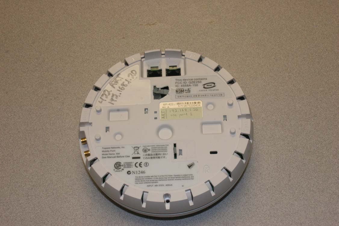
RVW2332
Sep 11, 2007802.11 A/B/G Access Point
Equipment Class
DTS - Digital Transmission System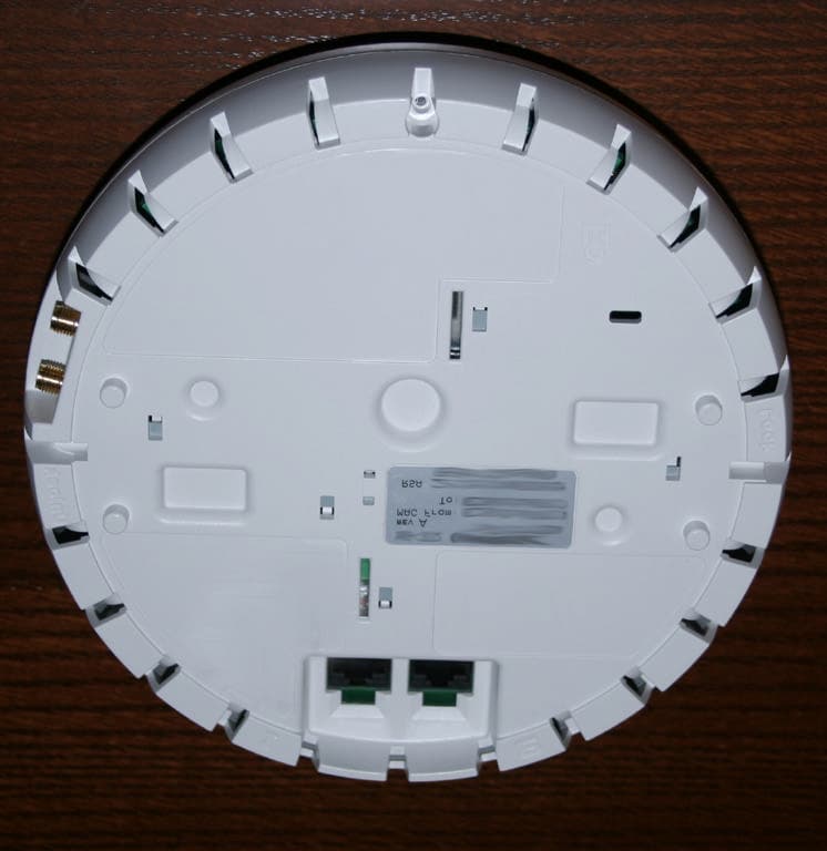
RVW2330
Sep 27, 2005Dual Band Access Point
Equipment Class
DTS - Digital Transmission System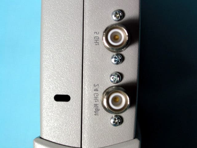
RVW2230W
Jun 19, 2004802.11 Dual Band Access Point
Equipment Class
NII - Unlicensed National Information Infrastructure TX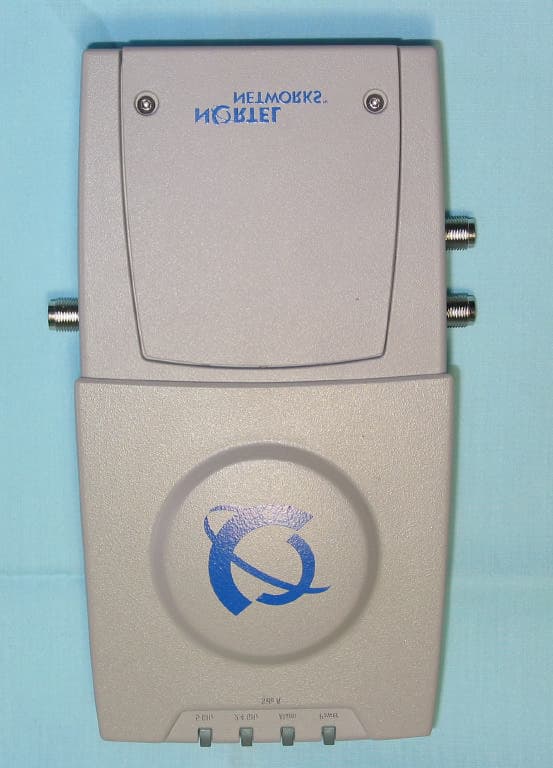
RVW2230
Mar 25, 2004802.11 Dual Band Access Point
Equipment Class
NII - Unlicensed National Information Infrastructure TX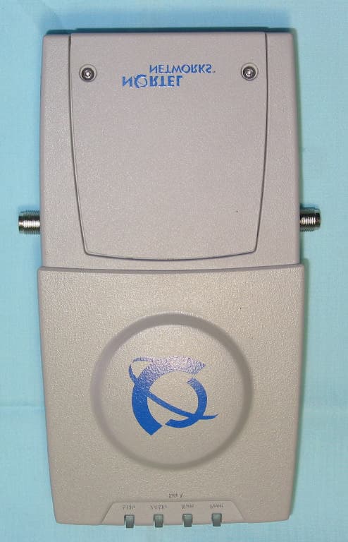
RVW2231
Mar 25, 20042.4 GHz 802.11 Access Point
Equipment Class
DTS - Digital Transmission System