RVW2330Dual Band Access Point
Nortel Networks, Inc.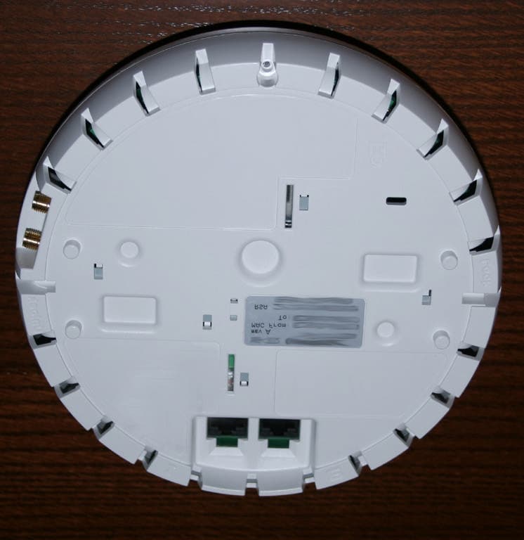
Click to zoom
Application Details
- Equipment Class
- DTS - Digital Transmission System
- Date of Grant
- Sep 27, 2005
- Application Purpose
- Original Equipment
- Date of Application
- Sep 27, 2005
- Equipment Note
- Dual Band Access Point
- Frequency Range
- 5745.00000000 - 5825.00000000
- Company
- Nortel Networks, Inc.
- Country
- United States
Documents & Files
Document Text
Text extracted from the exhibit documents filed with the FCC. Open a document above to read the original.
Users Manual
Part No. 320662-A May 2005 4655 Great America Parkway Santa Clara, CA 95054 *320662-A* Nortel WLAN—Access Point 2330 Quick Installation Guide 2 320662-A Copyright © Nortel Networks Limited 2005. All rights reserved. The information in this document is subject to change without notice. The statements, configurations, technical data, and recommendations in this document are believed to be accurate and reliable, but are presented without express or implied warranty. Users must take full responsibility for their applications of any products specified in this document. The information in this document is proprietary to Nortel. Trademarks Nortel Networks, the Nortel logo, the Globemark, and Unified Networks are trademarks of Nortel Microsoft, Windows, and Windows NT are trademarks of Microsoft Corporation. Adobe and Acrobat Reader are trademarks of Adobe Systems Incorporated. All other trademarks and registered trademarks are property of their respective owners. The asterisk after a name denotes a trademarked item. Restricted rights legend Use, duplication, or disclosure by the United States Government is subject to restrictions as set forth in subparagraph (c)(1)(ii) of the Rights in Technical Data and Computer Software clause at DFARS 252.227-7013. Notwithstanding any other license agreement that may pertain to, or accompany the delivery of, this computer software, the rights of the United States Government regarding its use, reproduction, and disclosure are as set forth in the Commercial Computer Software-Restricted Rights clause at FAR 52.227-19. Statement of conditions In the interest of improving internal design, operational function, and/or reliability, Nortel Inc. reserves the right to make changes to the products described in this document without notice. Nortel Inc. does not assume any liability that may occur due to the use or application of the product(s) or circuit layout(s) described herein. Portions of the code in this software product may be Copyright © 1988, Regents of the University of California. All rights reserved. Redistribution and use in source and binary forms of such portions are permitted, provided that the above copyright notice and this paragraph are duplicated in all such forms and that any documentation, advertising materials, and other materials related to such distribution and use acknowledge that such portions of the software were developed by the University of California, Berkeley. The name of the University may not be used to endorse or promote products derived from such portions of the software without specific prior written permission. SUCH PORTIONS OF THE SOFTWARE ARE PROVIDED “AS IS” AND WITHOUT ANY EXPRESS OR IMPLIED WARRANTIES, INCLUDING, WITHOUT LIMITATION, THE IMPLIED WARRANTIES OF MERCHANTABILITY AND FITNESS FOR A PARTICULAR PURPOSE. In addition, the program and information contained herein are licensed only pursuant to a license agreement that contains restrictions on use and disclosure (that may incorporate by reference certain limitations and notices imposed by third parties). 3 Nortel WLAN—Access Point 2330 Quick Installation Guide Regulatory Compliance Statements for WLAN Access Point 2330 Federal Communications Commission (FCC) Compliance Notices This section includes the following FCC statements for the WLAN Access Point 2330: • Class B Interference Statement • RF Radiation Exposure & Hazard Warning • Non-Modification Statement • Deployment Statement Class B Interference Statement This equipment has been tested and found to comply with the limits for a Class B digital device, pursuant to Part 15 of the FCC Rules. These limits are designed to provide reasonable protection against harmful interference when the equipment is operated in either a commercial or residential environment. This equipment generates, uses, and can radiate radio frequency energy and, if not installed and used in accordance with the instructions, may cause harmful interference to radio communications. However, there is no guarantee that interference will not occur in a particular installation. If this equipment does cause harmful interference to radio communications, which can be determined by turning the equipment off and on, the user is encouraged to try to correct the interference by one of the following measures: • Reorient or relocate the receiving antenna. • Increase the separation between the equipment and receiver. • Connect the equipment into an outlet on a circuit different from that to which the receiver is connected. • Consult the dealer or an experienced radio communications technician for help. FCC Caution: This device complies with Part 15 of the FCC Rules. Operation is subject to the following two conditions: (1) This device may not cause harmful interference, and (2) this device must accept any interference received, including interference that may cause undesired operation. RF Radiation Exposure & Hazard Statement To ensure compliance with FCC RF exposure requirements, this device must be installed in a location such that the antenna of the device will be greater than 20 cm (8 in.) from all persons. Using higher gain antennas and types of antennas not covered under the FCC certification of this product is not allowed. Installers of the radio and end users of the product must adhere to the installation instructions provided in this manual. This transmitter must not be co-located or operating in conjunction with any other antenna or transmitter. Non-Modification Statement Use only the supplied internal antenna, or external antennas supplied by the manufacturer. Unauthorized antennas, modifications, or attachments could damage the WLAN Access Point 2330 and violate FCC regulations. Any changes or modifications not expressly approved by the party responsible for compliance could void the user's authority to operate this equipment. 4 320662-A Deployment Statement This product is certified for indoor deployment only. Do not install or use this product outdoors.…
Text truncated - open the document above for the full version.
Attestation Statements
23 Aug 2005 To: Federal Communications Commission Industrie Canada From: Nortel Networks Subject: Professional Installation and Configuration FCC ID: RVW2330 IC: 332R-2330 Gentlemen, The purpose of this letter is to address power reduction concerns when using high gain antennas on the 5.15 to 5.25 GHz UNII band. The current FCC and Industrie Canada rules allow an RF transmit power of +17 dBm when operating within the 5.15 – 5.25 GHz band. Additionally, the FCC and Industrie Canada require that the RF transmit power limit be reduced 1dB for every additional dBi or antenna gain above 6 dBi. A similar reduction in power is required for operation in the 5.25 – 5.35 band from a level of 24 dBm for antenna gains over 6 dBi. In order to comply with the FCC requirements regarding maximum transmit power limit, it is necessary to reduce the RF transmit power when using the access point with the antennas ( or an antenna of similar type and gain). The following table outlines the maximum RF transmit power limits for the 5.15 – 5.25 GHz “802.11 A” band with the indicated antennas. Mfg. Part No. Type Specified Antenna Gain (dBi) Power Limit Reduction (dB) 5.15 - 5.25 GHz Max RF Power Allowed (dBm) 5.25 - 5.35 GHz Max RF Power Allowed (dBm) Cushcraft S51514WPN36RSM Panel 14 8 9 16 Cushcraft S5153WPBN36RSM Omni 6 0 17 24 Nortel is cognizant of the fact that Nortel is responsible for continued compliance on the access point even when installed in the field. In order to ensure that the Nortel installation meet the FCC and Industrie Canada regulatory requirements, the configuration of the access points to the correct transmit power for a given antenna will be performed by a trained professional installer. Information detailing the correct RF power levels for the antennas requiring power reduction will be included in the installation notes, however, modified installation notes are not available at this time. The edited installation instructions will be added to the installation manual or on the Nortel web site or both as soon as possible. Compliance with FCC Part 15.15 FCC Part 15.15(b) states: “An intentional or unintentional radiator must be constructed such that the adjustments of any control that is readily accessible by or intended to be accessible to the user will not cause operation of the device in violation of the regulations.” Compliance with Part 15.15 will be accomplished by a professional, trained configuring the access-points correctly during the installation. Professional installation and configuration of the devices is required due to the complexity of a typical installation. A typical installation may consist of several dozen access points installed throughout a corporate building or campus. Installation, configuration and testing of the system are not trivial tasks and must be performed by trained professionals. The configuration settings of the access point are password protected to eliminate the possibility of unauthorized personnel altering the configuration and thus disrupting the proper performance of the network, therefore the end user of the network will not have access to the configuration of the access points. If there is any additional information required, please contact me at the email address below David Waitt Consultant Representing Nortel [email protected]
Cover Letter(s)
To: Mr. Tim Johnson, American TCB From: David Waitt Subject: FCCRVW2330 , IC: 332R-2330 Certification application Date: 19 September 2005 This letter addresses your technical compliance concerns regarding the IC application for the access point radio referenced above. If there are any questions or if additional information is required, please contact me at [email protected] On behalf of Nortel, David Waitt GENERAL 1) The photographs show that the AC power supply already contains one ferrite. However it also shows that the device required a 2nd 2-turn ferrite. How will these 2 ferrites be implemented in production units? Note that the FCC expects the device to ship with all appropriate cables and ferrites installed, unless the device qualifies for professional installation in all installations and the required EMI fixes will be installed upon installation. Please provide further information as necessary. Nortel: Typically, this power supply would not be used. It is anticipated that the device will be powered via power over Ethernet. In the few instances where the device is powered with one of these power injectors, the ferrite will be installed. The Nortel access point will be professionally installed and the installer will install the ferrite at the time of the installation. 2) The operational description mentions single population versions of the device. Is the manufacturer aware that any depopulation of the radio section will require a new FCC ID even if this is a simple depopulation? If this is a concern and/or the manufacturer is not aware of this, please let me know and I can provide several interpretations along this route for clarification. Nortel: There will be no de-population of the device, Nortel will ONLY be offering A/B/G access points that are fully populated. DTS 3) Reports cite internal antennas as +3 dBi (2.4 GHz), but the supporting information suggests up to 4.2 dBi for 2.4 GHz. Please review. Nortel: The test report has been corrected to indicate a peak, elevation gain of 4.24 dBi. Note that there is 3.5 dBi of loss between the AP power amplifier and the internal antenna. 4) DTS bandedges and methods will need to be adjusted per our discussions. It appears the 802.11b may be acceptable if simply adjusted, but the 802.11g may require further analysis. Also note that it appears that 30 Hz was used and you may be able to use 10 Hz. Additionally, it should take into consideration the highest point seen in the restricted band, not simply the bandedge as it appears some spectral regrowth may possibly be present in the band for the 802.11b. Also the reported delta for low side of 802.11g for average appears to not match the plot. Nortel: In each case, it was verified that the measured level, while close, was indeed the maximum level within the restricted band. Additionally the BW correction has been removed for the 802.11 B data. IEEE 802.11 G was re-evaluated without using the BW correction factor. The report has been edited to reflect this new data. The measurements were made using a Direct Measurement method outlined in the report. 5) UNII bandedges and methods will need to be adjusted per our discussions. Also note that it appears that 30 Hz was used and you may be able to use 10 Hz. Please review Nortel: The UNII band edges have been retested using the “Direct Measurement” procedure outline in the test report. In some cases this results in having to lower the power setting by up to .5 dB. The transmit power, power spectral density and peak excursions measurements have been repeated to reflect this power reduction. 6) AC powerline emissions for this mode do not appear to be provided as required by 15.407(b)(6). Nortel: the AC power line emissions were provided in the accompanying DTS test report. The power line emissions were measured with the AP transmitting on both the 2,.4 and 5 GHz band simultaneously 7) Please explain compliance to the integral antenna requirement of RSS-210 6.2.2(q1)(i). Nortel: The 2330 AP is not intended for outdoor operation, additionally, the device is professionally installed by Nortel trained personnel. The antennas for use with the product incorporate a R-SMA connector and are sold by Nortel with the unit to insure that the correct antenna is used with the unit. 8) The users manual should contain the following information as specified by RSS-210 section 5.5. Please correct or comments as appropriate: User Manual (for transmitter with detachable antenna): The user manual of transmitter devices equipped with a detachable antenna shall contain the following information in a conspicuous location: "This device has been designed to operate with an antenna having a maximum gain of [x]dB. Antenna having a higher gain is strictly prohibited per regulations of Industry Canada. The required antenna impedance is [y] ohms." Equipment manufacturer shall provide proper values of x and y to comply with the standard. Nortel: The following statement will be added to the user manual / installation guide "This device has been designed to operate with an antenna having a maximum gain of 14dBi. Antenna having a higher gain is strictly prohibited per regulations of Industry Canada. The required antenna impedance is 50 ohms." 9) The users manual should contain the following information as specified by RSS-210 section 5.11. Please correct or comments as appropriate: If the antenna is detachable (selectable by the user), see the user manual requirement in section 5.5. The following instructions in the user manual is also required: "To reduce potential radio interference to other users, the antenna type and its gain should be so chosen that the equivalent isotropically radiated power (EIRP) is not more than that required for successful communication". The above statements may be placed on the device instead of in the manual. Nortel: The following statement will be added to the user manual / installation guide "To reduce potential radio interference to other users, the an…
Text truncated - open the document above for the full version.
Cover Letter(s)
To: Mr. Tim Johnson, American TCB From: David Waitt Subject: FCCRVW2330 , IC: 332R-2330 Certification application Date: 26 September 2005 This letter addresses your technical compliance concerns regarding the IC application for the access point radio referenced above. If there are any questions or if additional information is required, please contact me at [email protected] On behalf of Nortel, David Waitt Technical Items 1) RF exposure information shows both +13 and +15 dBi as the highest gain antenna for 2.4 GHz which appears inconsistent. Additionally the RF exposure is used to clearly define RF exposure conditions, EIRP, and antennas for the application being submitted. Exhibits should clearly identify antennas and when relevant whether antennas are considered as mobile or fixed. Additionally the information in the RF exposure is expected to support the application and by using the maximum power and maximum antenna gain you are implying that this is an actual use condition (which contradicts the other information in the application since you are using a power and antenna combination not valid for this application). If you only wish to present the worse case calculation, then include the 2 tables from the report (pages 4 showing antennas being approved and power tables from the report) which supports the worse case EIRP for each band. Then provide the worse case calculation based upon the worse case conditions that occur for each band. Please update the RF exposure exhibit as appropriate. Nortel: The RF exposure calculation has been edited. The parameters are for the highest possible EIRP for each band. In this case that is: 2.4 GHz ‘G’ 17.9 dBm into 15 dBi = 32.9 dBm EIRP and 5 GHz (ISM) 19.39 dBm into 14 dBi = 33.39 dBm EIRP 2) New power spectral density plots for DTS 802.11g do not meet the test procedure requirements of sweep > span/3 kHz and VBW > (not >=) to RBW. Nortel: The error has been corrected 3) AC powerline emissions for this mode do not appear to be provided as required by 15.407(b)(6). Nortel: AC line conducted emissions test results have been added to the test report 4) Your previous response regarding adding information to the manual for RSS-210 Section 5.5: Nortel: The following statement will be added to the user manual / installation guide "This device has been designed to operate with an antenna having a maximum gain of 14dBi. Antenna having a higher gain is strictly prohibited per regulations of Industry Canada. The required antenna impedance is 50 ohms." Appears to be incorrect. Isn’t the highest gain 15 dBi? Nortel: Yes, the maximum 2.4 GHz gain is 15 dBi while the maximum 5 GHz gain is 14 dBi. The statement will be corrected as shown below: "This device has been designed to operate with an antenna having a maximum gain of 15dBi. Antenna having a higher gain is strictly prohibited per regulations of Industry Canada. The required antenna impedance is 50 ohms." 5) FYI....Please note that for UNII the FCC defines power limits based upon a numeric limit or X + 10 log B, where B = 26 dB bandwidth. However IC uses the 99% bandwidth for B. Given the measurements between 26 dB and 99% bandwidths given here, the limits for IC would be 0.8 dB stricter for both the 5150-5250 and 5250-5350 MHz bands. It is noted that the device meets this, but it is not clear in the report. Nortel: Future reports will be clearer in this respect.
Cover Letter(s)
To: Federal Communications Commission 7435 Oakland Mills Road Columbia, Maryland 21046 Subject: Confidentiality Request for Certification Application Gentlemen, On behalf of Nortel Networks Inc., I request that the following documents: • Any/All circuit schematics. • Any/All electrical block diagrams • Operational Descriptions Associated with the following Part 15 Certification applications (FCC ID): RVW2330 be withheld from public disclosure per Section 0.459 of the FCC Rules. This request is made under the provisions of Section 0.457(d) of the FCC rules and Sections 552(b)(4) of the Freedom of information Act. These Sections authorize withholding from public inspection, materials which would be privileged as a matter of law if retained by the person submitting them in addition to materials, which would not customarily be released to the public, by that person. If you have any questions, please do not hesitate to contact me at: [email protected] or (408) 832-7053 Sincerely, David Waitt Consultant representing Nortel
External Photos
External product Photos IEEE 802.11 A/B/G Access Point. Models: 2330 FCC Part 15 Certification Application Prepared by: David Waitt 202 Calvert Drive #217 Cupertino, Ca. 95014 [email protected] (408) 832 7053 Nortel 23330 Access point radio, Top View Nortel Access point, Bottom view Nortel Access point radio, RF connectors. (will be R-SMA in production units)
ID Label/Location Info
Regulatory Label and Label Location IEEE 802.11 A/B/G Access Point. Models: 2330 FCC Part 15 Certification Application Prepared by: David Waitt 202 Calvert Drive #217 Cupertino, Ca. 95014 [email protected] (408) 832 7053 Drawing of Nortel 2330 regulatory label Nortel Access point, Bottom view, showing location of FCC / IC ID label Drawing of Nortel 2330 regulatory label FCC ID Label Area Regulatory label area
Internal Photos
REPORT NO. : FR530403 SPORTON International Inc. PAGE NUMBER : A1 OF A13 TEL : 886-2-2696-2468 ISSUED DATE : Mar. 08, 2005 FAX : 886-2-2696-2255 Internal PIFA Antenna (CAF94400) for 5GHz and 2.4GHz APPENDIX A. Photographs of EUT REPORT NO. : FR530403 SPORTON International Inc. PAGE NUMBER : A2 OF A13 TEL : 886-2-2696-2468 ISSUED DATE : Mar. 08, 2005 FAX : 886-2-2696-2255 REPORT NO. : FR530403 SPORTON International Inc. PAGE NUMBER : A3 OF A13 TEL : 886-2-2696-2468 ISSUED DATE : Mar. 08, 2005 FAX : 886-2-2696-2255 REPORT NO. : FR530403 SPORTON International Inc. PAGE NUMBER : A4 OF A13 TEL : 886-2-2696-2468 ISSUED DATE : Mar. 08, 2005 FAX : 886-2-2696-2255 REPORT NO. : FR530403 SPORTON International Inc. PAGE NUMBER : A5 OF A13 TEL : 886-2-2696-2468 ISSUED DATE : Mar. 08, 2005 FAX : 886-2-2696-2255 REPORT NO. : FR530403 SPORTON International Inc. PAGE NUMBER : A6 OF A13 TEL : 886-2-2696-2468 ISSUED DATE : Mar. 08, 2005 FAX : 886-2-2696-2255 REPORT NO. : FR530403 SPORTON International Inc. PAGE NUMBER : A7 OF A13 TEL : 886-2-2696-2468 ISSUED DATE : Mar. 08, 2005 FAX : 886-2-2696-2255 REPORT NO. : FR530403 SPORTON International Inc. PAGE NUMBER : A8 OF A13 TEL : 886-2-2696-2468 ISSUED DATE : Mar. 08, 2005 FAX : 886-2-2696-2255 REPORT NO. : FR530403 SPORTON International Inc. PAGE NUMBER : A9 OF A13 TEL : 886-2-2696-2468 ISSUED DATE : Mar. 08, 2005 FAX : 886-2-2696-2255 REPORT NO. : FR530403 SPORTON International Inc. PAGE NUMBER : A10 OF A13 TEL : 886-2-2696-2468 ISSUED DATE : Mar. 08, 2005 FAX : 886-2-2696-2255 REPORT NO. : FR530403 SPORTON International Inc. PAGE NUMBER : A11 OF A13 TEL : 886-2-2696-2468 ISSUED DATE : Mar. 08, 2005 FAX : 886-2-2696-2255 REPORT NO. : FR530403 SPORTON International Inc. PAGE NUMBER : A12 OF A13 TEL : 886-2-2696-2468 ISSUED DATE : Mar. 08, 2005 FAX : 886-2-2696-2255 REPORT NO. : FR530403 SPORTON International Inc. PAGE NUMBER : A13 OF A13 TEL : 886-2-2696-2468 ISSUED DATE : Mar. 08, 2005 FAX : 886-2-2696-2255
Operational Description
48 Perimeter Rd. Manchester, NH (603)627-7877 fax..(603)627-1764 [email protected] WWW.CUSHCRAFT.COM WWW.CUSHCRAFT.COM • 6.0 dBi Gain • Slim aspect 11.5”x 1” • 5150-5875 MHz frequency range H-PLANE E- PLANE Product Technical Specifications Frequency (GH ): Gain (dBi): E-Plane (3 dB beamwidth): H-Plane (3 dB beamwidth): Polarization: Weight (Antenna Only) lb.(kg): VSWR: Mounting Style: Dimensions (inch): Pigtail: Enclosure: Power (Watts): RF Connector: 5.150 - 5.875 6 (nominal) 17º Omnidirectional Linear Vertical 0.3 (.14) 2:1 Beam, Mast, Ceiling 11.5 x 1.0 Acrylic / PVC 10 SMA 12” 5.150-5.875 GH Wide-Band Omni Antenna Z Cushcraft's S5153WBPX omni antenna provides wide-band and high-gain performance in the 5.150 to 5.875 GHz band. The antenna is designed to be both aesthetically complimentary to indoor environments and robust enough for the most demanding outdoor environments. These characteristics give system integrators a single antenna that can be used in a wide variety of and point-to-multipoint applications. Its wide bandwidth capability covers UNI I, II, and III frequencies, and worldwide WLAN standards. The antenna comes standard with drop Z S5153WBPX Wide-band Omni ceiling clip, I-beam clamp and mast mounting hardware all in one package, eliminating the need to stock and carry separate antennas for each This antenna configuration provides an excellent solution for system installers to build out seamless microcellular and picocellular sites quickly and efficiently. With a total weight of 5 ounces and measuring only 11.5”x 1”,this compact, high performance antenna provides coverage for large indoor open spaces, locations with high ceilings, and many places where extended coverage is needed. Warehouses, offices, healthcare facilities, educational or industrial campuses and shopping malls are just a few of the more common applications for this antenna design. • 6.0 dBi Gain • Slim aspect 11.5”x 1” • 5150-5875 MHz frequency range 345 0 330 315 300 285 270 255 240 225 210 195 180 165 150 135 120 105 90 75 60 45 30 15 -30-20-10 dB 0 330 315 300 285 270 255 240 225 210 195 180 165 150 135 120 105 90 75 60 45 30 15 -30-20-10 dB 345 application. S5153WBPX Wide-band Omni
Operational Description
S51514WP PANEL ANTENNA S51514WP PANEL ANTENNA 48 Perimeter Rd. Manchester, NH (603)627-7877 fax..(603)627-1764 [email protected] H-PLANE WWW.CUSHCRAFT.COM WWW.CUSHCRAFT.COM Product Technical Specifications 0 345 330 315 300 285 270 255 240 225 210 195 180 165 150 135 120 105 90 75 60 45 30 15 -30-20-10 dB E- PLANE 0 345 330 315 300 285 270 255 240 225 210 195 180 165 150 135 120 105 90 75 60 45 30 15 -30-20-10 dB Frequency (Ghz): Gain 5.150 - 5.350 (dBi): Gain 5.470 - 5.875 (dBi): E-Plane (3 dB beamwidth): H-Plane (3 dB beamwidth): Polarization: Weight (Antenna Only) lb.(kg): VSWR: Mounting Style: Dimensions (cm): Pigtail: Enclosure: Power (Watts): RF Connector: 5.150 - 5.875 14 (nominal) 13.25 (nominal) 27º 31º Linear Vertical 0.70 (.32) 2:1 Wall / Mast 10.2 x 10.2 x 3.5 Acrylic / PVC 10 SMA 12” • Wide-band, high-gain performance • Indoor and outdoor use • Articulating wall or pole mount • Variety of cable lengths and connectors available • Wide-band, high-gain performance • Indoor and outdoor use • Articulating wall or pole mount • Variety of cable lengths and connectors available 5.150-5.875 GH Wide-Band Antenna Z Cushcraft’s S51514WP12SMF antenna provides wide-band and high-gain performance in the 5.150 to 5.875 GHz band. These characteristics give system integrators a single antenna that can be used in a wide variety of point-to-point and point-to-multipoint applications. Its wide bandwidth capability covers UNI I, II, and III frequencies, and worldwide WLAN standards, as well. This attractive unit is enclosed in a UV-stable weatherproof radome housing, and is suitable for indoor and outdoor use. It comes equipped with an articulating mount, and hardware, that allows wall or pole mounting, and also provides the capability to customize the antenna pattern tilt in both the The standard antenna comes with a 12-inch low -loss coaxial pigtail and SMA female connector. Alternative coax cable lengths and connector types are also available. The deployment of WLAN is increasing in the 5-GHz band, and regulating authorities are responding by allocating additional frequencies. Integrators and end users will appreciate the fact that this antenna offers high performance whether a narrow frequency range, or the entire band, is being utilized in a particular application. Over time, as existing applications and services migrate from narrow to wide frequency coverage, this antenna offers users a “future proof” solution. E-plane and the H-plane. 345
Operational Description
Bluetooth TM /802.11 a & b Antenna______ Part Number 100961 Features: Description: * Wide bandwidth and high gain in a compact size The 100961 is a surface-mount dual- * Enhanced hemispherical pattern improves RF link band antenna intended for use in reliability of portable devices. Bluetooth, 802.11a and 802.11 b * Surface-mount design available in tape-and-reel applications. This antenna provides packaging for low-cost automated pick-and-place excellent performance at a low cost. assembly. Specifications: Contact Information: Frequency Range (MHz): 2400-2500 MHz Tyco Electronics 5100-5900 MHz 9565 Soquel Drive Peak Gain: >+2dBi Aptos, CA 95003 VSWR: <2.5 : 1 Polarization: Linear Phone: 831.661.4200 Powerhandling: 10-watt cw Fax: 831.661.4201 Feedpoint Impedance: 50 Ohms Web: http://antenna.tycoelctronics.com Weight: <1g Dimensions: Height 6mm Diameter 16mm Mounting: Antenna Testing Orientation: Azimuth Plot (Total Gain): Elevation 1 (Total Gain): Elevation 2 (Total Gain):
Operational Description
XtremeWave™ MYP Series The MAXRAD MYP yagis can be used as bridge antennas between two networks or for point-to- point communications. They are field adjustable for vertical or horizontal polarization with matched principal plane beamwidths for optimum performance in either orientations. This design also provides improved front-to-back ratio and sidelobe suppression that reduces interference. All models feature a robust mounting structure for consistent performance regardless of weather conditions. Mounting Method: Heavy duty yagi mounting bracket (included) permits mast mounting on masts up to 2" O.D. MYK18 adjustable wall/pipe mount allows 180 (included angle) azimuth and elevation adjustment (sold separately) MSK2450MN and MSK2450MSMA stacking harnesses available to stack two yagis (sold separately.) Nominal Impedance: 50 Ohms Polarization: Vertical or horizontal, linear (user adjustable) Termination: N, female is standard Consult factory for other connector options Features: lField adjustable to allow vertical or horizontal polarity. Eliminates co-channel interference from neighboring radiators. Polarity markings molded on the antenna ensure installation in the correct orientation. lOptional, articulating mount. Allows precise adjustment of the antenna both vertically and horizontally. lAll antennas include a robust mast mount bracket designed to withstand 125 mph wind. lMatched principal plane beamwidths with excellent sidelobe suppresion and cross- polarization rejection of more than 20 dB. Provides superior signal quality with enhanced gain performance and minimal interference from neighboring radiators. l30 dB front-to-back ratio permits less physical separation on the tower thus adding mounting flexibility at installation sites where space is limited. lAttractive weather-proof radome co…
Text truncated - open the document above for the full version.
Contact Information
Applicant
Claudio Morfe(Assistant Secretary)
Technical Contact
ConsultantDavid Waitt
[email protected]408-832-7053
202 Calvert Dr #217 · Cupertino, California · United States
Non-Technical Contact
ConsultantDavid Waitt
[email protected]408-832-7053
Test Firm
Elliott Laboratories LLCDavid Bare
Technical Specifications
| # | Rule Parts | Frequency Range | Power Output |
|---|---|---|---|
| 2 | 15C | 5.75 GHz - 5.83 GHz | 86.90 mW |
Other Applications from Nortel Networks, Inc.
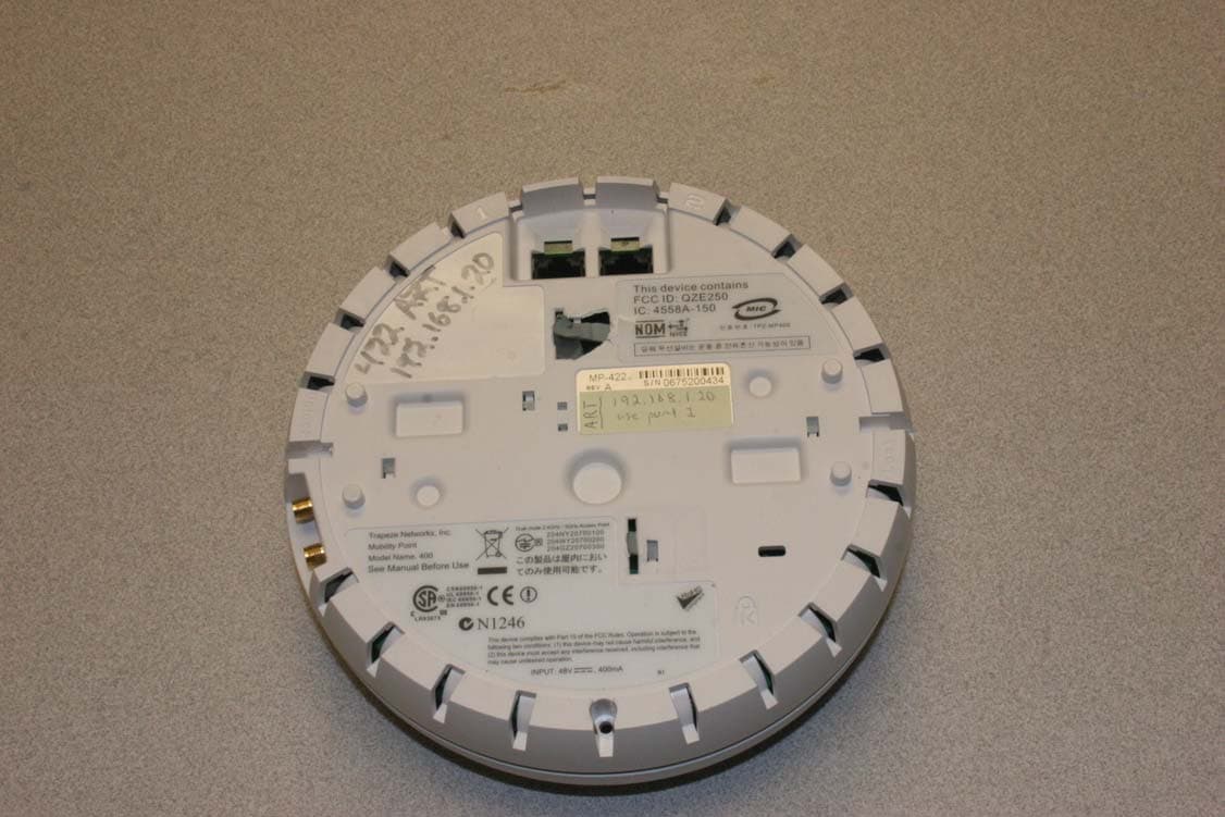
RVW2332
Sep 11, 2007802.11 A/B/G Access Point
Equipment Class
DTS - Digital Transmission System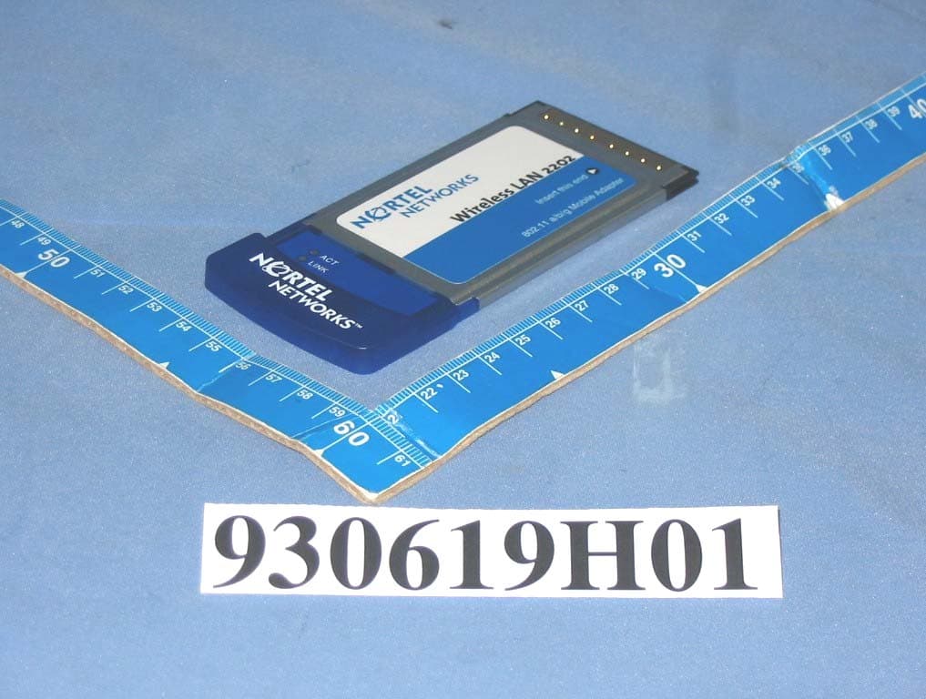
RVW2202ABG
Dec 06, 2004Nortel Networks WLAN-Mobile Adapter 2202
Equipment Class
DTS - Digital Transmission System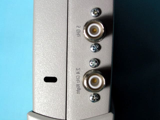
RVW2230W
Jun 19, 2004802.11 Dual Band Access Point
Equipment Class
NII - Unlicensed National Information Infrastructure TX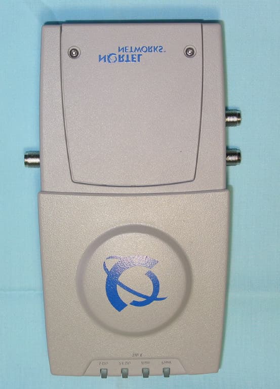
RVW2230
Mar 25, 2004802.11 Dual Band Access Point
Equipment Class
NII - Unlicensed National Information Infrastructure TX
RVW2231
Mar 25, 20042.4 GHz 802.11 Access Point
Equipment Class
DTS - Digital Transmission System