RVW2332802.11 A/B/G Access Point
Nortel Networks, Inc.
Click to zoom
Application Details
- Equipment Class
- DTS - Digital Transmission System
- Date of Grant
- Sep 11, 2007
- Application Purpose
- Original Equipment
- Date of Application
- Sep 03, 2007
- Equipment Note
- 802.11 A/B/G Access Point
- Frequency Range
- 5745.00000000 - 5825.00000000
- Company
- Nortel Networks, Inc.
- Country
- United States
Documents & Files
Document Text
Text extracted from the exhibit documents filed with the FCC. Open a document above to read the original.
Users Manual
Part No. NN47250-307 (324136-A) July 2007 4655 Great America Parkway Santa Clara, CA 95054 324136-A Nortel WLAN Access Point 2332 Series Installation Guide 2 NN47250-307 (324136-A Version 01.02) Copyright © 2007 Nortel Networks. All rights reserved. The information in this document is subject to change without notice. The statements, configurations, technical data, and recommendations in this document are believed to be accurate and reliable, but are presented without express or implied warranty. Users must take full responsibility for their applications of any products specified in this document. The information in this document is proprietary to Nortel Networks. Trademarks *Nortel Networks, the Nortel Networks logo, and the Globemark are trademarks of Nortel Networks. *Microsoft, MS, MS-DOS, Windows, and Windows NT are registered trademarks of Microsoft Corporation. *Adobe and Acrobat Reader are trademarks of Adobe Systems Incorporated. All other trademarks and registered trademarks are the property of their respective owners. Restricted rights legend Use, duplication, or disclosure by the United States Government is subject to restrictions as set forth in subparagraph (c)(1)(ii) of the Rights in Technical Data and Computer Software clause at DFARS 252.227-7013. Notwithstanding any other license agreement that may pertain to, or accompany the delivery of, this computer software, the rights of the United States Government regarding its use, reproduction, and disclosure are as set forth in the Commercial Computer Software-Restricted Rights clause at FAR 52.227-19. Statement of conditions In the interest of improving internal design, operational function, and/or reliability, Nortel Networks. reserves the right to make changes to the products described in this document without notice. Nortel Networks does not assume any liability that may occur due to the use or application of the product(s) or circuit layout(s) described herein. Portions of the code in this software product may be Copyright © 1988, Regents of the University of California. All rights reserved. Redistribution and use in source and binary forms of such portions are permitted, provided that the above copyright notice and this paragraph are duplicated in all such forms and that any documentation, advertising materials, and other materials related to such distribution and use acknowledge that such portions of the software were developed by the University of California, Berkeley. The name of the University may not be used to endorse or promote products derived from such portions of the software without specific prior written permission. SUCH PORTIONS OF THE SOFTWARE ARE PROVIDED “AS IS” AND WITHOUT ANY EXPRESS OR IMPLIED WARRANTIES, INCLUDING, WITHOUT LIMITATION, THE IMPLIED WARRANTIES OF MERCHANTABILITY AND FITNESS FOR A PARTICULAR PURPOSE. 3 Nortel WLAN Access Point 2332 Series Installation Guide In addition, the program and information contained herein are licensed only pursuant to a license agreement that contains restrictions on use and disclosure (that may incorporate by reference certain limitations and notices imposed by third parties). Legal information This section includes the following legal information: •“Limited product warranty” on page 3 •“Nortel Networks software license agreement” on page 5 •“SSH source code statement” on page 6 •“OpenSSL project license statements” on page 6 •“Trademarks” on page 2 Limited product warranty The following sections describe the Nortel standard Product Warranty for End Users. Products WLAN—Security Switch 2300 Series WLAN—Access Points 2332 Series Nortel WLAN Location Engine 2340 Limited warranty Nortel standard warranty for hardware is one (1) year. Nortel warrants software materials to be defect free for 90 Days from time of purchase. Nortel requires purchasing the software subscription if a customer would like to receive new WLAN—Security Switch 2300 Series, Nortel WLAN — Management System software. This limited warranty extends only to you the original purchaser of the Product. Exclusive remedy Your sole remedy under the limited warranty described above is, at Nortel’s sole option and expense, the repair or replacement of the non-conforming Product or refund of the purchase price of the non-conforming Products. Nortel’s obligation under this limited warranty is subject to compliance with Nortel’s then-current Return Material Authorization (“RMA”) procedures. All replaced Products will become the property of Nortel. Exchange Products not returned to Nortel will be invoiced at full Product list prices. Replacement Products may be new, reconditioned or contain refurbished materials. In connection with any warranty services hereunder, Nortel may in its sole discretion modify the Product at no cost to you to improve its reli- ability or performance. Warranty claim procedures Should a Product fail to conform to the limited warranty during the applicable warranty period as described above, Nortel must be notified during the applicable warranty period in order to have any obligation under the limited warranty. 4 NN47250-307 (324136-A Version 01.02) The End Customer or their designated reseller must obtain a Return Material Authorization number (RMA number) from Nortel for the non-conforming Product and the non-conforming Product must be returned to Nortel according to the then-current RMA procedures. The End Customer or their designated reseller is responsible to ensure that the shipments are insured, with the transportation charges prepaid and that the RMA number is clearly marked on the outside of the package. Nortel will not accept collect shipments or those returned without an RMA number clearly visible on the outside of the package. Exclusions and Restrictions Nortel shall not be responsible for any software, firmware, information or memory data contained in, stored on or integrated with any Product returned to Nortel pursuant to any warranty or repair. Upon return of repaired or…
Text truncated - open the document above for the full version.
Users Manual
90External Antennas NN47250-307 (324136-A Version 01.02) 9Directional Yagi Antenna Nortel Order Number: DR4000077E6 ❥Cushcraft Model PC2415NA36RSM ❥2.4 - 2.5 GHz, 14.1 dBi Peak Gain ❥Articulating mount for precise direction pointing ❥Good for long and narrow zones like tunnels ❥3-foot cable ❥Measures 26.5” x 3.75” x 1.5” External Antennas91 Nortel WLAN Access Point 2332 Series Installation Guide 92External Antennas NN47250-307 (324136-A Version 01.02) External Antennas93 Nortel WLAN Access Point 2332 Series Installation Guide 10Directional Patch Panel Antenna Nortel Order Number: DR4000087E6 ❥Cushcraft Model SR24120DN36RSM ❥2.4 - 2.5 GHz, 11 dBi Peak Gain ❥Uniform 120 degree H-plane and 14 degree E-plane pattern ❥Tilt-mount available for precise direction pointing ❥Designed for long, wide coverage environments ❥3-foot cable ❥Measures 23" x 3" x 2" 94External Antennas NN47250-307 (324136-A Version 01.02) External Antennas95 Nortel WLAN Access Point 2332 Series Installation Guide 96External Antennas NN47250-307 (324136-A Version 01.02) 11Directional Patch Panel Antenna Nortel Order Number: DR4000086E6 ❥Cushcraft Model S241290PN36RSM ❥2.4 - 2.5 GHz, 12 dBi Peak Gain ❥Uniform 90 degree H-plane and 17 degree E-plane pattern ❥Tilt-mount available for precise direction pointing(shown) ❥Designed for long, wide coverage environments ❥3-foot cable ❥Measures 26" x 3" x 1" External Antennas97 Nortel WLAN Access Point 2332 Series Installation Guide Horizontal Polarization BW = 90 Deg 98External Antennas NN47250-307 (324136-A Version 01.02) External Antennas99 Nortel WLAN Access Point 2332 Series Installation Guide 2.4/5.0 GHz Dual antenna 12Dual-band, Tri-mode 802.11a/b/g Spatial Diversity Antenna Nortel Order Number: DR4000078E6 ❥Cushcraft Model S24493DSN36RSM ❥2.4 - 2.5 GHz, 3.0 dBi Peak Gain ❥4.90 - 5.15 GHz, 4.0 dBi Peak Gain ❥5.15 - 5.25 GHz, 3.9 dBi Peak Gain 5.25 - 5.35 GHz, 3.2 dBi Peak Gain 5.470 - 5.725 GHz, 2.9 dBi Peak Gain 5.725 - 5.85 GHz, 2.6 dBi Peak Gain ❥Each antenna port can be used individually for simultaneous 802.11a and 802.11b/g ❥Well-suited for high data rate office applications ❥3-foot cable ❥Measures 6.16” x .89” x 3.66” 100External Antennas NN47250-307 (324136-A Version 01.02) Azimuth Pattern for 2.4 GHz External Antennas101 Nortel WLAN Access Point 2332 Series Installation Guide Elevation Pattern 1 for 2.4 GHz 102External Antennas NN47250-307 (324136-A Version 01.02) Elevation Pattern 2 for 2.4 GHz External Antennas103 Nortel WLAN Access Point 2332 Series Installation Guide Azimuth Pattern for 5.0 GHz 104External Antennas NN47250-307 (324136-A Version 01.02) Elevation Pattern 1 for 5.0 GHz External Antennas105 Nortel WLAN Access Point 2332 Series Installation Guide Elevation Pattern 2 for 5.0 GHz 106External Antennas NN47250-307 (324136-A Version 01.02) Glossary of common antenna terminology The following glossary includes basic antenna terminology that can help in the selection and/or recommendation of a particular antenna. These terms are used throughout the remainder of the document: Omnidirectional (Omni) – Refers to the antenna coverage pattern. An omnidirectional antenna creates a uniform coverage pattern. Most omnidirectional antennas are weakest directly above and directly below their endpoints – this characteristic creates the familiar dual-lobe pattern shown on the E-plane graphs. Nulls are typically related to the orien- tation of the dipole/monopole antenna relative to the horizontal or vertical planes. The lobes grow and shrink depending upon the ground plane effects and cancellation/addition of the radiating signal. Omnidirectional antennas are suitable for most general deployments. Directional – Refers to the antenna coverage pattern. A directional antenna focuses its lobe or radiated energy in a particular direction. In general, as the gain of a directional antenna increases, the radiating beamwidth or lobe decreases. This design increases the transmitted power and communication distance in a specific direction at the expense of uniform coverage, as compared to an omnidirectional antenna. A directional antenna must be “aimed” at the intended coverage zone. Gain – Expressed in dBi, indicates the relative increase in radiated power over an isotropic point radiating source with a reference gain of 1.0. Each 3 dB increment in power effectively doubles the radiated energy. For example, an antenna with a gain of 9 dBi increases the transmit power 8 times more than an isotropic point radiating source. For example: 12.5 mW = 11 dBm 11 dBm + 9dBi = 20 dBm 20 dBm = 100 mW 100mw/12.5 mW = 8 times more power E-Plane graph – The elevation plane graph shows the radiated antenna coverage pattern as a vertical cross section - as if looking directly at the antenna from the side. H-Plane graph – The horizontal plane graph shows the radiated antenna coverage pattern as a horizontal cross section - as if looking directly at the antenna from above. 107 Nortel WLAN Access Point 2332 Series Installation Guide AP troubleshooting After you insert the Cat-5 cable into an AP’s port connector and enable PoE on the cable, observe the device’s health or LINK LED to determine the status of the connection with the WSS. •If the LED is green and is glowing steadily, the AP was booted successfully by the WSS and is ready for operation. •If the LED is not steadily glowing green, see Tab l e 5. (For descriptions of all the LEDs, see “Status LEDs” on page 28.) Table 5: Health LED States (2332 Series) Health or LINK LED Appearance DiagnosisRemedy Not solid greenAP radio needs to be enabled.Enable at least one of the radios. If the LED is still not solid green, try the remedy listed in this table based on the LED’s appearance. UnlitAP is not receiving power.Check the Cat-5 cable connection(s). For a direct connection to a WSS: •Set the port type on the WSS to an AP port. •Verify that Power over Ethernet (PoE) is enabled on the WSS port connected to the AP. For an indirect connection through the …
Text truncated - open the document above for the full version.
Cover Letter(s)
4655 Great America Parkway Santa Clara, CA, 95054 To: Federal Communications Commission 7435 Oakland Mills Road Columbia, Maryland 21046 Subject: Authorization of David Waitt to act on our behalf and as our agent for preparation of FCC and IC certification applications. Gentlemen, This is a letter of authorization to accept David Waitt, an independent consultant who’s services have been retained by Nortel to sign applications before the commission on our behalf, to make representations to you on our behalf and to receive and exchange data between our company and the Commission. Under FCC Docket number 20780 and General Docket Number 80-284 pursuant to Part 15 of the FCC Rules and Regulations. If you have any further questions or need additional information, please feel free to contact me at [email protected] June 2007 Tim Blaney Nortel
Cover Letter(s)
To: Federal Communications Commission 7435 Oakland Mills Road Columbia, Maryland 21046 Subject: Confidentiality Request for Certification Application Gentlemen, On behalf of Nortel Networks Inc., I request that the following documents: • Any/All circuit schematics. • Any/All electrical block diagrams • Operational Descriptions Associated with the following Part 15 Certification applications (FCC ID): RVW2332 be withheld from public disclosure per Section 0.459 of the FCC Rules. This request is made under the provisions of Section 0.457(d) of the FCC rules and Sections 552(b)(4) of the Freedom of information Act. These Sections authorize withholding from public inspection, materials which would be privileged as a matter of law if retained by the person submitting them in addition to materials, which would not customarily be released to the public, by that person. If you have any questions, please do not hesitate to contact me at: [email protected] or (408) 832-7053 Sincerely, David Waitt Consultant representing Nortel
Cover Letter(s)
4 Sept 2007 To: Federal Communications Commission Industrie Canada From: Nortel Networks Subject: Professional Installation and Configuration FCC ID: RVW2332 IC: 332R-2332 Gentlemen, The purpose of this letter is to address concerns regarding the professional installation of the 2332 series access point radios. The Norte series 2332 access point radio is part of a enterprise based 802.11 network infrastructure solution. The unit is power by POE and is controlled by a “smart switch”. This switch handles such things as power control, “hand-offs” form one AP to another (as a client roams throughout the network), load balancing, channel selection and other aspects of network operation. The system is only sold to enterprise customers and is not sold, marketed to, or recommended for individual or non-enterprise use. Compliance with FCC Part 15.15 FCC Part 15.15(b) states: “An intentional or unintentional radiator must be constructed such that the adjustments of any control that is readily accessible by or intended to be accessible to the user will not cause operation of the device in violation of the regulations.” Compliance with Part 15.15 will be accomplished by a professional, trained configuring the access-points correctly during the installation. Professional installation and configuration of the devices is required due to the complexity of a typical installation. A typical installation may consist of several dozen access points installed throughout a corporate building or campus. Installation, configuration and testing of the system are not trivial tasks and must be performed by trained professionals. The configuration settings of the access point are password protected to eliminate the possibility of unauthorized personnel altering the configuration and thus disrupting the proper performance of the network, therefore the end user of the network will not have access to the configuration of the access points. There is no specific mention of professional installation within the user guide given the customers for a system. Installation is usually carried out by either a professional IT department (who has received training form Nortel on how to conduct site surveys and install the system) or the installation is performed by a Nortel field service group. If there is any additional information required, please contact me at the email address below David Waitt Consultant Representing Nortel [email protected]
ID Label/Location Info
NOTES: 1. Material - 8B35(0.254 mm) or equivalent 2. Adhesive - 3M 7533 or equivalent 3. Background - white 4. All graphic and text color - Black 5. Graphic and text location tolerance + -0.3mm 6. Pressing tolerance + -0.15 mm 8. Pressing burr downward (the adhesive face) Nortel AP2332-A1 NP REGIONAL V.01 970010000766G Background-white Graphic& text-black MODEL:2332-A1 Order No. DR4001086E6 70.28 R 59.00 1.78 25.43 8B35 0.254t Jane 2007/08/16 Ping 2007/08/16 FCC ID RVW2332 IC ID 332R-2332 Regulatory Label location Model Number Label
RF Exposure Info
Mobile Power Density Calculation for FCC ID: RVW2332 IC: 332R-2332 The Access Point (AP) is an IEE802.11 A / B /G radio. The access point operates on the 2.4 GHz and 5 GHz ISM and 5GHz UNII bands. Operating Environment: The operating environment for the for the radio in all cases is a fixed, uncontrolled environment, however, the devices are classified as being “Mobile”, Therefore the exposure at 20 cm is calculated. Fixed, Uncontrolled Environment: The FCC limit for the power density for uncontrolled exposure to RF devices operation at 2.4GHz and 5GHz at a distance of 20 cm is: 1 mW/cm 2 Power density is calculated from the following equation Exposure (mW/cm 2 ) = EIRP(mW) * Duty Cycle 4*PI* Radius 2 (cm) Where: Radius = 20 cm Duty Cycle = assumed to be 100% to yield a worst case result. The maximum allowed external antenna gain on 2.4 GHz is 13dBi The maximum allowed external antenna gain on 5 GHz is 14dBi (with some power reduction in the UNII bands) 2.4GHz ISM Band MPE distance Calculation Using the highest EIRP (all settings / all antenna) measured on the 2.4 GHz ISM band. MAX Pout: 20.00dBm, 100 mW MAX Ant Gain 14.3 dBi (26.91x) EIRP: 34.3 dBm (2691.534 mW EIRP MAX) 5GHz Band MPE distance Calculation Using the highest EIRP (all settings / all antenna) on the 5 GHz (ISM) band. MAX Pout: 12.77 dBm , 18.92 mW MAX Ant Gain 16.1 dBi (40.73x) EIRP: 28.87 dBm (770.903 mW EIRP MAX) Total EIRP (mw) 2691.534+770.903 = 3462.437 mW EIRP total Calculating power density at a distance of 20 cm yields: Delta = specification - result 1 mW/cm 2 - .6888 mw/cm 2 = .3111 mw/cm 2 = -1.619 dB below limit 3462.437 5026.548 3462.437 * 1 4 * Pi * 20 2 Power = Density .6888 mw/cm 2
Test Report
Page 1 of 77 EMI Test Report on IEEE 802.11 Access Point. Series: 2332 Model: 2332-A1 FCC ID: RVW2332 IC ID: 332R-2332 Report:NOR2332 FCC Part 15.247 Certification Application Industrie Canada RSS210 Certification Application Prepared by: David Waitt 21565 Mary Alice Way Los Gatos,CA [email protected] (408) 832 7053 FCC Part 15 / IC RSS-210 Certification Application Page 2 of 77 Table of Contents Section Page General Information ........................................................................................................................................................ 4 Detailed Product Information ......................................................................................................................................... 5 Internal Antennas........................................................................................................................................................... 6 Test Results Summary.................................................................................................................................................... 7 Test Facilities ................................................................................................................................................................... 8 Equipment Lists............................................................................................................................................................... 9 Instrument Calibration.................................................................................................................................................... 9 Elliott Test Equipment (Test Dates 19 April - 24 May 2007) ......................................................................................... 9 Test Methods ................................................................................................................................................................. 10 Test Results ................................................................................................................................................................... 11 802.11 B/G/A Maximum RF Power Output at Antenna Terminals .............................................................................. 12 Specifications:........................................................................................................................................................................................................12 Procedure: .............................................................................................................................................................................................................12 Results: ..................................................................................................................................................................................................................12 Channel 1, 802.11 B, Power setting 21 ....................................................................................................................... 13 Channel 6, 802.11 B, Power setting 21 ....................................................................................................................... 13 Channel 11, 802.11 B, Power setting 21 ..................................................................................................................... 14 Channel 1, 802.11 G, Power setting 21....................................................................................................................... 14 Channel 6, 802.11 G, Power setting 21....................................................................................................................... 15 Channel 11, 802.11 G, Power setting 21..................................................................................................................... 15 5745MHz , 802.11 A, Power setting 21 ...................................................................................................................... 16 5785MHz , 802.11 A, Power setting 21 ...................................................................................................................... 16 5825 MHz , 802.11 A, Power setting 21 ..................................................................................................................... 17 6 dB and 99% Bandwidth ............................................................................................................................................ 18 Specifications.........................................................................................................................................................................................................18 Procedure: .............................................................................................................................................................................................................18 Results: ..................................................................................................................................................................................................................18 Power Spectral Density ............................................................................................................................................... 25 Specifications:........................................................................................................................................................................................................25 Procedure: .............................................................................................................................................................................................................25 Results: ....................................................................................................................................................................................…
Text truncated - open the document above for the full version.
Contact Information
Applicant
Claudio Morfe(Assistant Secretary)
Technical Contact
Elliott LabsDavid Waitt
[email protected]408-832-7053
21565 Mary Alice Way · Los Gatos, California · United States
Test Firm
Elliott Laboratories LLCDavid Bare
Technical Specifications
| # | Rule Parts | Frequency Range | Power Output |
|---|---|---|---|
| 2 | 15C | 5.75 GHz - 5.83 GHz | 19.00 mW |
Other Applications from Nortel Networks, Inc.
RVW2330
Sep 27, 2005Dual Band Access Point
Equipment Class
DTS - Digital Transmission System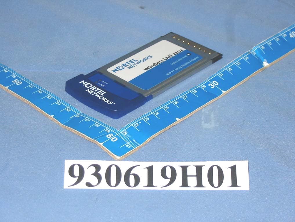
RVW2202ABG
Dec 06, 2004Nortel Networks WLAN-Mobile Adapter 2202
Equipment Class
DTS - Digital Transmission System
RVW2230W
Jun 19, 2004802.11 Dual Band Access Point
Equipment Class
NII - Unlicensed National Information Infrastructure TX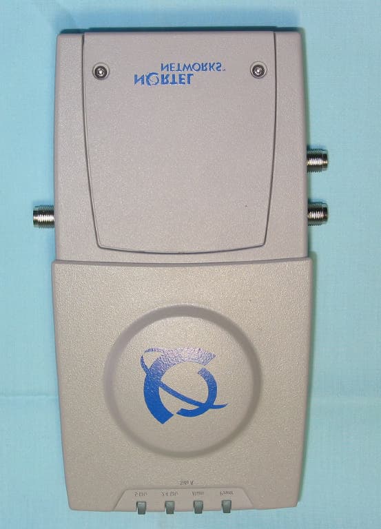
RVW2230
Mar 25, 2004802.11 Dual Band Access Point
Equipment Class
NII - Unlicensed National Information Infrastructure TX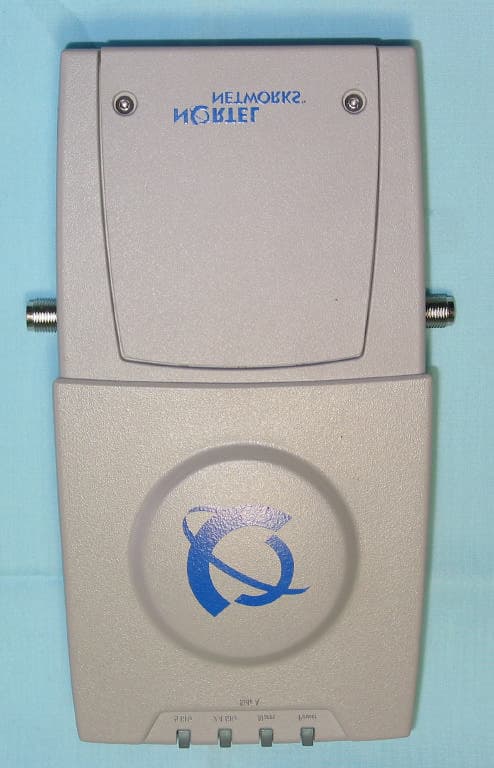
RVW2231
Mar 25, 20042.4 GHz 802.11 Access Point
Equipment Class
DTS - Digital Transmission System