RVW2230W802.11 Dual Band Access Point
Nortel Networks, Inc.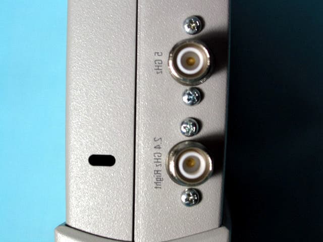
Click to zoom
Application Details
- Equipment Class
- NII - Unlicensed National Information Infrastructure TX
- Date of Grant
- Jun 19, 2004
- Application Purpose
- Original Equipment
- Date of Application
- Jun 19, 2004
- Equipment Note
- 802.11 Dual Band Access Point
- Frequency Range
- 5745.00000000 - 5805.00000000
- Company
- Nortel Networks, Inc.
- Country
- United States
Documents & Files
Document Text
Text extracted from the exhibit documents filed with the FCC. Open a document above to read the original.
Cover Letter(s)
To: Mr. Tim Johnson, American TCB From: David Waitt Subject: FCC ID RVW2230 compliance with FCC Part 15.407 (c),(d),(e),(g) Date: 8 June 2004 This letter attests to the compliance of the access point radio to the above referenced FCC specification. If there are any questions or if additional information is required, please contact me at [email protected] On behalf of Nortel Networks David Waitt 15.407 (c) The device shall automatically discontinue transmission in case of either absence of information to transmit or operational failure. These provisions are not intended to preclude the transmission of control or signaling information or the use of repetitive codes used by certain digital technologies to complete frame or burst intervals. Applicants shall include in their application for equipment authorization a description of how this requirement is met. Data transmission is always initiated by software, which is then pass down through the MAC, through the digital and analog baseband, and finally to the RF chip. Several special packets (ACKs, CTS, PSPoll, etc...) are initiated by the MAC. There are the only ways the digital baseband portion will turn on the RF transmitter, which it then turns off at the end of the packet. Therefore, the transmitter will be on only while one of the aforementioned packets are being transmitted. In addition, the product incorporates a watchdog timer. If the radio were to “lock up” the timer would reboot the radio where it would come up in the receive mode. 15.407(d) Any U-NII device that operates in the 5.15-5.25 GHz band shall use a transmitting antenna that is an integral part of the device. If an external antenna is used with the device, it will be permanently attached to the radio using a method approved by the FCC, thus meeting the “integral” antenna requirements. Once the external antenna is connected to the access point, it will not be able to be removed. Additionally, the external antenna will be professionally installed. In this case “Professional Installations may be performed by either an outside contracted IT company or the IT department (also approved / trained by the Grantee) responsible for the location where the wireless network is installed. The installer must have been instructed by the grantee and must be capable of making the “permanent” antenna connection. 15.407(e) Within the 5.15-5.25 GHz band, U-NII devices will be restricted to indoor operations to reduce any potential for harmful interference to co-channel MSS operations. The access point is not intended for outdoor use. The manual includes a statement stating that outdoor use is not allowed. Additionally, the enclosure of the access point is not weatherproof. 15.407(g) Manufacturers of U-NII devices are responsible for ensuring frequency stability such that an emission is maintained within the band of operation under all conditions of normal operation as specified in the users manual. The transmit frequency of the access point has been monitored while the device has been temperature cycled over its specified operating temperature range. Concurrently, the supply voltage was varied throughout its specified operating range. In all cases, no portion of the transmitted signal ( within the 26 dB BW ) of the device drifted out of band.
Cover Letter(s)
To: Federal Communications Commission Industrie Canada From: Nortel Networks Subject: Justification for Class A classification of the following FCC IDs FCC ID: RVW2230W IC: 332R-2230W Date: 8 June 2004 Gentlemen, The purpose of this letter is to provide justification for classifying the above products as Class A. The Nortel Models 2230 and 2230INT products are intended only for industrial / corporate environments. Marketing of the products will not be targeted at individuals for residential use. The 2230 and 2231 will not be available for purchase at consumer oriented retail outlets. If any further information is required, please do not hesitate to contact me at the email address below. David Waitt Consultant representing Nortel [email protected]
Cover Letter(s)
To: Federal Communications Commission 7435 Oakland Mills Road Columbia, Maryland 21046 Subject: Confidentiality Request for Certification Application Gentlemen, On behalf of Nortel Networks Inc., I request that the following documents: • Any/All circuit schematics. • Any/All electrical block diagrams Associated with the following Part 15 Certification applications (FCC ID): RVW2230W be withheld from public disclosure per Section 0.459 of the FCC Rules. This request is made under the provisions of Section 0.457(d) of the FCC rules and Sections 552(b)(4) of the Freedom of information Act. These Sections authorize withholding from public inspection, materials which would be privileged as a matter of law if retained by the person submitting them in addition to materials, which would not customarily be released to the public, by that person. If you have any questions, please do not hesitate to contact me at: [email protected] or (408) 832-7053 Sincerely, David Waitt Consultant representing Nortel Networks
External Photos
4655 Great America Parkway Santa Clara, California 95054 www.nortelnetworks.com External Product Photos IEEE 802.11 Access Point. FCC Part 15 Certification Application Prepared by: David Waitt 202 Calvert Drive #217 Cupertino, Ca. 95014 [email protected] (408) 832 7053 Nortel Networks Access point, Model 2230 & 2230 INT Side 1 Nortel Networks Access point, Model 2230 & 2230 INT Side 2 Nortel Networks Access point, Model 2230 & 2230 INT Side L & R Nortel Networks Access point, Model 2230 & 2230 INT Connector Detail Note that on the 2230INT model, these connectors have NO internal connection to the circuit boards
ID Label/Location Info
RVW2230W332R-2230W RVW2230W332R-2230W Complies with FCC Par t 15 and Canadian ICES-003. See manual bef ore use. 5GHz FOR INDOOR USE ONLY P a ge of Da te: P a ge of Da te: C ompa ny : Inv : A ttn: Des c : BAY AREA LABELS ̈ 200% F O R C L AR IT Y 2 -98 1s t P roof Complies with FCC Par t 15 and Canadian ICES-003. See manual bef ore use. 5GHz FOR INDOOR USE ONLY
ID Label/Location Info
4655 Great America Parkway Santa Clara, California 95054 www.nortelnetworks.com To: Office of Engineering and Technology Federal Communications Commission 445 12TH ST SW Washington DC 20554 Re: FCC ID: RVW2230W and RVW2230WINT IC: 332R-2230W and 332R-2230WINT Regulatory Compliance Label Placement Gentlemen, The regulatory label containing the FCC and IC ID of the access point radios specified above and will be located on the bottom of the unit as shown. FCC & IC Regulatory Label Here
Internal Photos
Internal Product Photos IEEE 802.11 A/B/G Access Point. FCC Part 15 Certification Application IC RSS-210 Certification Application Prepared by: David Waitt 202 Calvert Drive #217 Cupertino, Ca. 95014 [email protected] (408) 832 7053 Access point Radio, Internal Side 1 Internal Antenna Detail Access Point, Internal Side 2 Access Point, Internal Side 2, Shields Removed RF Circuit Detail
Operational Description
WLAN Access Port 2230 & 2231 Features & Benefits Nortel Networks WLAN Access Ports 2230 and 2231 work together with Nortel Networks WLAN Security Switch 2270 to provide: FLEXIBILITY Dynamic Load Balancing - across multiple WLAN Access Ports to enhance the end-user satisfaction and optimize the WLAN network performance even under stress. This is done automatically to minimize the network maintenance and increase the network responsiveness. Quality of Service for WLAN - ensures a minimum delay. When using multimedia applications, maintaining this delay near a constant value (i.e. minimum jitter), and prioritizing traffic for better performance is essential. It has been fully tested and optimized to support Nortel Networks WLAN Handsets 2210 and 2111. SECURITY Unauthorized access point "containment" - prevents users from associating with unauthorized access points even if they are not physically connected to the LAN. This feature can also be deployed as a protective shield against wireless intruders in environments where WLAN access is not desirable. Unauthorized access point location - so that appropriate measures can be taken quickly. MANAGEMENT Auto-discovery and auto-configuration - once plugged to the LAN, Nortel Networks WLAN Access Ports are capable of finding the WLAN Security Switch 2270 they should associate to. Thus they automatically download their configuration (channel, RF power...) and discover the other Access Ports present in the WLAN network. Real time dynamic coverage - thanks to the continuous RF information monitored by the WLAN Access Ports 2230 and 2231, the WLAN Security Switch 2270 makes real time decisions to optimize the RF coverage. It prevents interferences by assigning the right channels to the WLAN Access Ports. It also detects and corrects any coverage hole appearing in the network, adjusting the RF power of each Access Port. As a result, the WLAN network always has optimum resource allocation and high quality for the end-user as it adapts in real time to the new environmental constraints. Automatic firmware synchronization - when new firmware is downloaded on the WLAN - Security Switch 2270, the WLAN Access Ports automatically detect it and proceed to the firmware upgrade thus saving maintenance time and cost but also ensuring that the latest improvements are available in the WLAN network. Site Survey Tool Nortel Networks WLAN Site Survey Tool is a comprehensive tool for customers who want to fine tune before their WLAN network deployment. Location Services Software Nortel Networks WLAN Location Services Software provides highly accurate location information (to less than 10 meters). This is useful for E911 emergency call location, unauthorized access point detection and tracking devices in very mobile environments such as healthcare, warehouses or for inventory management.
RF Exposure Info
Mobile Power Density Calculation for FCC ID: RVW223W IC: 332R-2230W The Access Point (AP) is an IEE802.11 A / B /G radio. The access point operates on the 2.4 GHz and 5 GHz ISM bands. Operating Environment: The operating environment for the for the radio in all cases is a fixed, uncontrolled environment, however, the devices are classified as being “Mobile”, Therefore the exposure at 20 cm is calculated. Fixed, Uncontrolled Environment: The FCC limit for the power density for uncontrolled exposure to RF devices operation at 2.4GHz and 5GHz at a distance of 20 cm is: 1 mW/cm 2 Power density is calculated from the following equation Exposure (mW/cm 2 ) = EIRP(mW) * Duty Cycle 4*PI* Radius 2 (cm) Where: Radius = 20 cm Duty Cycle = assumed to be 100% to yield a worst case result. The maximum allowed external antenna gain on 2.4 GHz is 6.8dBi The maximum allowed external antenna gain on 5 GHz is 7.4dBi 2.4GHz ISM Band MPE distance Calculation Using the highest power measured on the 2.4 GHz ISM band. MAX Pout: 18.97dBm (78.89 mW) MAX Ant Gain 7.8 dBi (6.02x) EIRP: 26.77 dBm (475.33 mW EIRP) 5GHz Band MPE distance Calculation Using the highest power measured on the 5 GHz band. MAX Pout: 17.81 dBm (60.39 mW) MAX Ant Gain 10.4 dBi (10.96x) EIRP: 28.3 dBm (662.21 mW EIRP) Total EIRP (mw) 475.33 + 662.21 = 1137.55 Calculating power density at a distance of 20 cm yields: Delta = specification - result 1 mW/cm 2 - .2263 mw/cm 2 = .7736 mw/cm 2 = -6.453 dB below limit 1137.55 5026.54 1137.55 * 1 4 * Pi * 20 2 Power = Density .2263 mw/cm 2
Test Report
Supplemental “Dual Xmit” Test Report on the Dual Band 802.11 Access Point FCC ID: RVW2230W IC: 332R-2230W FCC Part 15, Subpart E, UNII (Part 15.401) Certification Application Industrie Canada RSS-210 Certification Application Prepared by: David Waitt 202 Calvert Drive #217 Cupertino, Ca. 95014 [email protected] (408) 832 7053 Part 15 / RSS-210 Certification application Page 2 of 7 Table of Contents Section Page General Information ....................................................................................................................3 Test Methods..............................................................................................................................3 Test Facilities..............................................................................................................................3 Equipment Lists ..........................................................................................................................4 Instrument Calibration .............................................................................................................4 Elliott Test Equipment..............................................................................................................4 Dual Xmit, Radiated Emissions in Restricted bands ...................................................................5 Specifications: .........................................................................................................................5 Procedure: ...............................................................................................................................5 Dual Xmit Radiated Emissions Test Setup ..............................................................................6 Dual Xmit Radiated Emissions Test Results............................................................................7 Part 15 / RSS-210 Certification application Page 3 of 7 General Information Per a request of the FCC, the access point radio was tested for radiated emissions in restricted bands while transmitting on both 2.4 GHz and 5 GHz at simultaneously. The test was conducted at Elliott Labs in Sunnyvale California, Chamber #5 on 17 May 2004 Test Methods The access point was tested for out of band radiated emissions with the unit transmitting on 802.11 B, 2437 MHz and 802.11 A on 5290 MHz. These frequencies and power levels were chosen because these frequencies produced the worst case radiated emissions during the radiated emissions in restricted bands test performed previously. The unit was set to transmit at the same power level as was used in the initial radiated emissions tests and was transmitting at the maximum data rate. Test Facilities The certification tests were performed at: Elliott Labs 684 West Maude Ave Sunnyvale, CA 94086 General: Final radiated test measurements were taken in May 2004 at the Elliott Laboratories Chamber #5 in Fremont CA.. The test site contains separate areas for radiated and conducted emissions testing. Pursuant to section 2.948 of the Rules, construction, calibration, and equipment data has been filed with the Commission. The FCC recommends that ambient noise at the test site be at least 6 dB below the allowable limits. Ambient levels are below this requirement with the exception of predictable local TV, radio, and mobile communications traffic. The test site contains separate areas for radiated and conducted emissions testing. Considerable engineering effort has been expended to ensure that the facilities conform to all pertinent FCC requirements. Antenna, Antenna Mast and Turntable The Horn antennas that are use to measure radiated emissions above 1000MHz are amounted on a non-conductive antenna mast equipped with a motor drive to vary the antenna height. ANSI C63.4 specifies that the test height above the ground plane shall be 80cm unless the equipment is intended to be floor mounted. During the radiated emissions tests the equipment is positioned on a motorized turntable in conformance with the ANSI requirement. Part 15 / RSS-210 Certification application Page 4 of 7 Equipment Lists Instrument Calibration All test equipment is regularly checked to ensure that performance is maintained in accordance with the manufacturer's specifications. All antennas are calibrated at regular intervals with respect to tuned half-wave dipoles. An exhibit of this report contains the list of test equipment used and calibration information. Elliott Test Equipment The following test equipment was used to perform the testing Manufacturer Description Model # Asset # Cal Due Hewlett Packard Microwave Preamplifier, 1-26.5GHz 8449B 263 09-Jan-05 EMCO Horn Antenna, D. Ridge 1-18GHz 3115 868 20-Apr-06 Hewlett Packard Microwave EMI test system (SA40, 9kHz - 40GHz) Fremont 84125C 1410 26-Mar-05 Hewlett Packard EMC Spectrum Analyzer 9KHz-26.5GHz, non programmable 8563E 284 15-Mar-05 Rohde & Schwarz Power Meter, Single Channel NRVS 1290 22-Apr-05 Rohde & Schwarz Peak Power Sensor 100uW - 2 Watts NRV-Z32 1536 22-Apr-05 Part 15 / RSS-210 Certification application Page 5 of 7 Dual Xmit, Radiated Emissions in Restricted bands Specifications: FCC Part 15 Paragraph 15.247(c) IC Specification: RSS-210 Procedure: This test was conducted in a 5 meter anechoic chamber at Elliott Laboratories Fremont, California facility. The unit was placed on a rotating wooden table 80cm above the ground plane. A Horn antenna was secured to a mast 3 meters away. The emissions up to 40 GHz were examined. Those emission falling within a restricted band were evaluated against the “restricted band emission limit” ( 54 dBμV / 74 dBμV). The UUT was rotated 360 degrees and the height of the antenna adjusted from 1 to 4 meters above the ground plane to determine the maximum level of the emission. The level of the emission was measured in two modes, “Peak” and “Average” using the following measurement bandwidths Restricted Band Peak Measurements: RBW & VBW: 1 MHz Restricted Band Averag…
Text truncated - open the document above for the full version.
Test Report
EMI Test Report on IEEE 802.11 Access Point. Models: 2230 & 2230INT FCC ID: RVW2230W IC ID:332R-2230W FCC Part 15, Subpart E, UNII (Part 15.401) Certification Application Industrie Canada RSS-210 Certification A pplication Prepared by: David Waitt 202 Calvert Drive #217 Cupertino, Ca. 95014 [email protected] (408) 832 7053 Part 15 / RSS-210 Certification Application Page 2 of 73 Table of Contents Section Page GENERAL INFORMATION........................................................................................................4 DETAILED PRODUCT INFORMATION / OPERATIONAL DESCRIPTION ..............................5 Internal Antenna Version ......................................................................................................................................................... 5 Internal / External Antenna Version ....................................................................................................................................... 6 REPORT ORGANIZATION AND RESULTS SUMMARY ..........................................................7 TEST FACILITIES......................................................................................................................8 EQUIPMENT LISTS ...................................................................................................................9 Instrument Calibration ............................................................................................................................................................. 9 Elliott Test Equipment .............................................................................................................................................................. 9 Additional Test Equipment ...................................................................................................................................................... 9 TEST METHODS .....................................................................................................................10 TEST RESULTS.......................................................................................................................12 802.11 A Maximum RF Power Output at Antenna Terminals............................................................................................ 13 RF Transmit Power Summary Results: ................................................................................................................................ 14 26 dB Channel Power, 5180 MHz ........................................................................................................................................ 15 26 dB Channel Power, 5240 MHz ........................................................................................................................................ 15 26 dB Channel Power, 5260 MHz ........................................................................................................................................ 16 26 dB Channel Power, 5320 MHz ........................................................................................................................................ 16 26 dB Channel Power, 5745 MHz ........................................................................................................................................ 17 26 dB Channel Power, 5765 MHz ........................................................................................................................................ 17 26 dB Channel Power, 5805 MHz ........................................................................................................................................ 18 20 dB / 26 dB bandwidth......................................................................................................................................................... 19 20 dB / 26 dB bandwidth Summary Results......................................................................................................................... 19 20 dB Bandwidth Plots ......................................................................................................................................................... 19 26 dB Bandwidth Plots ......................................................................................................................................................... 22 99% Bandwidth Plots .......................................................................................................................................................... 25 Power Spectral Density ........................................................................................................................................................... 29 Power Spectral Density Summary Results: .......................................................................................................................... 29 Power Spectral Density Plots ............................................................................................................................................... 30 Out of band Spurious Emissions ............................................................................................................................................ 33 Out of band Spurious Emissions Results Summary: ............................................................................................................ 33 UUT Transmitting on 5180MHz .......................................................................................................................................... 34 UUT Transmitting on 5260MHz .......................................................................................................................................... 36 UUT Transmitting on 5320MHz .......................................................................................................................................... 39 Part 15 / RSS-210 Certification Application Page 3 of 73 UUT Transmitting on 5745MHz ..…
Text truncated - open the document above for the full version.
Contact Information
Applicant
Claudio Morfe(Assistant Secretary)
Technical Contact
ConsultantDavid Waitt
[email protected]408-832-7053
202 Calvert Dr #217 · Cupertino, California · United States
Non-Technical Contact
ConsultantDavid Waitt
[email protected]408-832-7053
Test Firm
Elliott Laboratories LLCDavid Bare
Technical Specifications
| # | Rule Parts | Frequency Range | Power Output |
|---|---|---|---|
| 3 | 15E | 5.75 GHz - 5.80 GHz | 93.00 mW |
Other Applications from Nortel Networks, Inc.
RVW2332
Sep 11, 2007802.11 A/B/G Access Point
Equipment Class
DTS - Digital Transmission System
RVW2330
Sep 27, 2005Dual Band Access Point
Equipment Class
DTS - Digital Transmission System
RVW2202ABG
Dec 06, 2004Nortel Networks WLAN-Mobile Adapter 2202
Equipment Class
DTS - Digital Transmission System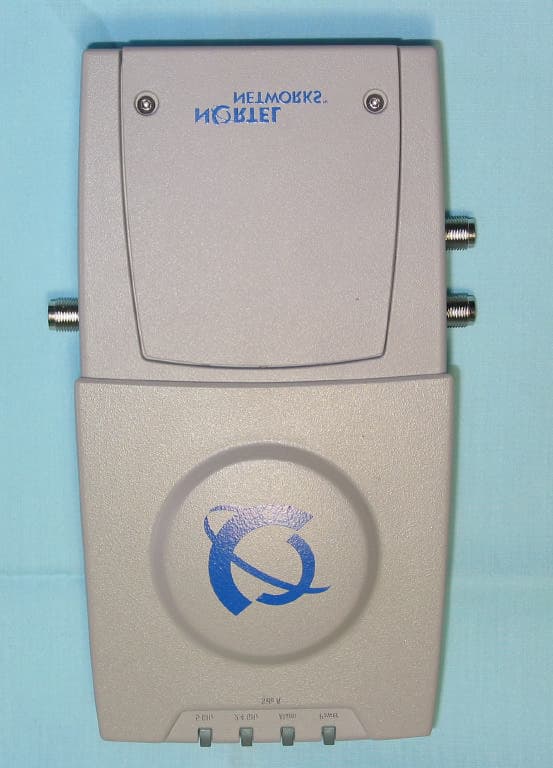
RVW2230
Mar 25, 2004802.11 Dual Band Access Point
Equipment Class
NII - Unlicensed National Information Infrastructure TX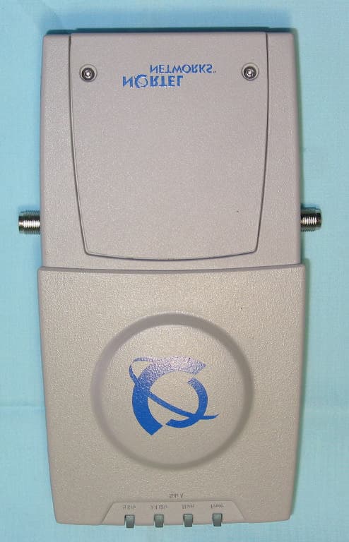
RVW2231
Mar 25, 20042.4 GHz 802.11 Access Point
Equipment Class
DTS - Digital Transmission System