RVW2230802.11 Dual Band Access Point
Nortel Networks, Inc.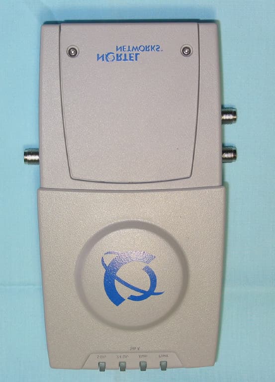
Click to zoom
Application Details
- Equipment Class
- NII - Unlicensed National Information Infrastructure TX
- Date of Grant
- Mar 25, 2004
- Application Purpose
- Original Equipment
- Date of Application
- Mar 25, 2004
- Equipment Note
- 802.11 Dual Band Access Point
- Frequency Range
- 5745.00000000 - 5805.00000000
- Company
- Nortel Networks, Inc.
- Country
- United States
Documents & Files
Document Text
Text extracted from the exhibit documents filed with the FCC. Open a document above to read the original.
Users Manual
March 16, 2004 External-Antenna Nortel Networks WLAN - Access Point Quick Installation Guide External-Antenna Nortel Networks WLAN - Access Point Quick Installation Guide System Release 2.0 This Guide contains several sections allowing you to install an AS-1200-BG-EXT or AS-1200-ABG-EXT Nortel Networks WLAN - Access Point or an AS-1200-ABG-EXT-RE Nortel Networks WLAN - Remote Edge Access Point (Remote Edge Access Point). These models contain internal 802.11a and 802.11b/g antennas and connectors for optional external 802.11a and 802.11b/g antennas. If you are installing an AS-1200-BG-INT or AS-1200-ABG-INT Nortel Networks WLAN - Access Point with internal 802.11a and 802.11b/g antennas and no connectors for optional external antennas, please refer to the Internal-Antenna Airespace Access Point Quick Installation Guide . •Overview •Step 1: Collecting Required Tools and Supplies •Step 2: Configuring the Nortel Networks WLAN - Access Point or Remote Edge Access Point Before Installation •Step 3: Preparing Mounting Locations •Step 4: Mounting the Nortel Networks WLAN - Access Points •Step 5: Returning MAC Information •Planning Notes •FCC Statements for Nortel Networks WLAN - Access Points ATTENTION!Special Considerations While Nortel Networks WLAN - Access Points have been engineered for easy installation, there are some guidelines that are very important to the end users: •PLACE Nortel Networks WLAN - Access Points NO MORE THAN 140 FEET APART FROM EACH OTHER. Placing Nortel Networks WLAN - Access Points further apart almost always results in poor coverage. •DO NOT MOUNT Nortel Networks WLAN - Access Points OUTSIDE BUILDINGS. •DO NOT MOUNT Nortel Networks WLAN - Access Points ON BUILDING PERIMETER WALLS UNLESS THE OPERATOR WANTS TO PROVIDE COVERAGE OUTSIDE THE BUILDING. •MAKE SURE that plenum-mounted Nortel Networks WLAN - Access Points and Remote Edge Access Points are powered using Power Over Ethernet (POE) to comply with safety regulations. March 16, 20042 External-Antenna Nortel Networks WLAN - Access Point Quick Installation Guide •MAKE SURE THAT THE Nortel Networks WLAN - Access Points ARE INSTALLED VERTICALLY. Nortel Networks WLAN - Access Points ARE DESIGNED TO BE INSTALLED VERTICALLY, either standing up in a plenum or hanging from a ceiling, to create the largest coverage area per Nortel Networks WLAN - Access Point. Hanging the Nortel Networks WLAN - Access Point from the ceiling provides the best RF coverage. •DO NOT MOUNT Nortel Networks WLAN - Access Point ANTENNAS WITHIN ONE METER (3 FT.) OF ANY METAL OBSTRUCTIONS. THE RF WAVES FROM Nortel Networks WLAN - Access Points ARE BLOCKED AND/OR REFLECTED BY METAL OBJECTS, such as metal HVAC ducts, conduit, pipes, bookcases, elevator shafts, stairwells, and metal walls. REFER TO THE Nortel Networks WLAN - Access Point Deployment Guide BEFORE MOUNTING Nortel Networks WLAN - Access Points NEAR METAL OBSTRUCTIONS. •WHEN MOUNTING Nortel Networks WLAN - Access Points IN THE CORNER OF A RIGHT-ANGLE HALLWAY INTERSECTION, MOUNT THE Nortel Networks WLAN - Access Point AT A 45-DEGREE ANGLE TO THE TWO HALLWAYS. The Nortel Networks WLAN - Access Point internal antennas are not omnidirectional, and will cover a larger area if mounted this way. March 16, 20043 Overview OverviewOverview This guide is designed to provide you with the information needed to mount AS-1200-BG-EXT and AS-1200-ABG-EXT Nortel Networks WLAN - Access Points and AS-1200-ABG-EXT-RE Nortel Networks WLAN - Remote Edge Access Points (Remote Edge Access Points). Nortel Networks WLAN - Access Points and Remote Edge Access Points are part of the innovative Nortel Networks 2200 series (Nortel Networks 2200 series), and require no manual configuration after they are mounted. This document assumes that a site survey has been performed as described in the Nortel Networks WLAN - Access Point Deployment Guide section in the Nortel Networks Product Documentation, that Nortel Networks WLAN - Access Point and Remote Edge Access Point locations and mounting options have been selected, and that you have one Nortel Networks WLAN - Access Point or Remote Edge Access Point per indicated location. After the site survey is done, you should have a map indicating the following: •AP and Remote Edge Access Point locations. •AP and Remote Edge Access Point mounting options: in the middle of a ceiling/hallway, in the ceiling plenum, projecting away from the wall, or flat against the wall. •AP and Remote Edge Access Point power options: power supplied by the AC-to-DC power supply orderable from the factory, or Power over Ethernet (PoE) from the (UNUSED PRODUCT), another network device, or a PoE injector/hub (usually located in a wiring closet). Note: Plenum-mounted Nortel Networks WLAN - Access Points and Remote Edge Access Points MUST BE powered using Power Over Ethernet (POE) to comply with safety regulations. If you do not have a map, make one so you can record the MAC addresses from each location and return them to the to the person who is planning or managing this wireless network. Refer to the following sections to install the Nortel Networks WLAN - Access Points. Note: When mounting Nortel Networks WLAN - Access Points and Remote Edge Access Points, make sure to maintain a 20 cm (8 in.) separation between the Nortel Networks WLAN - Access Points or Remote Edge Access Points and bystanders to comply with FCC RF exposure regula- tions. Refer to the FCC Statements for Nortel Networks WLAN - Access Points section for more information. For more details about Nortel Networks WLAN - Access Point and Remote Edge Access Point installa- tions, refer to the Planning Notes section at the end of this document. March 16, 20044 Step 1: Collecting Required Tools and Supplies Step 1: Collecting Required Tools and SuppliesStep 1: Collecting Required Tools and Supplies •One Nortel Networks WLAN - Access Point or Remote Edge Access Point per location. •Nortel Networks WLAN - Access Point and Remote Edge Access Point Mou…
Text truncated - open the document above for the full version.
Users Manual
March 16, 2004 Internal-Antenna Nortel Networks WLAN - Access Point Quick Installation Guide Internal-Antenna Nortel Networks WLAN - Access Point Quick Installation Guide System Release 2.0 This Guide contains several sections allowing you to install an AS-1200-BG-INT or AS-1200-ABG-INT Nortel Networks WLAN - Access Point. These models contain internal 802.11a and 802.11b/g antennas and no connectors for optional external antennas. If you are installing an AS-1200-BG-EXT or AS-1200-ABG-EXT Nortel Networks WLAN - Access Point or an AS-1200-ABG-EXT-RE Nortel Networks WLAN - Remote Edge Access Point (Remote Edge Access Point) with internal 802.11a and 802.11b/g antennas and connectors for optional external 802.11a and 802.11b/g antennas, please refer to the External-Antenna Airespace Access Point Quick Installation Guide. •Overview •Step 1: Collecting Required Tools and Supplies •Step 2: Configuring the Nortel Networks WLAN - Access Point Before Installation •Step 3: Preparing Mounting Locations •Step 4: Mounting the Nortel Networks WLAN - Access Points •Step 5: Returning MAC Information •Planning Notes •FCC Statements for Nortel Networks WLAN - Access Points ATTENTION!Special Considerations While Nortel Networks WLAN - Access Points have been engineered for easy installation, there are some guidelines that are very important to the end users: •PLACE Nortel Networks WLAN - Access Points NO MORE THAN 140 FEET APART FROM EACH OTHER. Placing Nortel Networks WLAN - Access Points further apart almost always results in poor coverage. •DO NOT MOUNT Nortel Networks WLAN - Access Points OUTSIDE BUILDINGS. •DO NOT MOUNT Nortel Networks WLAN - Access Points ON BUILDING PERIMETER WALLS UNLESS THE OPERATOR WANTS TO PROVIDE COVERAGE OUTSIDE THE BUILDING. •MAKE SURE that plenum-mounted Nortel Networks WLAN - Access Points are powered using Power Over Ethernet (POE) to comply with safety regulations. March 16, 20042 Internal-Antenna Nortel Networks WLAN - Access Point Quick Installation Guide •MAKE SURE THAT THE Nortel Networks WLAN - Access Points ARE INSTALLED VERTICALLY. Nortel Networks WLAN - Access Points ARE DESIGNED TO BE INSTALLED VERTICALLY, either standing up in a plenum or hanging from a ceiling, to create the largest coverage area per Nortel Networks WLAN - Access Point. Hanging the Nortel Networks WLAN - Access Point from the ceiling provides the best RF coverage. •DO NOT MOUNT Nortel Networks WLAN - Access Point ANTENNAS WITHIN ONE METER (3 FT.) OF ANY METAL OBSTRUCTIONS. THE RF WAVES FROM Nortel Networks WLAN - Access Points ARE BLOCKED AND/OR REFLECTED BY METAL OBJECTS, such as metal HVAC ducts, conduit, pipes, bookcases, elevator shafts, stairwells, and metal walls. REFER TO THE Nortel Networks WLAN - Access Point Deployment Guide BEFORE MOUNTING Nortel Networks WLAN - Access Points NEAR METAL OBSTRUCTIONS. •WHEN MOUNTING Nortel Networks WLAN - Access Points IN THE CORNER OF A RIGHT-ANGLE HALLWAY INTERSECTION, MOUNT THE Nortel Networks WLAN - Access Point AT A 45-DEGREE ANGLE TO THE TWO HALLWAYS. The Nortel Networks WLAN - Access Point internal antennas are not omnidirectional, and will cover a larger area if mounted this way. March 16, 20043 Overview OverviewOverview This guide is designed to provide you with the information needed to mount Nortel Networks WLAN - Access Points (Nortel Networks WLAN - Access Points). Nortel Networks WLAN - Access Points are part of the innovative Nortel Networks 2200 series (Nortel Networks 2200 series), and require no manual configuration after they are mounted. This document assumes that a site survey has been performed as described in the Nortel Networks WLAN - Access Point Deployment Guide section in the Nortel Networks Product Documentation, that Nortel Networks WLAN - Access Point locations and mounting options have been selected, and that you have one Nortel Networks WLAN - Access Point per indicated location. After the site survey is done, you should have a map indicating the following: •AP locations. •AP mounting options: in the middle of a ceiling/hallway, in the ceiling plenum, projecting away from the wall, or flat against the wall. •AP power options: power supplied by the AC-to-DC power supply orderable from the factory, or Power over Ethernet (PoE) from the (UNUSED PRODUCT), another network device, or a PoE injector/hub (usually located in a wiring closet). Note: Plenum-mounted Nortel Networks WLAN - Access Points and Remote Edge Access Points MUST BE powered using Power Over Ethernet (POE) to comply with safety regulations. If you do not have a map, make one so you can record the MAC addresses from each location and return them to the to the person who is planning or managing this wireless network. Refer to the following sections to install the Nortel Networks WLAN - Access Points. Note: When mounting Nortel Networks WLAN - Access Points, make sure to maintain a 20 cm (8 in.) separation between the Nortel Networks WLAN - Access Points and bystanders to comply with FCC RF exposure regulations. Refer to the FCC Statements for Nortel Networks WLAN - Access Points section for more information. For more details about Nortel Networks WLAN - Access Point installations, refer to the Planning Notes section at the end of this document. March 16, 20044 Step 1: Collecting Required Tools and Supplies Step 1: Collecting Required Tools and SuppliesStep 1: Collecting Required Tools and Supplies •One Nortel Networks WLAN - Access Point per location. •Nortel Networks WLAN - Access Point Mounting Kits, factory-supplied with each Nortel Networks WLAN - Access Point. •Optional Nortel Networks WLAN - Access Point Mounting Kits, factory-orderable. •Optional external AC-to-DC power supplies, factory-orderable. •Map showing Nortel Networks WLAN - Access Point locations, and mounting and power options. •Screwdrivers, drills, and ladder. •An assortment of sheet metal and drywall screws and toggle bolts. •CAT-5 (or higher) cables to connect the Nortel Networks WLAN - A…
Text truncated - open the document above for the full version.
Attestation Statements
To: Federal Communications Commission 7435 Oakland Mills Road Columbia, Maryland 21046 Subject: FCC 15.203 Compliance, Non-Standard Antenna Connector Requirement Gentlemen, The Nortel Networks access point radios are available in versions that incorporate only internal antennas as well as a version that incorporates antenna connectors for connection to external antennas. FCC ID: RVW2230 Model 2230 FCC ID: RVW2231 Model 2231 IC: 332R-2230 Model 2230 IC 332R-2231 Model 2231 These connectors used in these models are “Reverse TNC” connectors and are currently FCC 15.203 compliant. Additionally, it is Nortel’s intent that these IEEE 802.11 access point radios be professionally installed and NOT installed by the end user of the system. If you have any questions, please do not hesitate to contact me at: [email protected] or (408) 832-7053 Sincerely, David Waitt Consultant representing Nortel Networks
Cover Letter(s)
To: Federal Communications Commission Industrie Canada From: Nortel Networks Subject: Justification for Class A classification of the following FCC IDs FCC ID: RVW2230 RVW2231 IC: 332R-2230 332R-2231 Date: 5 March 2004 Gentlemen, The purpose of this letter is to provide justification for classifying the above products as Class A. All of the devices are similar IEEE802.11 access points with the exception that they are either A/B/G or B/G radios as indicated by their FCC ID. The Nortel 2230 and 2231 products are intended only for industrial / corporate environments. Marketing of the products will not be targeted at individuals for residential use. The 2230 and 2231 will not be available for purchase at consumer oriented retail outlets. If any further information is required, please do not hesitate to contact me at the email address below. David Waitt Consultant representing Nortel [email protected]
Cover Letter(s)
4655 Great America Parkway Santa Clara, California 95054 www.nortelnetworks.com To: Federal Communications Commission 7435 Oakland Mills Road Columbia, Maryland 21046 Subject: Confidentiality Request for Certification Application Gentlemen, On behalf of Nortel Networks Inc., I request that the following documents: • Any/All circuit schematics. • Any/All electrical block diagrams • Any/All parts lists • Associated with the following Part 15 Certification applications (FCC ID): RVW2230 RVW2231 be withheld from public disclosure per Section 0.459 of the FCC Rules. This request is made under the provisions of Section 0.457(d) of the FCC rules and Sections 552(b)(4) of the Freedom of information Act. These Sections authorize withholding from public inspection, materials which would be privileged as a matter of law if retained by the person submitting them in addition to materials, which would not customarily be released to the public, by that person. If you have any questions, please do not hesitate to contact me at: [email protected] or (408) 832-7053 Sincerely, David Waitt Consultant representing Nortel Networks
Cover Letter(s)
4655 Great America Parkway Santa Clara, California 95054 www.nortelnetworks.com To: Mr. Tim Johnson, American TCB From: David Waitt Subject: FCC ID RVW2230 compliance with FCC Part 15.407 (c),(d),(e),(g) Date: 28 Feb 2004 This letter attests to the compliance of models 2230 and 2230 INT access point to the above referenced FCC specification. If there are any questions or if additional information is required, please contact me at [email protected] On behalf of Alcatel, David Waitt 15.407 (c) The device shall automatically discontinue transmission in case of either absence of information to transmit or operational failure. These provisions are not intended to preclude the transmission of control or signaling information or the use of repetitive codes used by certain digital technologies to complete frame or burst intervals. Applicants shall include in their application for equipment authorization a description of how this requirement is met. Data transmission is always initiated by software, which is then pass down through the MAC, through the digital and analog baseband, and finally to the RF chip. Several special packets (ACKs, CTS, PSPoll, etc...) are initiated by the MAC. There are the only ways the digital baseband portion will turn on the RF transmitter, which it then turns off at the end of the packet. Therefore, the transmitter will be on only while one of the aforementioned packets are being transmitted. In addition, the product incorporates a watchdog timer. If the radio were to “lock up” the timer would reboot the radio where it would come up in the receive mode. 15.407(d) Any U-NII device that operates in the 5.15-5.25 GHz band shall use a transmitting antenna that is an integral part of the device. There are no external antennas currently certified for use with the VAP1200. The VAP1200 is only certified for use with the antennas integral to the unit. In the future, if use of external antennas is authorized by the FCC for use with the VAP1200, the firmware will disable the 5.15 – 5.25GHz band is external antennas are selected. 15.407(e) Within the 5.15-5.25 GHz band, U-NII devices will be restricted to indoor operations to reduce any potential for harmful interference to co-channel MSS operations. The access point is not intended for outdoor use. The manual will be modified to include a statement stating that outdoor use is not allowed. Additionally, the enclosure of the VAP is not weatherproof. 15.407(g) Manufacturers of U-NII devices are responsible for ensuring frequency stability such that an emission is maintained within the band of operation under all conditions of normal operation as specified in the users manual. The transmit frequency of the access point has been monitored while the device has been temperature cycled over its specified operating temperature range. Concurrently, the supply voltage was varied throughout its specified operating range. In all cases, no portion of the transmitted signal of the device drifted out of band.
Cover Letter(s)
4655 Great America Parkway Santa Clara, California 95054 www.nortelnetworks.com To: Mr. Tim Johnson, American TCB From: David Waitt Subject: FCC ID RVW2230 compliance with FCC “integral” antenna regulation (15.407(d)) Date: 25 Mar 2004 This letter attests to the compliance of model 2230 access point to the above referenced FCC specification. If there are any questions or if additional information is required, please contact me at [email protected] On behalf of Alcatel, David Waitt Permanently attached 5 GHz “external” antennas. In certain installations where an external 5GHz antenna will be used, it may be necessary to make the antenna connection permanent (thus making the antenna “integral”) at the time of installation. In these instances the antenna connection will be made permanent by Nortel Networks personnel at the installation site. If an external antenna is required for an installation that is not being performed by Nortel Networks personnel, the connection will be made permanent at the time of manufacture and be shipped from the factory with the connection already made.
External Photos
4655 Great America Parkway Santa Clara, California 95054 www.nortelnetworks.com External Product Photos Nortel Networks IEEE 802.11 Access Point. Models: 2230 & 2230 INT (Internal and External Antenna Versions, A/B/G) FCC Part 15 Certification Application Industrie Canada RSS-210 Application Prepared by: David Waitt 202 Calvert Drive #217 Cupertino, Ca. 95014 [email protected] (408) 832 7053 Nortel, ABG, EXT, Side 1 Nortel, ABG, EXT, Side 2 Nortel, ABG, EXT antenna Connector Detail Nortel, ABG, EXT, RIGHT SIDE Nortel, ABG, EXT, LEFT SIDE Nortel, INTERNAL antenna version, Side 1 Nortel, INTERNAL antenna version, Side 2 Nortel, INTERNAL antenna version, LEFT and RIGHT sides Nortel Networks Access point, Security Screw detail
ID Label/Location Info
4655 Great America Parkway Santa Clara, California 95054 www.nortelnetworks.com To: Office of Engineering and Technology Federal Communications Commission 445 12TH ST SW Washington DC 20554 Re: FCC ID: RVW2230 IC: 332R-2230 Certification Application Regulatory Compliance Label Drawing Gentlemen, The label shown below will appear on the Nortel access point radio specified above and will be located on the bottom of the unit as shown. Only ONE of the labels below will appear on the unit. The labels have the same FCC ID. The ONLY difference is the model number, denoting whether or not the unit is an internal antenna only radio. FCC ID: RVW2230 IC: 332R-2230 FCC ID: RVW2230 IC: 332R-2230
Internal Photos
4655 Great America Parkway Santa Clara, California 95054 www.nortelnetworks.com Internal Product Photos Nortel IEEE 802.11 Access Point. Models: 2230 & 2230 INT FCC Part 15 Certification Application Prepared by: David Waitt 202 Calvert Drive #217 Cupertino, Ca. 95014 [email protected] (408) 832 7053 802.11 Access Point PCA, 802.11 A side 802.11 Access Point PCA, 802.11 BG side Antenna Detail, BG side Antenna Detail, A side Module Detail, BG Side Module Detail, A Side Coax To External 5 GHz antenna Connector Coax to Ext 2.4 GHz antenna, Right Coax to Ext 2.4 GHz antenna, Left Module Detail Side 1 Module Detail Side 2
Operational Description
TOWER SIX DOC 9100-01 The 5 GHz Directional Panel Antenna provides +5 dBi of directional gain (including 6 feet of RG-223 cable). With a 2 foot cable, the peak gain is +7 dBi. The housing contains two vertically-polarized antenna elements with separate feed cables for diversity applications. The Antenna provides azimuth and elevation patterns which are optimized for directional coverage applications. The feed cables exit the bottom of the housing so the Antenna can be mounted flush to a wall or on an articulated mount. 5 GHz Directional Panel Antenna P/N 722-9100-01 Frequency Range 5.1 to 5.9 GHz Gain +5.0 dBi (includes 6 feet of cable) Half-Power Beamwidth 65 deg H-Plane (Azimuth) 60 deg E-Plane (Elevation) VSWR 1.25 max (band center) 1.75 max (band edges) Polarization Linear Front-to-Back 20 dB typical 15 dB min Input Power 50 watts max Connector RP-TNC Plug (others available) Cable 6 ft RG-223 (other lengths available) Dimensions 5.1 x 3.1 x 1.5 inches Measured Azimuth Radiation Pattern Includes 6 Feet of RG-223 Cable -40 -35 -30 -25 -20 -15 -10 -5 0 5 10 0 5 10 15 20 25 30 35 40 45 50 55 60 65 70 75 80 85 90 95 100 105 110 115 120 125 130 135 140 145 150 155 160 165 170 175 180 185 190 195 200 205 210 215 220 225 230 235 240 245 250 255 260 265 270 275 280 285 290 295 300 305 310 315 320 325 330 335 340 345 350 355 dBi Measured Elevation Radiation Pattern Includes 6 Feet of RG-223 Cable -40 -35 -30 -25 -20 -15 -10 -5 0 5 10 0 5 10 15 20 25 30 35 40 45 50 55 60 65 70 75 80 85 90 95 100 105 110 115 120 125 130 135 140 145 150 155 160 165 170 175 180 185 190 195 200 205 210 215 220 225 230 235 240 245 250 255 260 265 270 275 280 285 290 295 300 305 310 315 320 325 330 335 340 345 350 355 dBi Zero Deg = Overhead PRODUCT DATA SHEET DESCRIPTION ANTENNA SPECIFICATIONS
Operational Description
To: Federal Communications Commission Industrie Canada From: Nortel Networks Subject: Theory Of Operations FCC: RVW2230 IC: 332R-2230 Date: 11 Mar 2004 Gentlemen, Below is a brief explanation of the operation of the Nortel access point radio The Nortel radio is an IEEE 802.11 A/B/G Access point (AP) intended to be professionally installed and configured in corporate and industrial environments. The access point is powered either by an external 48V power supply or via power over Ethernet. The device utilizes a mini PCI module manufactured by an outside vendor. The modules incorporated into the Omni Access Point radio are IEEE802.11 A/B/G mini PCI modules. However the functionality of the module is determined by the mini PCI slot in which the module is inserted. (See internal photos) The device does not include a “Turbo” mode. INTERNAL ANTENNA VERSION The AP utilizes integral antennas on the 802.11 B/G band. The access point effectively includes only a single 2.4GHz patch antenna, however, there are actually two 2.4 GHz antennas internal to the access point chassis. The module switches rapidly between the two antennas and when a signal is detected, the access point uses the antenna offering the best transmission characteristics. At any one time, there is only one antenna connected to the internal PCI module. The effective gain of the 2.4 GHz internal antenna path (the antenna switch and the antenna itself) is 6.8dBi. The diagrams below outline the RF path from the output of the mini PCI module to the integral antennas within the access point. In the internal antenna version shown below, the software prohibits the switching of the FET antenna switches. 2.4 GHz RF Block Diagram (Internal Antenna Version) 802.11 mini PCI module Antenna Diversity FET Switch Approx -1dB Trace Internal Patch Antennas, 7.8 dBi Each Trace Net effective 2.4 GHz antenna gain: 6.8 dBi Primary Output Aux Output FET Switch Approx -1dB INTERNAL/EXTERNAL ANTENNA VERSION Additionally, there is a version of the access point which allows connection of external antennas. When External antennas are connected to the access point, the configuration software switches the internal antenna switches into the EXT position. The antenna diversity functionality described earlier works in the same manor for the external antennas. The external antennas used with the access point must be “patch” type antennas and have a net effective gain (antenna gain - cable loss) equal to 6.8 dBi or less. At any one time, ONLY the internal or external antennas may be selected. It is NOT possible to configure the access point to rapidly toggle between external and internal antennas. The only difference between the internal only version and the internal / external version of the access point is the addition of a small coax cable to an external 15.203 compliant antenna connector in the chassis. 2.4 GHz RF Block Diagram (Internal / External Antenna Version) Additionally, the device has been tested for compliance to the FCC Part 15 Class A limits. A report has been prepared and is on file at Nortel Internetworking Inc. 802.11 mini PCI module Antenna Diversity FET Switch Approx -1dB Trace Internal Patch Antennas, 7.8 dBi Each Trace Net effective 2.4 GHz antenna gain: 6.8 dBi Primary Output Aux Output FET Switch Approx -1dB Power for the initial grant measured from this point. 802.11 A INTERNAL ANTENNA VERSION The access point utilizes integral antennas on the 802.11 A / B / G bands. The access point includes two integral 5 GHz patch antennas pointing 180 o from each other to create a somewhat omni directional 5 GHz pattern. The effective gain of the 5 GHz antenna path (the power divider and the antenna itself) is 7.4dBi. The diagrams below outline the RF path from the output of the mini PCI module within the access point to the integral antennas within the access point (Note that only the Subpart E, 15.401 UNII 5 GHz portion is covered by this particular report) 5 GHz RF Path Block Diagram (Internal Antenna Version) INTERNAL / EXTERNAL ANTENNA VERSION There is another version of the access point which allows the connection of an external 5 GHz antenna. This option can be selected by the configuration software. If an external 5 GHz antenna is used, it is permanently attached to the access point to meet FCC “Integral” antenna requirements and it is below 7.4 dBi net effective gain (antenna gain - cable loss) Note that in contrast to the internal antennas, only ONE external 5 GHz antenna can be used. The configuration software cannot be configured to rapidly switch between the internal and external antenna. The only difference between the two versions is the inclusion of a short coax and external connector in the housing. 5 GHz RF Path Block Diagram (Internal / External Antenna Version) If any further information is required, please do not hesitate to contact me at the email address below. David Waitt Consultant representing Nortel [email protected] 802.11 mini PCI module 5GHz Coax 2 way power splitter, approx -3dB Trace LEFT Patch Antenna To Extern Ant Connector Net effective 5 GHz antenna gain: 7.4 dBi (peak) Trace RIGHT Patch Antenna To External Antenna Connector
RF Exposure Info
4655 Great America Parkway Santa Clara, California 95054 www.nortelnetworks.com Mobile Power Density Calculation for FCC ID: RVW2230 The Nortel Access Point (AP) is an IEE802.11 A / B /G radio. The access point operates on the 2.4 GHz and 5 GHz ISM bands. Operating Environment: The operating environment for the for the radio in all cases is a fixed, uncontrolled environment, however, the devices are classified as being “Mobile”, Therefore the exposure at 20 cm is calculated. Fixed, Uncontrolled Environment: The FCC limit for the power density for uncontrolled exposure to RF devices operation at 2.4GHz and 5GHz at a distance of 20 cm is: 1 mW/cm 2 Power density is calculated from the following equation Exposure (mW/cm 2 ) = EIRP(mW) * Duty Cycle 4*PI* Radius 2 (cm) Where: Radius = 20 cm Duty Cycle = assumed to be 100% to yield a worst case result. The maximum allowed external antenna gain on 2.4 GHz is 6.8dBi The maximum allowed external antenna gain on 5 GHz is 7.4dBi 2.4GHz ISM Band MPE distance Calculation Using the highest power measured on the 2.4 GHz ISM band. MAX Pout: 20.4 dBm (109.65 mW) MAX Ant Gain 6.8 dBi (4.78x) EIRP: 27.2 dBm (524.80 mW EIRP) 5GHz Band MPE distance Calculation Using the highest power measured on the 5 GHz band. MAX Pout: 17.9 dBm (61.65 mW) MAX Ant Gain 10.4 dBi (10.96x) EIRP: 28.3 dBm (676.08 mW EIRP) Calculating power density at a distance of 20 cm yields: Delta = specification - result 1 mW/cm 2 - .2389 mw/cm 2 = .7610 mw/cm 2 = -6.217 dB below limit 1200.88 5026.54 8 1200.88 * 1 4 * Pi * 20 2 Power = Density .2389 mw/cm 2
Test Report
4655 Great America Parkway Santa Clara, California 95054 www.nortelnetworks.com Supplemental EMI Test Report on the Nortel Networks Dual Band 802.11 Access Point Models 2230 and 2230 INT FCC ID: RVW2230 IC: 332R-2230 “Dual Xmit” Radiated Emissions Test Results Prepared by: David Waitt 202 Calvert Drive #217 Cupertino, Ca. 95014 [email protected] (408) 832 7053 Part 15 / RS…
Text truncated - open the document above for the full version.
Contact Information
Applicant
Claudio Morfe(Assistant Secretary)
Technical Contact
ConsultantDavid Waitt
[email protected]408 832 7053
202 Calvert Dr #217 · Cupertino, California · United States
Non-Technical Contact
ConsultantDavid Waitt
[email protected]408 832 7053
Test Firm
Elliott Laboratories LLCDavid Bare
Technical Specifications
| # | Rule Parts | Frequency Range | Power Output |
|---|---|---|---|
| 3 | 15E | 5.75 GHz - 5.80 GHz | 123.00 mW |
Other Applications from Nortel Networks, Inc.
RVW2332
Sep 11, 2007802.11 A/B/G Access Point
Equipment Class
DTS - Digital Transmission System
RVW2330
Sep 27, 2005Dual Band Access Point
Equipment Class
DTS - Digital Transmission System
RVW2202ABG
Dec 06, 2004Nortel Networks WLAN-Mobile Adapter 2202
Equipment Class
DTS - Digital Transmission System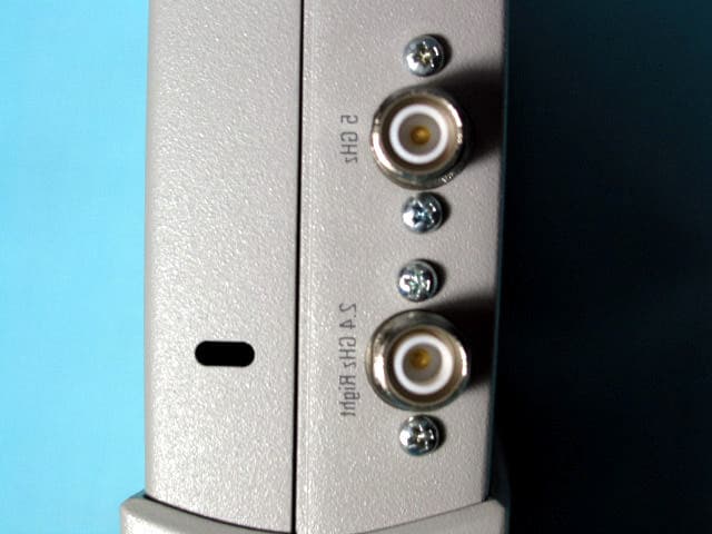
RVW2230W
Jun 19, 2004802.11 Dual Band Access Point
Equipment Class
NII - Unlicensed National Information Infrastructure TX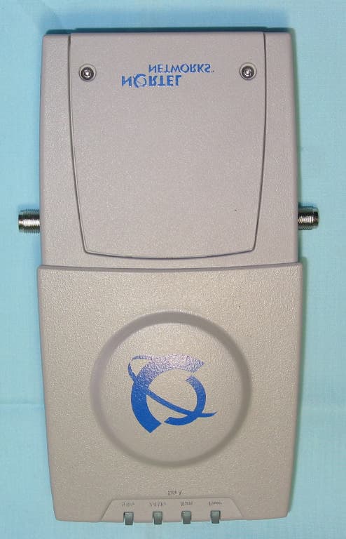
RVW2231
Mar 25, 20042.4 GHz 802.11 Access Point
Equipment Class
DTS - Digital Transmission System