RXZ-CB80211GWireless LAN Cardbus Adapter
Pro-Nets Technology Corporation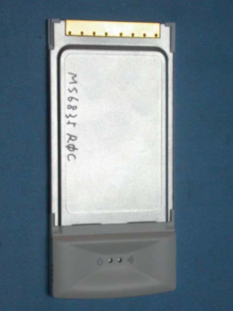
Click to zoom
Application Details
- Equipment Class
- DTS - Digital Transmission System
- Date of Grant
- May 10, 2004
- Application Purpose
- Original Equipment
- Date of Application
- May 10, 2004
- Equipment Note
- Wireless LAN Cardbus Adapter
- Frequency Range
- 2412.00000000 - 2462.00000000
- Country
- Taiwan
Documents & Files
Document Text
Text extracted from the exhibit documents filed with the FCC. Open a document above to read the original.
Users Manual
CB54G2, MS-6835 Wireless 11g CardBus Card User’ s Guide FCC Caution 1.The device complies with Part 15 of the FCC rules. Operation is subject to the following two conditions: (1) This device may not cause harmful interference, and (2) This device must accept any interference received, including interference that may cause undesired operation. 2. FCC RF Radiation Exposure Statement: This equipment complies with FCC RF radiation exposure limits set forth for an uncontrolled environment. This device has been tested for compliance with FCC RF Exposure (SAR) limits in typical laptop configurations. 3.This Transmitter must not be co-located or operating in conjunction with any other antenna or transmitter. 4.Changes or modifications to this unit not expressly approved by the party responsible for compliance could void the user authority to operate the equipment. Copyright Notice The material in this document is the intellectual property of MICRO-STAR INTER- NATIONAL. We take every care in the preparation of this document, but no guaran- tee is given as to the correctness of its contents. Our products are under continual improvement and we reserve the right to make changes without notice. Trademarks Microsoft Windows and Internet Explorer are registered trademarks or trademarks of Microsoft Corporation. All brand names, icons, and trademarks used in this manual are the sole property of their respective owners. Revision History RevisionHistoryDate V 1.0First ReleaseNovember 2003 Important Safety Precautions Always read and follow these basic safety precautions carefully when handling any piece of electronic component. 1.Keep this User’ s Manual for future reference. 2.Keep this equipment away from humidity. 3.Lay this equipment on a reliable flat surface before setting it up. 4.The openings on the enclosure are for air convection hence protects the equipment from overheating. 5.All cautions and warnings on the equipment should be noted. 6.Never pour any liquid into the opening that could damage or cause electrical shock. 7.If any of the following situations arises, get the equipment checked by a service personnel: Liquid has penetrated into the equipment The equipment has been exposed to moisture The equipment has not work well or you can not get it work according to User’ s Manual The equipment has dropped and damaged If the equipment has obvious sign of breakage 8.DO NOT LEAVE THIS EQUIPMENT IN AN ENVIRONMENT UNCONDI- TIONED, STORAGE TEMPERATURE ABOVE 60 O C OR BELOW -20 O C, IT MAY DAMAGE THE EQUIPMENT. How to Use This Guide This User’ s Guide provides instructions and illustrations on how to install and use your MSI CB54G2 - the Wireless 11g CardBus Card. Chapter 1, Introduction, provides a general information on the product you bought, including its application, specification, and requirements. Chapter 2, Installing Your CB54G2, tells you how to install the product into your system. Please note that the setting diagrams or values in this guide are FOR YOUR REFER- ENCE ONLY. The actual settings and values depend on your system and network. If you are not sure about these information, please ask your network administrator or MIS staff for help. Technical Support Visit the MSI website for FAQ, technical guide, driver and software updates, and other information: http://www.msi.com.tw/. Contact our technical staff at: [email protected]. Table of Contents 1. Introduction ..................................................................................... 1 1.1 CB54G2 - Wireless 11g CardBus Card ............................................................... 1 1.2 How CB54G2 Works .......................................................................................... 2 1.3 Specifications ....................................................................................................... 4 1.4 System Requirements .......................................................................................... 6 1.5 Package Contents ................................................................................................. 6 1.6 Product View ....................................................................................................... 7 2. Installing Your CB54G2 ................................................................ 8 2.1 Connecting the CB54G2 ...................................................................................... 8 2.2 Removing the CB54G2 ........................................................................................ 9 2.3 Installing the Driver and Utility .......................................................................... 10 2.4 The MSI Wireless LAN Icon .............................................................................. 12 1 Wireless 11g CardBus Card CB54G2 User’s Guide CB54G2 (MS-6835) - Wireless 11g CardBus Card CB54G2 (MS-6835), compliant with IEEE802.11g stand- ard, is compliant with IEEE802.11g, is a high-efficiency wireless adapter for wireless networking at home, in of- fice or in public places. The data rate can be up to 54 Mbps and auto-negotiated to 48, 36, 24, 18, 12, 9, 6Mbps (IEEE 802.11g), or 11, 5.5, 2, 1Mbps (IEEE802.11b). With CB54G2, you can roam between conference room and office without being disconnected the LAN cables; in addition, sharing files and printers can be easy tasks. The CB54G2 is available to Microsoft Windows operating systems (Windows ® XP/2000/ME/98SE) and can be inte- grated into networking with either Ad-hoc mode (computer-to-computer, without an Access Point) or Infra- structure mode (computer-to-access point, an Access Point is required). >>> 1.1 Introduction 2 Wireless 11g CardBus Card CB54G2 User’s Guide How CB54G2 Works Ad-hoc Mode : An Ad-hoc network is a local area network, especially one with wireless or temporary plug-in connec- tions. Therefore, some of the network devices are part of the network only for the duration of a communications ses- sion. Users in the network can share fil…
Text truncated - open the document above for the full version.
Users Manual
6 Wireless 11g CardBus Card CB54G2 User’s Guide System Requirements Before installing the CB54G2, your PC should meet the following: - Notebook PC with PC Card slot, or desktop PC with PC Card slot module. - Windows ® 98SE/ME/2000/XP operating system. - Minimum 5MB free disk space for installing the driver and utilities. - CD-ROM drive, double speed or higher. >>> 1.4 >>> 1.5Package Contents Unpack the package and check all the items carefully. If any item contained is damaged or missing, please con- tact your local dealer as soon as possible. Also, keep the box and packing materials in case you need to ship the unit in the future. The package should contain the follow- ing items: - One Wireless 11g CardBus Card - CB54G2. - One Quick Start Guide. - One software CD-ROM including drivers, utilities, User’s Guide and Quick Start Guide. 7 Wireless 11g CardBus Card CB54G2 User’s Guide Product View>>> 1.6 Golden Finger Power LED - Solid BLUE, indicating that the CB54G2 is power on. Link LED - BLUE, indicating the networking status by: ON - CB54G2 is connected. Flash - CB54G2 is searching for available Access Point or receiving/transmitting data over the wireless network. 8 Wireless 11g CardBus Card CB54G2 User’s Guide Installing Your CB54G2 >>> 2.1 Connecting the CB54G2 Locate the PC card slot on your notebook computer. If there is the dummy card in the slot, remove it first; then, insert the CB54G2 into the slot (usually with its label facing up) and push it until it is firmly seated. DO NOT hold the CB54G2 on the golden finger when installing it; otherwise, it may cause interference or damage. PC card slot Connect the CB54G2 9 Wireless 11g CardBus Card CB54G2 User’s Guide >>> 2.2 Removing the CB54G2 Press the Eject Button to make it stretch out. Push the Eject Button and the CB54G2 will slide out slightly. Then, pull it out of the slot. Eject Button Before removing the CB54G2, you should stop the device in Windows operating system. Remove the CB54G2 10 Wireless 11g CardBus Card CB54G2 User’s Guide Click Tip: The card should be installed into your computer before installing the driver and utility. >>> 2.3 Installing the Driver and Utility This section describes the procedures of installing the driver and utility. Follow the instruction step by step to finish the installation. If you use Windows ® 98SE/ME, please prepare the Windows ® Setup CD at hand before installing the driver; because the system will ask you to insert the Setup CD to copy files during the installation. Please NOTE that the CB54G2 should be installed into your computer before installing the driver and utility. Then, turn on the computer, and the operating system will detect a new device and start to configure the new device. Click Cancel here to start installation from the InstallShield Wiz- ard. Insert the software CD into your CD-ROM drive, and the Setup program should launch automatically. If the Autorun program doesn’t launch automatically, click Start at the taskbar and select Run.... Type E:\setup.exe in the Open box and click OK (E is your CD-drive) to launch the Setup program manually. The main screen of Setup program will appear as below. Click the Install Software button. Step 1. 11 Wireless 11g CardBus Card CB54G2 User’s Guide MSI Wireless LAN icon Click Finish when the installation is completed. The MSI Wireless LAN icon will appear in the status area. Step 4. Click Install and the program will copy the necessary files to the system. The progress indicator shows the install- ing status. Tips: If you use Windows 98SE/ME, you may be asked to insert the Windows Setup CD during the installation. Please insert the Setup CD by the on-screen instruction to continue the installation. Step 3. The welcome screen of InstallShield Wizard appears. click Next. Read and accept the License Agreement; then, click Next. in the following window, enter the user’ s information (User Name, Organization) in the respective fields; then, click Next. Step 2. Click 12 Wireless 11g CardBus Card CB54G2 User’s Guide >>> 2.4 Right-clicking the icon will bring up a shortcut menu con- taining more settings: The MSI Wireless LAN Icon After installing the driver, the CB54G2 provides a conven- ient and powerful Wireless Network Utility, allowing you to set up, configure, and know your networking status easily and clearly. The MSI Wireless LAN Icon - Not connected to the network. - Connected to the network. - Receiving/transmitting data from/to the network. When you move the mouse over the icon, it shows the current connection information. Language You can select language according to your operating system. Switch to AP Mode This function allows you to use your MSI wireless adapter as a virtual access point. 13 Wireless 11g CardBus Card CB54G2 User’s Guide Switch to Gateway Mode This function allows you to use your MSI wireless adapter as a virtual gateway. Open Network Connections Select to open the Network Connections window. View Available Wireless Networks Launch the utility to configure your network settings. Exit Close the program. Clicking the icon will launch the utility as shown below to configure your network settings.
External Photos
Company : PRO-NETS TECHNOLOGY CORPORATION Page : 1 of 2 Product : Wireless LAN Cardbus Adapter Model : CB80211G Company : PRO-NETS TECHNOLOGY CORPORATION Page : 2 of 2 Product : Wireless LAN Cardbus Adapter Model : CB80211G
ID Label/Location Info
Company: PRO-NETS TECHNOLOGY CORPORATION Model: CB80211G Product : Wireless LAN Cardbus Adapter Wireless LAN Cardbus Adapter Model No: CB80211G FCC IDRXZ-CB80211G This device complies with part 15 of the FCC Rules. Operation is subject to the following two conditions: [1] this device may not cause harmful interference and [2] this device must accept any interference received, including interference that may cause undesired operation. S/N Made in Taiwan
Internal Photos
Company : PRO-NETS TECHNOLOGY CORPORATION Page : 1 of 2 Product : Wireless LAN Cardbus Adapter Model : CB80211G Company : PRO-NETS TECHNOLOGY CORPORATION Page : 2 of 2 Product : Wireless LAN Cardbus Adapter Model : CB80211G
Operational Description
4 Specifications Form FactorCardBus Operation voltage3.3V StandardIEEE 802.11g/IEEE 802.11b Frequency Range2.4GHz to 2.4835GHz Data Rate andIEEE 802.11b(Auto-Fallback): Modulation Types- CCK @ 5.5 and 11 Mbps - DQPSK @ 2Mbps - DBPSK @ 1 Mbps IEEE 802.11g(Auto-Fallback): - OFDM @ 54, 48, 36, 24, 18, 12, 9, 6 Mbps Operating Channels- U.S. and Canada: 11 - Eurpoe: 1 ~ 13 - France: 4 - Spain: 2 - Japan: 13 Media Access ProtocolDirect Sequence Spread Spectrum (DSSS) with ACK; Half-Duplex Security / Encryption64-/128-bit WEP RangeOpen space: up to 350m AntennaPrinted antenna Operating systemMicrosoft ® Windows ® 98SE/ ME/2000/XP EnvironmentalOperating Temperature: 0 ~ 55 O C Operating Humidity: 10 ~ 90%, non-condensing >>> 1.3 5 EMI ComplianceFCC, CE, Wi-Fi Dimensions (WxDxH)115 X 54 X 6.7mm Weight40g
RF Exposure Info
Report No. : ES/2004/50003 Page : 1 of 40 TEST REPORT Equipment Under Test : Wireless LAN Cardbus Adapter Model No. : CB80211G FCC ID : RXZ-CB80211G Applicant : PRO-NETS TECHNOLOGY CORPORATION Address of Applicant : 10F-1, No.92, Pao-Chung Road, Hsin Tien Taipei, Ta i w a n , R . O . C . Date of Receipt : 2004.05.07 Date of Test(s) : 2003.11.14-2003.11.17 Date of Issue : 2004.05.10 Standards: FCC OET Bulletin 65 supplement C, ANSI/IEEE C95.1 , C95.3 In the configuration tested, the EUT complied with the standards specified above. Remarks: This report details the results of the testing carried out on one sample, the results contained in this test report do not relate to other samples of the same product. The manufacturer should ensure that all products in series production are in conformity with the product sample detailed in this report. This report may only be reproduced and distributed in full. If the product in this report is used in any configuration other than that detailed in the report, the manufacturer must ensure the new system complies with all relevant standards. Any mention of SGS Taiwan E&E Services or testing done by SGS Taiwan E&E Services in connection with distribution or use of the product described in this report must be approved by SGS Taiwan E&E Services in writing. Tested by : Dikin Yang Date : 2004.05.10 Approved by : Robert Chang Date : 2004.05.10 Report No. : ES/2004/50003 Page : 2 of 40 Contents 1. General Information 1.1 Testing Laboratory 3 1.2 Details of Applicant 3 1.3 Description of EUT(s) 3 1.4 Test Environment 4 1.5 Operation description 4 1.6 Evaluation procedures 4 1.7 The SAR Measurement System 5 1.8 System Components 7 1.9 SAR System Verification 8 1.10 Tissue Simulant Fluid for the Frequency Band 2.4 to 2.5 GHz 9 1.11 Test Standards and Limits 10 1.12 References 12 2. Instruments List 13 3. Summary of Results 14 4. Measurements 15 802.11b 4.1.1 End-on position, lowest channel 15 4.1.2 End-on position, middle channel 16 4.1.3 End-on position, highest channel 17 4.1.4 Edge-on position, lowest channel 18 4.1.5 Edge-on position, middle channel 19 4.1.6 Edge-on position, highest channel 20 802.11g 4.2.1 End-on position, lowest channel 21 4.2.2 End-on position, middle channel 22 4.2.3 End-on position, highest channel 23 4.2.4 Edge-on position, lowest channel 24 4.2.5 Edge-on position, middle channel 25 4.2.6 Edge-on position, highest channel 26 4.3 System Performance Validation 27 APPENDIX 1. Photographs of Test Setup 28 2. Photographs of EUT 32 3. Probe Calibration certificate 34 4. Uncertainty Analysis 38 5. Phantom description 39 6. System Validation from Original equipment supplier 40 Report No. : ES/2004/50003 Page : 3 of 40 1. General Information 1.1 Testing Laboratory SGS Taiwan Ltd. 1F, No. 134, Wukung Road, Wuku industrial zone Taipei county , Taiwan , R.O.C. Telephone : +886-2-2299-3279 Fax : +886-2-2298-2698 Internet : http://www.sgs.com.tw 1.2 Details of Applicant Applicant : PRO-NETS TECHNOLOGY CORPORATION Address : 10F-1, No.92, Pao-Chung Road, Hsin Tien Ta i p e i , Ta i w a n , R . O. C . 1.3 Description of EUT(s) Equipment Type Wireless LAN Cardbus Adapter Test Procedure FCC OET Bulletin 65, Supplement C TX Frequency range 2412-2462 MHz FCC ID RXZ-CB80211G Serial No. Pre-Production Model(s) CB80211G Modulation Direct Sequence Spread Spectrum (DSSS) 802.11b Mode 802.11g Mode RF Conducted Output Power 16.73 dBm (2412MHz) 16.18 dBm (2437MHz) 15.35 dBm (2462MHz) 12.78 dBm (2412MHz) 12.22 dBm (2437MHz) 11.38 dBm (2462MHz) Report No. : ES/2004/50003 Page : 4 of 40 Max. SAR Measured 0.331 W/kg Antenna Type Printed Power Supply From PCMCIA slot 3.3V/5V Host Laptop PC(s) Tested IBM ThinkPad T30 (S/N: 99AMZM5) Note This Test Report is refer to original ER/2003/B0017. The sample is identical with previous one 1.4 Test Environment Ambient temperature : 22.4° C Tissue Simulating Liquid : 21.4° C Relative Humidity : 64 % 1.5 Operation Configuration The EUT is PCMCIA Card, which is installed inside a Notebook. Since the Notebook is placed on the top of the leg, when it operates, it is to be defined as a portable device. SAR measurement is mandatory. In order to measure SAR value, we used continuous transmission mode. The test set up mode was prepared by manufacturer. Value of Crest Factor = 1 was used for SAR testing according to the nature of the EUT. The test configuration tested at the low, middle and high frequency channels (2412MHz,2437MHz and 2462MHz).By using the program subordinated in the computer, and change into the written channel, and then set in highest power. Finally, we will test it by dividing into 2 ways. Configuration 1: “End-on” placement; Bottom of the Pc is paralleled and at a distance of 0.0 cm from the base of the phantom, but 1.3 cm Spacing between EUT & Planar Phantom . (Fig.3 & Fig.4 &Fig.5) Configuration 2: “ Edge-on” placement; edge of the PC at 90° and at a distance of 1.5 cm from the base of the phantom. (Fig.6 & Fig.7 & Fig.8) 1.6 EVALUATION PROCEDURES The evaluation was performed with the following procedure: Report No. : ES/2004/50003 Page : 5 of 40 (1). Measurement of the SAR value at a fixed location above the ear point or central position of flat phantom was used as a reference value for assessing the power drop. (2). The SAR distribution at the exposed side of head or body position was measured at a distance of each device from the inner surface of the shell. The area covered the entire dimension of the head or EUT and the horizontal grid spacing was 15 mm x 15 mm. Based on these data, the area of the maximum absorption was determined by splint interpolation. (3). Around this point, a volume of 30 mm x 30 mm x 30 mm was assessed by measuring 7 x7 x 7 points. On the basis of this data set, the spatial peak SAR value was evaluated under the following procedure: 1. The data at the surface were extrapolated, since the center of the dipoles is 2.7 mm away from the tip of the probe and the distance between the surface and …
Text truncated - open the document above for the full version.
Test Report
Ecom Sertech Corp. Rm. 258, Bldg. 17, NO.195, Sec. 4 Chung Hsing Rd.,Chu -Tung Chen, Hsinchu, Taiwan 310, R.O.C TEL:886 - 3 - 5918012 FAX : 886 - 3 - 5825720 FCC ID :RXZ-CB80211G Report No.:ER04-04-072FRF Page 1 of 60 TEST REPORT Product Name : Wireless LAN Cardbus Adapter Model Number : CB80211G Applicant : PRO-NETS TECHNOLOGY CORPORATION Address : 10F-1, No. 92, Pao-Chung Road, Hsin Tien Taipei, Taiwan, R.O.C. Received Date : Apr. 28, 2004 Tested Date : Nov. 04~11, 2003 Notes : 1. This report will be invalid if duplicated or photocopied in part. 2. This report refers only to the specimen(s) submitted to testing, and be invalid as seperately used. 3. This report is invalid without examination stamp and signature of this institute. 4. The tested specimen(s) will be preserved for thirty days from the data issued. 5. The report must not be used to claim product certification, approval, or endorsement by NVLAP, NIST, or any agency of the federal government. 6. This report is transferred from ER03-11-009. Ecom Sertech Corp. Rm. 258, Bldg. 17, NO.195, Sec. 4 Chung Hsing Rd.,Chu -Tung Chen, Hsinchu, Taiwan 310, R.O.C TEL:886 - 3 - 5918012 FAX : 886 - 3 - 5825720 FCC ID :RXZ-CB80211G Report No.:ER04-04-072FRF Page 2 of 60 Test Report Certification Product Name : Wireless LAN Cardbus Adapter Model Number : CB80211G Applicant : PRO-NETS TECHNOLOGY CORPORATION Measurement Standard : FCC 47 C.F.R. Part 15, Subpart B and Subpart C (2003), ANSI C63.4 (2001) WE HEREBY CERTIFY THAT: The measurements shown in the attachment were made in accordance with the procedures indicated, and the energy emitted by the equipment was found to be within the limits applicable. We assume full responsibility for the accuracy and completeness of these measurements and vouch for the qualifications of all persons taking them. Ecom Sertech Corp. Rm. 258, Bldg. 17, NO.195, Sec. 4 Chung Hsing Rd.,Chu -Tung Chen, Hsinchu, Taiwan 310, R.O.C TEL:886 - 3 - 5918012 FAX : 886 - 3 - 5825720 FCC ID :RXZ-CB80211G Report No.:ER04-04-072FRF Page 3 of 60 TABLE OF CONTENTS TITLE PAGE NO. 1. GENERAL INFORMATION ........................................................................................5 1.1 General Statement........................................................................................................5 1.2 General Description of EUT & Power.........................................................................5 1.3 Description of Peripherals ...........................................................................................6 1.4 EUT & Peripherals Setup Diagram .............................................................................7 1.5 EUT Operating Condition ...........................................................................................7 1.6 Description of Test Site ...............................................................................................8 1.7 Summary of Test Results.............................................................................................8 2. CONDUCTED POWERLINE TEST............................................................................8 2.1 Test Equipments ..........................................................................................................9 2.2 Test Setup ....................................................................................................................9 2.3 Conducted Power Line Emission Limit.......................................................................10 2.4 Test Procedure .............................................................................................................10 2.5 Uncertainty of Conducted Emission............................................................................10 2.6 Conducted RF Voltage Measurement..........................................................................11-12 2.7 Photos of Conduction Test ..........................................................................................13 3. RADIATED EMISSION TEST .....................................................................................14 3.1 Test Equipments ..........................................................................................................14 3.2 Test Setup ....................................................................................................................14 3.3 Radiation Limit ............................................................................................................15 3.4 Test Procedures............................................................................................................16 3.5 Uncertainty of Radiated Emission ...............................................................................16 3.6 Radiated RF Noise Measurement ................................................................................17-42 3.7 Photos of Open Site .....................................................................................................43-44 4. 6dB BANDWIDTH MEASUREMENT ........................................................................45 4.1 Test Equipments ..........................................................................................................45 4.2 Test Setup ....................................................................................................................45 4.3 Limits of 6dB Bandwidth Measurement......................................................................45 4.4 Test Procedure .............................................................................................................45 4.5 Uncertainty of Conducted Emission............................................................................45 4.6 Test Results..................................................................................................................46 4.7 Photo of 6db Bandwidth Measurement .......................................................................47-48 5. MAXIMUM PEAK OU…
Text truncated - open the document above for the full version.
Test Setup Photos
Ecom Sertech Corp. Rm. 258, Bldg. 17, NO.195, Sec. 4 Chung Hsing Rd.,Chu -Tung Chen, Hsinchu, Taiwan 310, R.O.C TEL:886 - 3 - 5918012 FAX : 886 - 3 - 5825720 FCC ID :RXZ-CB80211G Report No.:ER04-04-072FRF Page 13 of 60 2.7 Photos of Conduction Test Ecom Sertech Corp. Rm. 258, Bldg. 17, NO.195, Sec. 4 Chung Hsing Rd.,Chu -Tung Chen, Hsinchu, Taiwan 310, R.O.C TEL:886 - 3 - 5918012 FAX : 886 - 3 - 5825720 FCC ID :RXZ-CB80211G Report No.:ER04-04-072FRF Page 43 of 60 3.7 Photos of Open Site Ecom Sertech Corp. Rm. 258, Bldg. 17, NO.195, Sec. 4 Chung Hsing Rd.,Chu -Tung Chen, Hsinchu, Taiwan 310, R.O.C TEL:886 - 3 - 5918012 FAX : 886 - 3 - 5825720 FCC ID :RXZ-CB80211G Report No.:ER04-04-072FRF Page 44 of 60
Contact Information
Applicant
Alex Chen(R & D DIRECTOR)
Test Firm
ECOM Sertech Corp.C. Wu
Technical Specifications
| # | Rule Parts | Frequency Range | Power Output |
|---|---|---|---|
| 1 | 15C | 2.41 GHz - 2.46 GHz | 47.10 mW |
Other Applications from Pro-Nets Technology Corporation
RXZ-WR861R
Jun 01, 2011Wireless Router
Equipment Class
DTS - Digital Transmission System
RXZ-WPE81R
Apr 20, 2011Wireless PCIE Card
Equipment Class
DTS - Digital Transmission System
RXZ-WA45R1
Feb 01, 2011Wireless ADSL Router
Equipment Class
DTS - Digital Transmission System
RXZ-WU71R
Dec 06, 2010Wireless USB Dongle
Equipment Class
DTS - Digital Transmission System
RXZ-WP82RL
Oct 24, 2010Wireless PCI Card
Equipment Class
DTS - Digital Transmission System