RXZ-WPE81RLWIRELESS PCI Express Adapter
Pro-Nets Technology Corporation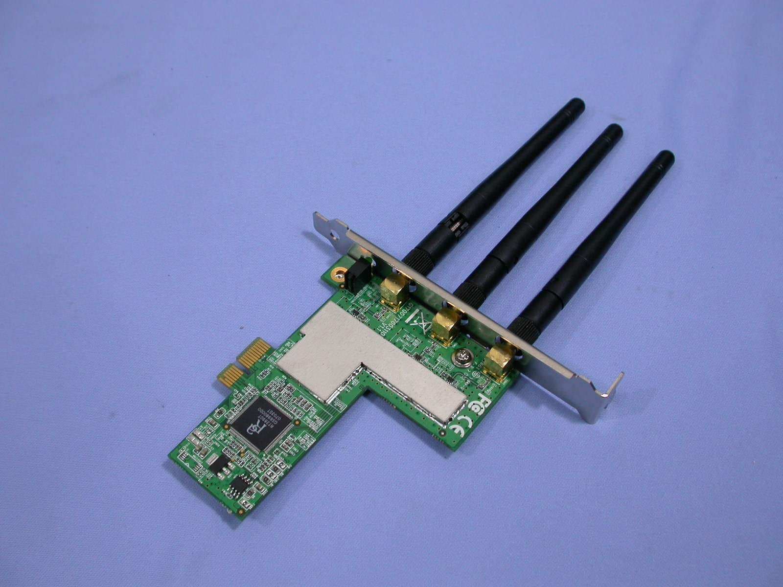
Click to zoom
Application Details
- Equipment Class
- DTS - Digital Transmission System
- Date of Grant
- Jan 20, 2008
- Application Purpose
- Original Equipment
- Date of Application
- Jan 20, 2008
- Equipment Note
- WIRELESS PCI Express Adapter
- Frequency Range
- 2422.00000000 - 2452.00000000
- Country
- Taiwan
Documents & Files
Document Text
Text extracted from the exhibit documents filed with the FCC. Open a document above to read the original.
Users Manual
IEEE 802.11n Wireless PCI Express Adapter User’s Manual November 2007 1 FCC Warning This equipment has been tested and found to comply with the limits for a Class B digital device, pursuant to part 15 of the FCC Rules. These limits are designed to provide reasonable protection against harmful interference in a residential installation. This equipment generates, uses, and can radiate radio frequency energy and, if not installed and used in accordance with the instructions, may cause harmful interference to radio communication. However, there is no guarantee that interference will not occur in a particular installation. If this equipment does cause harmful interference to radio or television reception, which can be determined by turning the equipment off and on, the user is encouraged to try to correct the interference by one or more of the following measures: - Reorient or relocate the receiving antenna. - Increase the separation between the equipment and receiver. - Connect the equipment into an outlet on a circuit different from that to which - Consult the dealer or an experienced radio/TV technician for help. the receiver is connected. FCC Caution: Any changes or modifications not expressly approved by the party responsible for compliance could void the user’s authority to operate this equipment. This device complies with Part 15 of the FCC Rules. Operation is subject to the following two conditions: (1) This device may not cause harmful interference, and (2) this device must accept any interference received, including interference that may cause undesired operation. IMPORTANT NOTE: FCC Radiation Exposure Statement: This equipment complies with FCC radiation exposure limits set forth for an uncontrolled environment. This equipment should be installed and operated with a minimum distance of about eight inches (20cm) between the radiator and your body. This transmitter must not be co-located or operated in conjunction with any other antenna or transmitter. 2 IMPORTANT NOTE: In the event that these conditions cannot be met (for example certain laptop configurations or co-location with another transmitter), then the FCC authorization is no longer considered valid and the FCC ID cannot be used on the final product. In these circumstances, the OEM integrator will be responsible for re-evaluating the end product (including the transmitter) and obtaining a separate FCC authorization. Revision History Revision History V1.1 2nd release All brand and product names mentioned in this manual are trademarks and/or registered trademarks of their respective holders. 3 Contents 1. Introduction................................................................ 4 1.1 Features.................................................................................................. 4 1.2 LED Indicator ......................................................................................... 4 1.3 Package Contents ................................................................................. 5 1.4 Before you start ..................................................................................... 5 1.5 Hardware Installation ............................................................................ 5 2. Installation Procedure ............................................... 7 2.1 For Windows XP and 2000.................................................................... 7 2.2 For Vista ............................................................................................... 12 3. Wireless Network Configuration Utility ................. 17 3.1 For Windows XP & 2000 .......................................................................... 17 3.1.1 Start........................................................................................... 23 3.1.2 Profile........................................................................................ 29 3.1.3 Network..................................................................................... 34 3.1.4 Advanced.................................................................................. 35 3.1.5 Statistics................................................................................... 36 3.1.6 WMM ......................................................................................... 37 3.1.7 WPS........................................................................................... 43 3.1.8 About ........................................................................................ 46 3.1.9 Link Status ............................................................................... 46 3.1.10 Enable AP Mode Feature in Windows 2000 OS ................... 47 3.2 For Windows Vista................................................................................... 53 3.2.1 Profile........................................................................................ 53 3.2.2 Link Status ............................................................................... 61 3.2.3 Site Survey ............................................................................... 62 3.2.4 Statistics................................................................................... 68 3.2.5 WPS Configuration .................................................................. 69 3.2.6 QoS ........................................................................................... 71 3.2.7 About ........................................................................................ 78 3.2.8 How to Manage Windows Profile ........................................... 79 4. Troubleshooting ...................................................... 83 4 1. Introduction This is a wireless PCI Express adapter that delivers unrivaled wireless performance for your Desktop PC. It complies with IEEE 802.11n draft standard and backward compatible with IEEE 802.11b/g. With this adapter, you can easily upgrade your Desktop PC wireless connectivity. Once connected, access the network wit…
Text truncated - open the document above for the full version.
Users Manual
33 Step 3: Change profile name to what you want to connect. Pull down the SSID and select one intended AP. The AP list is the result of last Network. Step 4: Then, you can see the profile which you set appear in the profile list. Click “Activate” to activate the profile setting. 34 3.1.3 Network Under the Network function, system will display the information of surrounding APs from last scan result. List information includes SSID, BSSID, Signal, Channel, Encryption algorithm, Authentication and Network type as below: [Definition of each field] SSID: Name of BSS or IBSS network Network Type: Network type in use, infrastructure for BBS, Ad-Hoc for IBSS network Channel: Channel in use. Wireless Mode: AP support wireless mode. IT may support 802.11b, 802.11g or 802.11n wireless mode. Security-Enable: Whether AP provides security-enabled wireless network Signal: Receive signal strength of specified network [Icons & Buttons] Î Indicate connection is successful. Î Indicate network type is infrastructure mode. Î Indicate network type is Ad-Hoc mode. Î Indicate security-enabled wireless network. Î Indicate 802.11b wireless mode. Î Indicate 802.11g wireless mode. Î Indicate 802.11n wireless mode. Î Indicate the AP lists are sorted by SSID, Channel, or Signal. Î Command to connect to the selected network. 35 Î Issue a rescan command to wireless NIC to update information on surrounding wireless network. Î Add the selected AP to Profile setting. It will bring up profile page and save user’s setting to a new profile. [Connected Network] (1) When RaUI first ran, it will select the best AP to connect automatically. (2) If user wants to connect to other AP, He can click “Connect: button for the intended AP to make connection. (3) If the intended network has encryption other than “Not Use”, RaUI will bring up the security page appropriate information to make the connection. (4) When you double-click on the intended AP, you can see AP’s detail information. 3.1.4 Advanced Wireless Mode: Select wireless mode. 802.11B only, 802.11B/G mix, and 802.11B/G/N mix, modes are supported. (802.11 B/G mix selection item only exists for B/G adapter; 802.11B/G/N mix selection item only exists for B/G/N adapter; 802.11 B/G/N mix selection item only exists for A/B/G/N adapter.) Wireless Protection: User can choose from Auto, On, and Off (Only 802.11n adapter don’t support) Î Auto: STA will dynamically change as AP announcement Î ON: Always send frame with protection. Î Off: Always send frame without protection. TX Rate: Manually force the Transmit using selected rate. Default is auto. (802.11n wireless card doesn’t support.) 36 Enable Tx Burst: Ralink’s proprietary frame burst mode. Enable TCP Windows Size: Enhance throughout. Fast Roaming at: Fast to roaming, setup by transmit power. Select your Country Region Code: 8 countries to choose. Show Authentication Status Dialog: When you connect AP with authentication, choose whether show “Authentication Status Dialog” or not. Authentication Status Dialog display the process about 802.11x Authentication. Enable CCX (Cisco Compatible eXtensions): support Cisco Compatible Extensions function. Î LEAP turn on CCKM Î Enable Radio Measurement: can channel measurement every 0~2000 milliseconds. Apply: Save the save changes Î Show the information of Status Section Î Hide the information of Status Section 3.1.5 Statistics Statistics page displays the detail counter information based on 802.11 MIB counters. This page translates the MIB counters into a format easier for user to understand. [Transmit Statistics] Frames Transmitted Successfully: Frames successfully sent. Frames Fail To Receive ACK After All Retries: Frames failed transmit after hitting retry limit. RTS Frames Successfully Receive CTS: Successfully receive CTS after sending RTS frame. RTS Frames Fail to Receive CTS: Fail to receive CTS after sending RTS frame. Frames Retransmitted Successfully: Successfully retransmitted frames numbers Reset Counter: Reset counters to zero 37 [Receive Statistics] Frames Received Successfully: Frames received successfully. Frames Received With CRC Error: Frames receive with CRC error. Frames Dropped Due To Out-Of-Resource: Frames dropped due to resource issue. Duplicate Frames Received: Duplicate received frames. Reset Counter: Reset counters to zero Î Show the information of Status Section Î Hide the information of Status Section 3.1.6 WMM WMM function involves “WMM Enable”, “WMM-Power Save Enable” and “DSL Setup”. WMM Enable: Enabe Wi-Fi Multi-Media. WMM-Power Save Enable: Enable WMM Power Save. Direct Link Setup Enable: Enable DLS (direct Link Setup). [WMM Enable – Enable Wi-Fi Multi-Media] If you want to use “WMM-Power Save” or “Direct Link Setup” you must enable WMM. The 38 setting methods of enabling WMM indicating as follow: Step 1: Click “WMM Enable” Step 2: Change to “Network” function. And add an AP that supports WMM features to a Profile. The result will look like the below figure in Profile page. [WMM-Power Save Enable – Enable WMM Power Save] Step 1: Click “WMM-Power Save Enable” 39 Step 2: Please select which ACs you want to enable. The setting of enabling WMM-Power Save is successfully. [Direct Link Setup Enable – Enable DLS (Direct Link Setup)] Step 1: Click “Direct Link Setup Enable” Step 2: Change to “Network” function. And add an AP that supports DLS features to a Profile. The result will look like the below figure in Profile page. 40 The Setting of DLS indicates as follow: (1) Fill in the blanks of Direct Link with MAC address of STA. The STA must conform to 2 conditions as follow: Î Connect with the same AP that support DLS features. Î Have to enable DLS (2) Timeout Value represent that it disconnect automatically after some seconds. The value is integer. The integer must be between 0~65535. It represents that it always connects if the 41 value is zero. Default value of Timeout Value is 60 seconds. (3) Click “Apply” button. The result will look like the below figure. Desc…
Text truncated - open the document above for the full version.
Users Manual
63 WPA-PSK, WPA2-PSK, WPA and WPA2. Network Type: Network type in use, Infrastructure or Ad-Hoc. Rescan: Issue an rescan command to wireless NIC to update information on surrounding wireless network. Re-Scanning: Clicking the re-scan button to perform the re-scanning action. Add to Profile: Add the selected AP to Profile setting. It will bring up profile page and save user’s setting to a new profile. [Connect A Network] (1) When Raconfig first ran, it will select the best AP to connect automatically. (2) If user wants to connect to other AP, he can double-click mouse on the intended AP to make connection. (3) If the intended network has encryption other than “Not Use”, Raconfig will bring up the security page and let use input the appropriate information to make the connection. This icon indicates the changes is successful. ☉Example 1: Open and Non-Encrypted Step 1 – Choose “Open” authentication type Step 2 – Choose “None” encryption type Step 3 – After the profile is saved, click “Activate” button on Profile Page to activate the profile. 64 ☉ Example 2: WEP-Encrypted Step 1 – Choose “Open” or “Shared” authentication type Step 2 – Choose “WEP” encryption type Step 3 –Enter the WEP KEY 65 Step 4 –After the profile is saved, click the “Activate” button on Profile Page to active the profile. ☉ Example 3: WPA-PSK/WPA2-PSK Step 1 – Choose “WPA-PSK” or “WPA2-PSK” authentication type Step 2 – Choose “TKIP” or “AES” encryption type Step 3 –Enter the pre-shared KEY 66 Step 4 –After the profile is saved, click the “Activate” button on Profile Page to active the profile. ☉ Example 4:WPA/WPA2 Step 1 – Choose “WPA” or “WPA2” authentication type Step 2 – Choose “TKIP” or “AES” encryption type 67 Step 3 –After the profile is saved, click the “Activate” button on Profile Page to active the profile. Step 4 –The Windows profile setting dialog is popped-up for user to modify. 68 3.2.4 Statistics Statistics page displays the detail counter information based on 802.11 MIB counters. This page translates the MIB counters into a format easier for user to understand. You may reset the counters to Zero by clicking “Reset Counter”. [Transmit Statistics] Frames Transmitted Successfully: Frames successfully sent Frames Transmitted Successfully After Retry: Frames sent successfully with retry. Frames Fail to Receive ACK After All Retries: Frames failed transmit after hitting retry limit. RTS Frames Successfully Receive CTS: Successfully receive CTS after sending RTS frames. RTS Frames Fail To Receive CTS: Failed to receive CTS after sending RTS frames. [Receive Statistics] Frames Received Successfully: Frames received successfully. Frames Received with CRC Error: Frames received with CRC error. Frames Dropped Due to Out-of-Resource: Frames dropped due to resource issue. Duplicate Frames Received: Duplicate received frames. 69 3.2.5 WPS Configuration The primary goal of Wi-Fi Protected Setup (Wi-Fi Simple Configuration) is to simply the security setup and management of Wi-Fi Networks. WPS Associate IE: If the “WPS Associate IE” option is checked, station will send the association request with WPS IE during WPS setup. WPS Probe IE: If the “WPS Probe IE” option is checked, station will send the probe request with WPS IE during WPS setup. [Display WPS capable AP information] The WPS capable AP information is listed in the upper frame, and the display AP’s characters are SSID, BSSID, current operating channel, device password ID, authentication type, and encryption type. Re-Scanning: Clicking “re-scan” button performs the re-scanning action. WPS AP Information: Clicking the WPS information” button brings up the WPS capable AP information dialog. Authentication Type: there are three type of supported authentication modes, and there are Open, Shared, WPA-PSK and WPA modes. 70 Encryption Type: For Open & Shared authentication modes, the available encryption types are None and WEP. For WPA, WPA2, WPA-PSK and WPA2-PSK authentication modes, the available encryption types are TKIP and AES. Config Methods: This attributes contains the config methods supported and enabled by the selected Registrar. Device Password ID: Device Password ID indicates the method or identifies the specific password that the selected Registrar intends to use. Selected Registrar: Selected Registrar indicates if the user has recently activated a Registrar to add an Enrollee. State: This attribute is used to indicate the current configuration state. This attribute is either “Un-Configured” or “Configured”. Version: This attribute is the specified WPS version. AP Setup Locked: AP Setup Locked indicates if AP has entered a setup locked state. UUID-E: UUID-E is the universally unique identifier (UUID) generated by the Enrollee. RF-Bands: RF Bands indicate the available RF bands. [Configure WPS Profiles] The user can configure WPS profile with either PIN method or PBC method. PIN Method: Step 1 Î The Registrar enters the pin code generated by station. Step 2 Î Click the “PIN” button. PBC Method: Step 1 Î Click the “PBC” button within 2 second while the Registrar clicks the button. [Manage WPS Profiles] The Received WPS profiles are listed in the lower frame, and the listed WPS profile attributes are SSID, MAC address, authentication type, and encryption type. WPS profile detail information: Selecting a profile then clicking the “Detail” button brings up the WPS profile detail information dialog. Connect with WPS Profile: Clicking the “Connect” button will connect to AP with the select WPS profile. Rotate WPS profile: If there are more than two WPS profiles, clicking the “Rotate” button will rotate to next profile and connect to AP with this profile. If the connection can’t be made successfully, station will perform the WPS profile rotation repeatedly. Disconnect from WPS AP: Clicking the “Disconnect” button will stop the WPS 71 connection. Delete WPS profile: Clicking the “Delete” button will delete the selected WPS profile. 3.…
Text truncated - open the document above for the full version.
Cover Letter(s)
1 Lucy Tsai From:Joe Hsieh [[email protected]] Sent:Monday, January 21, 2008 12:24 AM To:Lucy Tsai Subject:Re: PRO-NETS Technology Corp., FCC ID: RXZ-WPE81RL, Assessment NO.: AN08T7495, Notice#1 Attachments:User Manual_01.pdf; 07-10-MAS-234-01_Test Report.pdf Dear Lucy, Sorry for late to reply. Re-Q#1: Attached please find the revised user manual. Re-Q#2: Yes. It's a Spatial Multiplexing MIMO device. Re-Q#3: Attached please find the revised Test report. Re-Q#4: Attached please find the revised Test report. Two transmitter antennas are activated during the radiated emission tests. Any questions please feel free to contact with me. Best regards, Joe ----- Original Message ----- From: "Lucy Tsai" <[email protected]> To: "Joe Hsieh" <[email protected]> Sent: Monday, January 21, 2008 10:49 AM Subject: RE: PRO-NETS Technology Corp., FCC ID: RXZ-WPE81RL, Assessment NO.: AN08T7495, Notice#1 Hi Joe, Any status on this application? Best Regards, Lucy -----Original Message----- From: Lucy Tsai Sent: Sunday, January 13, 2008 5:53 PM To: Lucy Tsai Subject: PRO-NETS Technology Corp., FCC ID: RXZ-WPE81RL, Assessment NO.: AN08T7495, Notice#1 Hi Joe, Please address following issues. 2 Q#1: User manual page 2 indicates this device is a Class C device which should be revised to Class B, please revise. Besides, page 2-3 also indicate the RF exposure statement for OEM integrator which doesn¡¦t agree with this application. As a PCI card concerned, it is categorized an end product but if grantee will like to apply module approval, then please provide modular request letter to show the compliance. Otherwise, please remove it from the user manual. Q#2: Please confirm if this is a Spatial Multiplexing MIMO in advance. Q3#: According to the operational description, this 802.11bgn PCI card can support cyclic delay diversity (CDD) mode but test only investigated the legacy mode. FYI: Based upon TCB/FCC training on May 2005, FCC wants RF conducted spurious emission and PSD tests to be measured with individual TX chain AND with combiner. In the test report, there is no combiner test data. Please provide the test data of CCD mode, including test with combiner in PSD and RF conducted spurious emission to show the compliance. Q#4: For MIMO mode, test report only indicates a transmitter chain was investigated. Please clarify which chain was investigated during the test and provide another transmitter chain¡¦s test data. At the same time, please confirm during Radiated H20/H40 tests, will two transmitter antennas be activated during the radiated emission tests? No information in the test report. The items indicated above must be submitted before processing can continue on the above referenced application. Failure to provide the requested information within 30 days of the original e-mail date may result in application dismissal and forfeiture of the filing fee. Also, please note that partial responses increase processing time and should not be submitted. Any questions about the content of this correspondence should be directed to the e-mail address listed below the name of the sender.
External Photos
FCC ID: RXZ-WPE81RL Sheet A1 of A1 Sheets ETC Report No. : 07-10-MAS-234-01 ANNEX A: EXTERNAL CONSTRUCTION PHOTOS OF EUT 1. Outside view 1 of EUT 2. Outside view 2 of EUT
ID Label/Location Info
ID Location
Internal Photos
FCC ID: RXZ-WPE81RL Sheet B1 of B3 Sheets ETC Report No. : 07-10-MAS-234-01 ANNEX B: INTERNAL CONSTRUCTION PHOTOS OF EUT 1. Inside View 1 of EUT 2. Inside View 2 of EUT FCC ID: RXZ-WPE81RL Sheet B2 of B3 Sheets ETC Report No. : 07-10-MAS-234-01 3. Inside View 3 of EUT 4. Front view of PCB FCC ID: RXZ-WPE81RL Sheet B3 of B3 Sheets ETC Report No. : 07-10-MAS-234-01 5. Rear view of PCB
Parts List/Tune Up Info
SPECIFICATION 1. Description 100 TYPE 2.4G SMA PLUG REVERSE ANTENNA 2. Customer 3. Model No. 4. Part No. 100SPR-A 5. Standard IEEE 802.11b/g Wireless LAN 6. Antenna Profile 108 mm length (see Drawing) 7. Color Black 8. Electrical Characteristics Operating Frequency 2.4~2.5GHz Antenna Type 1/4λ Dipole Sleeve Polarization Type Linear Type of Radiation Toroidal Peak Gain 2.10 dBi Typical Impedance 50 Ohm nominal V.S.W.R. 2.0:1 Max. 9. Mechanical Characteristics Action Swivel Type Connector RP-SMA (M) Core N/A 10. Raw Material Coaxial Cable MIL-C-17 RG-178 B/U Housing TPU Hinge PC+ALLOY
RF Exposure Info
ETC Report No. : 07-10-MAS-234-05 Sheet 1 of 2 Sheets FCC ID. :RXZ-WPE81RL Rev. No 1.0 MAXIMUM PERMISSIBLE EXPOSURE Standard Applicable Section 15.247 (b)(5) : Systems operating under the provisions of this section shall be operated in a manner that ensures that the public is not exposed to radio frequency energy levels in excess of the Commission's guidelines. See § 1.1307(b)(1) of this Chapter. Section 1.1310: The criteria listed in the following table shall be used to evaluate the environment impact of human exposure to radio frequency radiation as specified in 1.1307(b) LIMITS FOR MAXIMUM PERMISSIBLE EXPOSURE (MPE) Frequency Range (MHz) Electric Field Strength (V/m) Magnetic Field Strength (A/m) Power Density (nW/cm 2 ) Average Time (Minutes) (A) Limits for Occupational/control Exposures 300-1500 -- -- F/300 6 1500-100,000 -- -- 5 6 (B) Limits for General Population/Uncontrolled Exposures 300-1500 -- -- F/300 6 1500-100,000 -- -- 1 30 F = Frequency in MHz Calculations Friis transmission formula: P d = ( P out * G ) / ( 4 * pi * r 2 ) Where P d = power density in mW/cm 2 P out = output power to antenna in mW G = gain of antenna in linear scale pi = 3.1416 r = distance between observation point and center of the radiator in cm The limit of P d is 1 mW/cm 2 . If we know the maximum gain of the antenna and the total power input to the antenna, through the calculation, we will know the distance where the P d at 20 cm is meet the limit of MPE. ETC Report No. : 07-10-MAS-234-05 Sheet 2 of 2 Sheets FCC ID. :RXZ-WPE81RL Rev. No 1.0 Result : :: : Worse case is 802.11g mode and 802.11n HT20 mode 802.11g Operation Frequency (GHz) Distance (cm) Maximum Peak Output Power (dBm) Antenna Gain (dBi) Power Density (mW/cm 2 ) 2.412 20 27.21 5.11 0.339 2.437 20 28.07 5.11 0.414 2.462 20 27.19 5.11 0.338 802.11n HT20 Operation Frequency (GHz) Distance (cm) Maximum Peak Output Power (dBm) Antenna Gain (dBi) Power Density (mW/cm 2 ) 2.412 20 27.07 2.1 0.164 2.437 20 28.03 2.1 0.205 2.462 20 27.23 2.1 0.171 The P d at 20 cm distance calculated from the Friis transmission formula is mush smaller than the limit requirement 1 mW/cm 2 . The Installation Manual instructs the user to install the device such that it has a separation of at least 20 cm from persons to comply with the FCC's requirements. This separation of 20 cm more than meets the FCC's and Industry Canada RF exposure requirements.
Test Report
ETC Report No. : 07-10-MAS-234-01 Sheet 1 of 179 Sheets FCC ID. :RXZ-WPE81RL Rev. No 1.0 CONFORMANCE TEST REPORT FOR FCC 47 CFR, Part 15 Subpart C Report No.: 07-10-MAS-234-01 Client: PRO-NETS Technology Corp. Product: WIRELESS PCI Express Adapter Model: WPE81RL FCC ID: RXZ-WPE81RL Manufacturer/supplier: PRO-NETS Technology Corp. Date test item received: 2007/10/30 Date test campaign completed: 2008/01/17 Date of issue: 2008/01/18 The test result only corresponds to the tested sample. It is not permitted to copy this report, in part or in full, without the permission of the test laboratory. Total number of pages of this test report: 179 pages Total number of pages of photos: External photos 1 pages Internal photos 3 pages Setup photos 2 pages Test Engineer Checked By Approved By James James Joe Hsieh ELECTRONICS TESTING CENTER, TAIWAN NO.8, LANE 29, WENMING RD., LESHAN TSUEN, GUISHAN SHIANG, TAOYUAN COUNTY, TAIWAN 33383, R.O.C.TAIWAN, R.O.C. TEL: (03) 3276170~4 INT: +886-3-3276170~4 FAX: (03) 3276188 INT: +886-3-3276188 ETC Report No. : 07-10-MAS-234-01 Sheet 2 of 179 Sheets FCC ID. :RXZ-WPE81RL Rev. No 1.0 Client : PRO-NETS Technology Corp. Address : 7F, No.95, Lide St,Chung Ho City 235,Taipei, Taiwan, R.O.C. Manufacturer : PRO-NETS Technology Corp. Address : 7F, No.95, Lide St,Chung Ho City 235,Taipei, Taiwan, R.O.C. EUT : WIRELESS PCI Express Adapter Trade name : PRO-NETS, Speed Com+, Jet Com, Medilink, Encore Model No. : WPE81RL Power Source : 3.3Vdc Regulations applied : FCC 47 CFR, Part 15 Subpart C (2006) The testing described in this report has been carried out to the best of our knowledge and ability, and our responsibility is limited to the exercise of reasonable care. This certification is not intended to believe the sellers from their legal and/or contractual obligations. The compliance test is only certified for the test equipment and the results of the testing report relate only to the item tested. The compliance test of this report was conducted in accordance with the appropriate standards. It’s not intention to assure the quality and performance of the product. This report shall not be reproduced except in full, without the approval of ETC. This report must not be used by the client to claim product endorsement by NVLAP or any agency of the U.S. Government. Laboratory Introduction: Electronics Testing Center, Taiwan is recognized, filed and mutual recognition arrangement as following: 1 ISO9001: TüV Product Service 2 ISO/IEC 17025: BSMI, CNLA, DGT, NVLAP, CCIBLAC, UL, Compliance 3 Filing: FCC, Industry Canada, VCCI 4 MRA: Australia, Hong Kong, New Zealand, Singapore, USA, Japan, Korea, China, APLAC through CNLA 5 FCC Registration Number: 90588, 91094, 91095 NVLAP Lab Code 200133-0 ETC Report No. : 07-10-MAS-234-01 Sheet 3 of 179 Sheets FCC ID. :RXZ-WPE81RL Rev. No 1.0 Table of Contents Page 1 GENERAL INFORMATION ............................................................................................................5 1.1 Product Description............................................................................................................................5 1.2 Characteristics of Device ...................................................................................................................5 1.3 Test Methodology ..............................................................................................................................5 1.4 Test Facility........................................................................................................................................5 2 PROVISIONS APPLICABLE...........................................................................................................6 2.1 Definition ...........................................................................................................................................6 2.2 Requirement for Compliance.............................................................................................................7 2.3 Restricted Bands of Operation ...........................................................................................................9 2.4 Labeling Requirement........................................................................................................................9 2.5 User Information..............................................................................................................................10 3. SYSTEM TEST CONFIGURATION .............................................................................................11 3.1 Devices for Tested System...............................................................................................................11 3.2 Dscription of Test modes.................................................................................................................11 4 CONDUCTED EMISSION MEASUREMENT.............................................................................12 4.1 Standard Applicable.........................................................................................................................12 4.2 Measurement Procedure...................................................................................................................12 4.3 Conducted Emission Data...............................…
Text truncated - open the document above for the full version.
Contact Information
Applicant
Alex Chen(R & D DIRECTOR)
Test Firm
Electronics Testing Center, TaiwanWin-Po Tsai
Technical Specifications
| # | Rule Parts | Frequency Range | Power Output |
|---|---|---|---|
| 3 | 15C | 2.42 GHz - 2.45 GHz | 585.00 mW |
Other Applications from Pro-Nets Technology Corporation
RXZ-WR861R
Jun 01, 2011Wireless Router
Equipment Class
DTS - Digital Transmission System
RXZ-WPE81R
Apr 20, 2011Wireless PCIE Card
Equipment Class
DTS - Digital Transmission System
RXZ-WA45R1
Feb 01, 2011Wireless ADSL Router
Equipment Class
DTS - Digital Transmission System
RXZ-WU71R
Dec 06, 2010Wireless USB Dongle
Equipment Class
DTS - Digital Transmission System
RXZ-WP82RL
Oct 24, 2010Wireless PCI Card
Equipment Class
DTS - Digital Transmission System