S8L-100154DMAU-UDigital Multi-Carrier Amplifier
Andrew Corporation, Base Station Subsystems Group
Click to zoom
Application Details
- Equipment Class
- PCB - PCS Licensed Transmitter
- Date of Grant
- Jul 12, 2005
- Application Purpose
- Original Equipment
- Date of Application
- Jul 12, 2005
- Equipment Note
- Digital Multi-Carrier Amplifier
- Frequency Range
- 1932.40000000 - 1987.60000000
- Country
- United States
Documents & Files
Document Text
Text extracted from the exhibit documents filed with the FCC. Open a document above to read the original.
Users Manual
RF Power Amplifiers Andrew Corporation – Power Amplifier Group Propriety – Use pursuant to Company Instruction Page 1 of 1 Digital Multi-Carrier Amplifier Model : DMAU-U Operation Instruction Date: June 17, 2005 Ver. 1.0A Ref# FCC ID: S8L-100154DMAU-U RF Power Amplifiers Andrew Corporation – Power Amplifier Group Propriety – Use pursuant to Company Instruction Page 2 of 2 Introduction This document presents a description of the Andrew Digital Multi-carrier Amplifier Unit (DMAU). The DMAU is a 60 Watt (RF), high efficiency base-station amplifier. It accepts as input a digital representation of multiple CDMA carriers and produces a multi-carrier RF signal at its output. The amplifier transmits RF power over a 20MHz instantaneous bandwidth within the US PCS frequency band of 1930MHz to 1990MHz. Up to 15 CDMA2000 carriers or 4 WCDMA carriers can be transmitted by the DMAU within the instantaneous bandwidth. Since the DMAU has been designed for cellular base-station use, it satisfies all relevant transmission requirements, such as spectral mask limits and emission limits called for by the 3GPP2 and 3GPP standards. At rated power and multiple carrier operation, the in band transmit port emissions are below –13dBm/1MHz for all carrier combinations and counts. DMAU Specifications Table 1 below highlights some of the key design specifications that the DMAU satisfies. Table 1: Key DMAU Specifications 1) Input Signal: Multi-Carrier CDMA2000 or WCDMA (Channel Occupied Bandwidth: CDMA2000-1.25MHz, WCDMA-4.21MHz) presented as digital data. 2) Input Signal Format: Multi-Carrier Digital Baseband (Separate I and Q signals over 600Msps LVDS) 3) Overall DC-to-RF efficiency: 14% at 26VDC input and 60WRF output 4) Output Power: 60 Watts total average power. 5) Nominal Input Voltage: +26VDC (+36VDC max for no failure, transmission stops at 32VDC) 6) System Communication Port: 100-base-T Ethernet 7) Operating Temperature Range: -40°C to +55°C 8) Weight: 9Kg; Dimension: 41.51mm(W) x 461mm(D) x 458.83mm(H) 9) Environmental: Sealed for Outdoor Air Cooling DMAU Interface There are a total of six external interfaces to the DMAU. A description of each interface is provided below. 1) Digital Input Port – Accepts Digital data stream representing multiple carriers of CDMA2000 or WCDMA. 2) RF Output Port – Main RF output. 60W average power is delivered across 1 to 15 CDMA2000 carriers or 1 to 4 UMTS carriers. 3) Front Panel Debug Port – RS232 port used for craft access. 4) DC Input Port – +26VDC input port with approximately 16ADC current draw at rated power. 5) Transmit On/Off Switch – A mechanical reset switch used to turn off transmit power(not DC), or to force DMAU into software reset. Located on the front panel. RF Power Amplifiers Andrew Corporation – Power Amplifier Group Propriety – Use pursuant to Company Instruction Page 3 of 3 6) Tri-Color LED – Single LED that illuminates in green, amber, or red depending on operating condition. This interface is located on the front panel. DMAU Circuit Board/Module Functional Descriptions DMAU contains three individual printed circuit boards and two sub-circuit modules. The main transmit path flows through all three circuit boards. A description of these boards and their functions follows. 1) Power Supply Board (RF500501): The power supply board contains the power converter module and other DC-DC converter circuits needed to convert in-coming 26Vdc to 28Vdc, 7.0Vdc, and 3.3Vdc for use by the internal DMAU circuits. Inrush current limiting circuits, input and output filtering circuits, and fuse protection circuits are also included on the PSB. 2) Power Converter Module (RF500480): Converter module used to convert the incoming +26VDC input which is allowed to vary over some limited range and produce a steady, regulated +28VDC output for use by the other DMAU circuits. This module is assembled onto the Power Supply Board. 3) Signal Processing Board (RF500512 ): This board contains the main digital control micro-processor which runs the software needed to control and monitor various DMAU hardware functions. The micro-processor also allows communication with the DMAU is enabled through a RS232 communication port on the front panel. The SPB also holds the Digital-to-Analog Converter (DAC), which creates the analog output which is then amplified through the RF Amplifier Board. 4) RF Amplifier Board (RF500475) : The RF Amplifier Board raises the level of the SPB signal to the rated DMAU output power through a chain of gain stages. A circulator(off board) is included at the end of the transmit path to protect the RF power stages from reverse power flow. 5) Amplifier Module(RF500475) : The Amplifier Module is an impedance matched RF power transistor used multiple times in the Amplifier board to attain the rated RF power of 60W at the output of the DMAU. RF Power Amplifiers Andrew Corporation – Power Amplifier Group Propriety – Use pursuant to Company Instruction Page 4 of 4 DMAU Photographs DMAU Front View Debug Port Tx Enable/Disable Switch LED indicator RF Power Amplifiers Andrew Corporation – Power Amplifier Group Propriety – Use pursuant to Company Instruction Page 5 of 5 DMAU Cover Side View INSTALLATION AND OPERATION SET-UP The DMAU is easy to operate and use, requiring no special cabling since the main input/output and + 26 VDC @ 15 A power connections are all blind mated into a backplane. An inrush limiting circuit on the power supply section even allows for ‘hot’ insertion into the backplane. Transmission of RF power can be turned off with a mechanical switch located on the front panel to allow for manual override of software settings. Finally, an RS232 serial port on the front face-plate allows for local communications to the amplifier microprocessor to enable field diagnostics. Upon initial power-up or reset, the tri-color unit status LED on the front panel of the DMAU will be red. Normal operation, with RF enabled, will be indicated by “flashing” green. Three states of al…
Text truncated - open the document above for the full version.
Cover Letter(s)
1 Chris Harvey From:[email protected] Sent:Monday, July 11, 2005 12:06 PM To: Chris Harvey Subject:RE: Andrew DMAU-U AN05T4900 Chris, The emission designators for CDMA: 1M25F9W WCDMA: 4M20F9W The channel info: CDMA: Lowest 1931.25MHz, Highest:1988.75MHz WCDMA: Lowest 1932.4MHz, Highest: 1987.6MHz. Regards, Wei > Wei, I am looking at some examples people have used for both CDMA and > WCDMA and I see that the Modulation type Designator used is the F9W, > not DXW. That would make the Emission Designators 1M25F9W and 4M20F9W. > Please look into this before your client formally responds. > > Best regards, > > Chris Harvey > Chris Harvey EMC Consultants, LLC > [email protected] > cell 443-622-3300 > > > -----Original Message----- > From: [email protected] [mailto:[email protected]] > Sent: Sunday, July 10, 2005 8:42 PM > To: [email protected] > Subject: Re: Andrew DMAU-U AN05T4900 > > Chris, > > got some info from client: > **************** > I have no idea what their terminology is. CDMA and WCDMA are complex > modulated waveforms which technically means we have both angle and > amplitude modulation. I would guess at the 'D' type since the > modulation we use does transmit a sequence of states(0,0; 0,1; 1,0; > 1,1). I don't have access to the subpart you're referring to, but if > you read it see if with my description in hand you confirm that 'D' > would be the better answer. > ***************** > So for now, the emission designators will be 1M25DXW and 4M20DXW. I > send those info to my client and they will confirm it first tomorrow > morning. > > Regards, > > Wei > 2 > > > > > >> Wei, for this transmitter device the Emission Designator must be 7 >> characters or designation. The first 4 will represent the emission >> bandwidth and the last 3 will represent the modulation. Please >> revise accordingly. >> >> Thanks, >> Chris >> -----Original Message----- >> From: [email protected] >> Date: Sat, 9 Jul 2005 17:07:02 >> To:"Chris Harvey" <[email protected]> >> Subject: RE: Andrew DMAU-U AN05T4900 >> >> Chris, >> >> Thanks for helping me at the weekend! >> >> For CDMA/WCDMA: please use GXW and DXW for Emission Designators. >> >> Regards, >> >> Wei >> >>> Wei, I don't know what happened with your cell voicemail. I am sure >>> I left the messages on the right number as I heard your outgoing >>> message. >>> >>> The Emission Designator issue is still open, which is one of the >>> messages I >>> left you yesterday (this was never answered from the original request >>> #2). >>> Please provide the Emission Designators for this device based on the >>> Emission Bandwidths and the Modulation types. >>> >>> I have completed the review of the remaining items. >>> >>> In the future, please address all responses together so that all of >>> the questions get answered. >>> >>> Best regards, >>> >>> Chris Harvey >>> Chris Harvey EMC Consultants, LLC >>> [email protected] >>> cell 443-622-3300 >>> >>> >>> -----Original Message----- >>> From: [email protected] [mailto:[email protected]] >>> Sent: Friday, July 08, 2005 8:26 PM >>> To: Chris Harvey >>> Subject: RE: Andrew DMAU-U AN05T4900 >>> >>> Chris, >>> >>> Sorry I missed your call. I didn't get messages from my phone ( cell >>> # 908-392-3378). >>> >>> Will send you the revised letter on Monday. 3 >>> >>> Not quite sure your first question: Yes. We used the actually >>> generated signal from Digital input. >>> >>> Regards, >>> >>> Wei >>> >>>> Wei, I have left a couple messages with you today but have not >>>> heard back from you. I have asked you for confirmation that the >>>> signals measured are >>>> actually generated from the digital input through the DAC board and >>>> not >>>> just >>>> a signal generator into the amplifier section of the unit. >>>> >>>> Also, as I mentioned on the phone we can complete the processing of >>>> the application with the current confidentiality letter but must >>>> have a revised >>>> Confidentiality letter better describing the justification for keeping >>>> the >>>> Internal Photos confidential within a couple days. >>>> >>>> Please contact me to discuss. >>>> >>>> Best regards, >>>> >>>> Chris Harvey >>>> Chris Harvey EMC Consultants, LLC >>>> [email protected] >>>> cell 443-622-3300 >>>> >>>> >>>> -----Original Message----- >>>> From: [email protected] [mailto:[email protected]] >>>> Sent: Friday, July 08, 2005 8:59 AM >>>> To: Chris Harvey >>>> Subject: RE: Andrew DMAU-U AN05T4900 >>>> >>>> Chris, >>>> >>>> Wondering if you got my emails I sent out last night. >>>> >>>> For the confidentiality letter, I appreciate if you could accept >>>> this current version considering the urgence since it's used for >>>> previous applications. We'll add the info to the following >>>> projects. >>>> >>>> Can we have the process done today? Sorry to bother you again and >>>> again. >>>> >>>> Best, >>>> >>>> Wei >>>> >>>>> Wei, when you revise the test report please correct those typos of >>>>> the margin (recalculate the actual margin). It does appear as >>>>> though this >>>>> should not need to have further Substitution testing. >>>>> >>>>> One additional item that I neglected to mention in the original >>>>> request: >>>>> Please revise your confidentiality letter to include more >>>>> justification for 4 >>>>> holding the internal photos confidential. The FCC is very particular >>>>> about >>>>> allowing these to be confidential. I think you will need to include >>>>> information about this device having very proprietary designs that >>>>> could >>>>> be >>>>> visible in the internal photos. Additionally this device is likely >>>>> to >>>>> be >>>>> inside a locked cabinet and requires special permission and tools to >>>>> access. >>>>> This device is not available to the general public. >>>>> >>>>> Thanks, >>>>> >>>>> Chris Harvey >>>>> Chris Harvey EMC Consultants, LLC >>>>> [email protected] >>>>> cell 443-622-3300 >>>>> >>>>> >>>>> -----Original Message----- >>>>> From: [email protected] [mailto:[email protected]] >>>>> Sent: Thursd…
Text truncated - open the document above for the full version.
External Photos
EUT: Digital Multi-Carrier Amplifier Model: DMAU-U Report Number: 0048-050606-01 Page 80 of 80 Advanced Compliance Laboratory, Inc. 6 Randolph Way, Hillsborough, NJ 08844, Tel: (908) 927 9288 DMAU Front Debug Por t Tx Enable/Disable Switch LED indicator EUT: Digital Multi-Carrier Amplifier Model: DMAU-U Report Number: 0048-050606-01 Page 81 of 81 Advanced Compliance Laboratory, Inc. 6 Randolph Way, Hillsborough, NJ 08844, Tel: (908) 927 9288 DMAU Heatsink Side View DMAU Cover Side View
ID Label/Location Info
EUT: Digital Multi-Carrier Amplifier Model: DMAU-U Report Number: 0048-050606-01 Page 73 of 73 Advanced Compliance Laboratory, Inc. 6 Randolph Way, Hillsborough, NJ 08844, Tel: (908) 927 9288 Section 10. FCC ID Labeling FCC ID Label (The statement may be shown in its User Manual) FCC Label Location FCC ID: S8L-100154DMAU-U This device complies with Part 2, 15 & 24 of the FCC Rules. Operation is subject to the following two conditions: (1) this device may not cause harmful interference. an d (2) this device must accept any interference received, including interference that may cause undesire d FCC Label
Test Report
Electromagnetic Emission Compliance Test Report Equipment Under Test (EUT) Digital Multi-Carrier Amplifier DMAU-U Applicant Andrew Corporation In Accordance With FCC Part 24, Subpart E Test by Advanced Compliance Laboratory, Inc. 6 Randolph Way Hillsborough, New Jersey 08844 Authorized by Wei Li Lab Manager Signature Date June 16, 2005 AC Lab Report Number 0048-050606-01 The test result in this report is supported and covered by the NVLAP accreditation. Lab Code:200101-0 Advanced Compliance Laboratory 6 Randolph Way Hillsborough, NJ 08844 Tel: (908) 927 9288 Fax: (908) 927 0728 EUT: Digital Multi-Carrier Amplifier Model: DMAU-U Report Number: 0048-050606-01 Page 2 of 2 Advanced Compliance Laboratory, Inc. 6 Randolph Way, Hillsborough, NJ 08844, Tel: (908) 927 9288 Index Section 1. Summary of Test Results....................................................................... 3 Section 2. General Equipment Specification......................................................... 5 Section 3. RF Output Power....................................................................................... 7 Section 4. Occupied Bandwidth.............................................................................. 10 Section 5. Spurious Emissions at Antenna Terminals..................................... 24 Section 6. Field Strength of Spurious................................................................... 66 Section 7. Frequency Stability................................................................................ 72 Section 8. Out of Band Rejection........................................................................... 75 Section 9. Test Equipment List............................................................................... 77 Section 10. FCC ID Labeling.................................................................................... 78 Section 11. Maximum Permissible Exposure...................................................... 79 Section 12. Setup Photos......................................................................................... 80 Section 13. EUT Photos............................................................................................. 85 EUT: Digital Multi-Carrier Amplifier Model: DMAU-U Report Number: 0048-050606-01 Page 3 of 3 Advanced Compliance Laboratory, Inc. 6 Randolph Way, Hillsborough, NJ 08844, Tel: (908) 927 9288 Section 1. Summary of Test Results Manufacturer: Andrew Corporation Model No.: Digital Multi-Carrier Amplifier DMAU-U Parts No.: RF100154 General: All measurements are traceable to national standards These tests were conducted on a sample of the equipment for the purpose of demonstrating compliance with Part 24, Subpart E. New Submission Production Unit Class II Permissive Change Pre-Production Unit THIS TEST REPORT RELATES ONLY TO THE ITEM(S) TESTED. THE FOLLOWING DEVIATIONS FROM, ADDITIONS TO, OR EXCLUSIONS FROM THE TEST SPECIFICATIONS HAVE BEEN MADE. “See Summary of Test Data” NVLAP LAB CODE: 200101-0 Advance Compliance Laboratory, Inc. authorizes the above named company to reproduce this report provided it is reproduced in its entirety and for use by the company’s employees only. Any use which a third party makes of this report, or any reliance on or decisions to be made based on it, are the responsibility of such third parties. Advance Compliance Laboratory, Inc. accepts no responsibility for damages, if any, suffered by any third party as a result of decisions made or actions based on this report. This report applies only to the items tested. EUT: Digital Multi-Carrier Amplifier Model: DMAU-U Report Number: 0048-050606-01 Page 4 of 4 Advanced Compliance Laboratory, Inc. 6 Randolph Way, Hillsborough, NJ 08844, Tel: (908) 927 9288 Summary of Test Data 22.913(a) 500W ERP N/A* RF Power Output 24.232(a) 100W EIRP Complies Occupied Bandwidth (Voice & SAT) 2.1049(i) Mask N/A* Occupies Bandwidth (Wideband Data) 2.1049(i) Mask N/A* Occupied Bandwidth (Digital) 2.1049(i) Mask Complies 22.917 -13 dBm N/A* Spurious Emissions at Antenna Terminals 24.238 -13 dBm Complies 22.917 -13 dBm N/A* Field Strength of Spurious Emissions 24.238 -13 dBm E.I.R.P. Complies 22.355 1.5 ppm N/A* Frequency Stability 24.235 0.05 ppm Complies * These items are NOT applied to the EUT. The estimated uncertainty of the test result is given as following. The method of uncertainty calculation is provided in Advanced Compliance Lab. Doc. No. 0048-01-01. Prob. Dist.Uncertainty(dB) Uncertainty(dB) Uncertainty(dB) 30-1000MHz 1-6.5GHz Conducted Combined Std. Uncertainty u c norm. ±2.36 ±2.99 ±1.83 Wei Li Date: June 16, 2005 Lab Manager Advanced Compliance Lab EUT: Digital Multi-Carrier Amplifier Model: DMAU-U Report Number: 0048-050606-01 Page 5 of 5 Advanced Compliance Laboratory, Inc. 6 Randolph Way, Hillsborough, NJ 08844, Tel: (908) 927 9288 Section 2. General Equipment Specification Supply Voltage 26VDC Cellular N/A PCS DL/1930-1990MHz Frequency Range Modulation CDMA2000 WCDMA GSM (GXW) Output Impedance 50ohm F1-F1 F1-F2 N/A Frequency Translation Software Duplexer Change Full Band Coverage DC voltages and DC currents per 2.1033(c)(8) The input supply to the transmitter was set at 26 Volts DC. The RF power output was measured with the indicated voltage and current applied into the final RF amplifying device(s). 1900 MHz Digital Modulation Amplifier RF Output, DC Current and RF Input Power are all average values. Measured Maximum Overdrive RF output: 48.52dBm ( 71.1W) Measured DC voltage: 27.5V Measured DC current: 16.4A. Measured Rated RF output: 47.78dBm ( 60W) Measured DC voltage: 27.5V Measured DC current: 15.1A. Measured Minimum RF output: 20.81dBm (0.12W) Measured DC voltage: 27.5V Measured DC current: 5.9A Tune-up procedure per 2.1033(c) (9) There are no user accessible adjustments or tuning in this amplifier. All necessary adjustments and tuning are performed during manufacture of the product. Any adjustments or tuning after service or repair are done as part of that…
Text truncated - open the document above for the full version.
Test Setup Photos
EUT: Digital Multi-Carrier Amplifier Model: DMAU-U Report Number: 0048-050606-01 Page 80 of 80 Advanced Compliance Laboratory, Inc. 6 Randolph Way, Hillsborough, NJ 08844, Tel: (908) 927 9288 Section 12. Setup Photos RF Output Power EUT: Digital Multi-Carrier Amplifier Model: DMAU-U Report Number: 0048-050606-01 Page 81 of 81 Advanced Compliance Laboratory, Inc. 6 Randolph Way, Hillsborough, NJ 08844, Tel: (908) 927 9288 Spurious Emissions at Antenna Terminal EUT: Digital Multi-Carrier Amplifier Model: DMAU-U Report Number: 0048-050606-01 Page 82 of 82 Advanced Compliance Laboratory, Inc. 6 Randolph Way, Hillsborough, NJ 08844, Tel: (908) 927 9288 Occupied Bandwidth EUT: Digital Multi-Carrier Amplifier Model: DMAU-U Report Number: 0048-050606-01 Page 83 of 83 Advanced Compliance Laboratory, Inc. 6 Randolph Way, Hillsborough, NJ 08844, Tel: (908) 927 9288 Field Strength of Spurious EUT: Digital Multi-Carrier Amplifier Model: DMAU-U Report Number: 0048-050606-01 Page 84 of 84 Advanced Compliance Laboratory, Inc. 6 Randolph Way, Hillsborough, NJ 08844, Tel: (908) 927 9288 Frequency Stability
Contact Information
Applicant
Gerald Reynolds(Director, Quality)
Test Firm
Advanced Compliance LaboratoryWei Li
Technical Specifications
| # | Rule Parts | Frequency Range | Power Output | Emission | Tolerance |
|---|---|---|---|---|---|
| 2 | 24E | 1.93 GHz - 1.99 GHz | 60 W | 4M20F9W | 0.05 ppm |
Other Applications from Andrew Corporation, Base Station Subsystems Group

S8L-AA190045
Jul 17, 2013RRH 2x45W 1900MHz AA190045 RF151032
Equipment Class
PCB - PCS Licensed Transmitter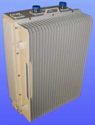
S8L-RRH800L1
Sep 09, 2011800MHz 2x50W RRH RF101017
Equipment Class
AMP - Amplifier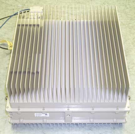
S8L-RRH700L1
Jun 21, 2010Remote Radio Head RRH 2x40W 700MHz RF101002
Equipment Class
TNB - Licensed Non-Broadcast Station Transmitter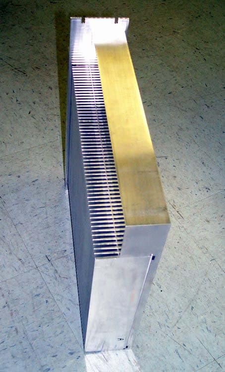
S8L-100978MCPA
Apr 01, 20081960 CDMA Multiple Carrier Power AmplifierRF100978
Equipment Class
AMP - Amplifier
S8L-OBEMICRO1
Mar 30, 2008OneBase Micro Cabinet Cell Extender OBE-1900-2411
Equipment Class
AMP - Amplifier