S8L-100978MCPA1960 CDMA Multiple Carrier Power AmplifierRF100978
Andrew Corporation, Base Station Subsystems Group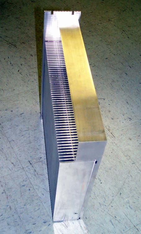
Click to zoom
Application Details
- Equipment Class
- AMP - Amplifier
- Date of Grant
- Apr 01, 2008
- Application Purpose
- Original Equipment
- Date of Application
- Apr 01, 2008
- Equipment Note
- 1960 CDMA Multiple Carrier Power AmplifierRF100978
- Frequency Range
- 1930.00000000 - 1990.00000000
- Country
- United States
Documents & Files
Document Text
Text extracted from the exhibit documents filed with the FCC. Open a document above to read the original.
Users Manual
Andrew Corporation Proprietary – Use pursuant to Company Instruction 1 of 8 1960 CDMA Multiple Carrier Power Amplifier Model: RF100978 Operation Instruction Date: Mar 19, 2008 Version. 1.1 Ref# FCC ID S8L-100978MCPA Andrew Corporation Proprietary – Use pursuant to Company Instruction 2 of 8 Introduction This document presents description of the Andrew Corporation 1960 CDMA Band MCPA (Multi-Carrier Power Amplifier) amplifier. The MCPA amplifier is a high power, RF amplifier intended to provide signal amplification and conditioning. The MCPA amplifier is compatible with CDMA air interfaces operating in U.S. domestic cell sites where FCC compliance is mandatory. The 1960 CDMA band (1930 MHz to 1990 MHz) RF power amplifier is capable of amplifying multiple carriers to a composite power level of 75 Watts. MCPA Specifications The RF100978 provides linear amplification of multi-carrier signals in the CDMA frequency band. The specifications are: Parameter Specification Operating RF Band 1930MHz – 1990MHz Instantaneous BW 15MHz Input DC Power +24 VDC, nominal DC voltage input range +18VDC to +30VDC Rated Output Power @ ≥ 18 to 30 VDC input 75W composite average Rated Power per Carrier 37.5W (2 carriers) 25W (3 carriers) DC-RF Efficiency >27%, rated output power, nominal input voltage @ 25°C Input signal type CDMA (IS-95) Physical dimensions 16.1” (H) x 3.54” (W) x 15.7”(D) Weight 35lbs Cooling technique External fan tray or shelf Temperature Range -5°C to +55°C operational Table 1 MCPA Specifications Andrew Corporation Proprietary – Use pursuant to Company Instruction 3 of 8 The amplifier has been designed to support an instantaneous bandwidth of 15 MHz. Multiple carriers may be placed within a continuous 15 MHz span in the CDMA band and the product shall meet specified performance marks. The amplifier has a nominal gain of 47.5 dB. The MCPA is designed to meet IS-95 specifications over frequency, temperature (-5°C to +55°C), and power level (up to a maximum of 75W RF output power). Functional Blocks: The 1960 CDMA MCPA is comprised of the following functional areas: - Predistortion Circuit - Main amplifier Stage - Power conversion and conditioning circuit - Controller circuit - Communications circuit Inputs and Outputs: The amplifier is powered from a DC supply voltage which can range from +18V to +30V. The DC power is brought into the amplifier through a D-Sub connector located on the front faceplate of the amplifier. A second D-Sub connector located on the amplifier front faceplate is used for RS-485 communication. This connector is used for amplifier configuration, monitoring and alarms. Alarms and operating state are communicated to the outside world through the RS-485 communications bus and a visible bi-color LED located on the amplifier front faceplate. The RF signal is brought into the amplifier through one SMA type connector located on the front faceplate of the amplifier. The amplifier RF signal is brought out of the amplifier through a N type connector located on front faceplate of the amplifier Control System: A microprocessor controller is used to control the amplifier alarm system, control environmental compensation of the amplifier, and to maintain a linearization solution for the predistortion circuit. Andrew Corporation Proprietary – Use pursuant to Company Instruction 4 of 8 Figure 1 RF100978 MCPA Front Panel Figure 2 RF100978 MCPA Back Panel Figure 3 RF100978 MCPA Top & Bottom Panels Andrew Corporation Proprietary – Use pursuant to Company Instruction 5 of 8 Figure 4 RF100978 MCPA Side Panels Andrew Corporation Proprietary – Use pursuant to Company Instruction 6 of 8 The following table is a summary of detailed alarms within the MCPA. The alarms are mapped to front panel LED behavior, as indicated. Additionally, the alarms are available at the D-Sub connector at on the front faceplate of the MCPA. Condition Alarm Type Description LED Color Initial Power On, no alarms - - Red Gain Control Minor Automatic Gain Control Loop out of specification Green Linearization Minor Output Inter-modulation Products are out of specification Green High Temperature Warning Minor High Temperature Warning Green DC voltage regulation Minor DC Voltage regulation out of range Warning Green High DC power consumption Minor High DC Power Consumption Warning Green Partial Main Amp Failure Minor Partial failure within RF chain, RF output is backed off Green Temperature Overload Major Overload Temperature threshold reached. Unit will shutdown Red DC/DC converter Shutdown Major Failure within DC/DC converter. Unit will shutdown Red DC Power Consumption Overload Major Overload DC Power Consumption. Unit will shutdown Red Table 2 Alarm mapping for MCPA Note 1: During a Minor Alarm event, RF output is enabled, however, the product may be out of specification. Minor Alarms are recoverable. Note 2: During a Major Alarm event, the unit will shutdown for self-protection. Major Alarms are non-recoverable and require a Reset or cycling of the power switch Note 3: Details as to the specific alarm event are retrieved through the front panel RS- 485 interface. Andrew Corporation Proprietary – Use pursuant to Company Instruction 7 of 8 The following table shows the pin out for the D-sub connector including the alarm pins. Signal Description Pin Number Manual Control Control ON/OFF 1 GND Ground 2 PA-Enable-Actif + Control 3 PA-Enable-Actif - Control 4 PA_Presence_Reset Towards Micro Controller 5 GND_Presence_Reset Ground 6 Reserved Not allowed for the MCPA 7 GND Ground 8 Reserved Not allowed for the MCPA 9 Reserved Not allowed for the MCPA 10 GND Ground 11 Reserved Not allowed for the MCPA 12 Red LED LED 13 UART TX + (TRM to MCPA) Exchanged Information 14 UART TX - (TRM to MCPA) Exchanged Information 15 Reserved Not allowed for the MCPA 16 UART RX + (MCPA to TRM) Exchanged Information 17 UART RX - (MCPA to TRM) Exchanged Information 18 GND Ground 19-24 Green LED LED 25 Table 3: Pin out for D-Sub connector Andrew Corporati…
Text truncated - open the document above for the full version.
External Photos
EUT: 1960 CDMA Multiple Carrier Power Amplifier Model: RF100978 Report Number: 0048-080310-01 Page 51 Advanced Compliance Laboratory, Inc. 6 Randolph Way, Hillsborough, NJ 08844, Tel: (908) 927 9288 RF100978 Front EUT: 1960 CDMA Multiple Carrier Power Amplifier Model: RF100978 Report Number: 0048-080310-01 Page 52 Advanced Compliance Laboratory, Inc. 6 Randolph Way, Hillsborough, NJ 08844, Tel: (908) 927 9288 RF100978 Rear
ID Label/Location Info
EUT: 1960 CDMA Multiple Carrier Power Amplifier Model: RF100978 Report Number: 0048-080310-01 Page 44 Advanced Compliance Laboratory, Inc. 6 Randolph Way, Hillsborough, NJ 08844, Tel: (908) 927 9288 Section 9. FCC ID Labeling FCC ID Label (The statement may be shown in its User Manual) FCC Label Location (back of EUT) FCC ID: S8L-100978MCPA This device complies with Part 2, 15 & 24 of the FCC Rules. Operation is subject to the following two conditions: (1) this device may not cause harmful interference. an d (2) this device must accept any interference received, including interference that may cause undesire d FCC ID Label
RF Exposure Info
EUT: 1960 CDMA Multiple Carrier Power Amplifier Model: RF100978 Report Number: 0048-080310-01 Page 45 Advanced Compliance Laboratory, Inc. 6 Randolph Way, Hillsborough, NJ 08844, Tel: (908) 927 9288 Section 10. Maximum Permissible Exposure MPE estimate is given per 2.1091 of FCC Rules: Calculation Equation: S d GP 20 10 282.0 + ×= Where, P--max. Output Power, G—Antenna Gain and S—Power Density Factor from §1.1310. Plug all three items into the equation, and yields, Power Density MPE Limit (mW/ cm 2 ) Output Power (dBm) Server Antenna Gain (dBi) Donor Antenna Gain (dBi) Server MPE Distance (cm) Donor MPE Distance (cm) NOTE: For mobile or fixed location transmitters, the minimum separation distance is 20 cm, even if calculations indicate that the MPE distance would be less. N/A FOR THIS CASE ----AMPLIFIER ONLY, NO ATENNNA PRESENT.
Test Report
Electromagnetic Emission Compliance Test Report Equipment Under Test (EUT) 1960 CDMA Multiple Carrier Power Amplifier RF100978 Applicant Andrew Corporation In Accordance With FCC Part 24, Subpart E Test by Advanced Compliance Laboratory, Inc. 6 Randolph Way Hillsborough, New Jersey 08844 Authorized by Wei Li Lab Manager Signature Date March 21,2008 AC Lab Report Number 0048-080310-01 The test result in this report is supported and covered by the NVLAP accreditation. Lab Code:200101-0 Advanced Compliance Laboratory 6 Randolph Way Hillsborough, NJ 08844 Tel: (908) 927 9288 Fax: (908) 927 0728 EUT: 1960 CDMA Multiple Carrier Power Amplifier Model: RF100978 Report Number: 0048-080310-01 Page 2 Advanced Compliance Laboratory, Inc. 6 Randolph Way, Hillsborough, NJ 08844, Tel: (908) 927 9288 Index Section 1. Summary of Test Results....................................................................... 3 Section 2. General Equipment Specification......................................................... 5 Section 3. RF Output Power....................................................................................... 7 Section 4. Occupied Bandwidth.............................................................................. 11 Section 5. Spurious Emissions at Antenna Terminals..................................... 19 Section 6. Field Strength of Spurious................................................................... 35 Section 7. Frequency Stability................................................................................ 41 Section 8. Test Equipment List............................................................................... 43 Section 9. FCC ID Labeling....................................................................................... 44 Section 10. Maximum Permissible Exposure...................................................... 45 Section 11. Setup Photos......................................................................................... 46 Section 12. EUT Photos............................................................................................. 50 EUT: 1960 CDMA Multiple Carrier Power Amplifier Model: RF100978 Report Number: 0048-080310-01 Page 3 Advanced Compliance Laboratory, Inc. 6 Randolph Way, Hillsborough, NJ 08844, Tel: (908) 927 9288 Section 1. Summary of Test Results Manufacturer: Andrew Corporation Model No.: 1960 CDMA Multiple Carrier Power Amplifier RF100978 S/N: PT004 General: All measurements are traceable to national standards These tests were conducted on a sample of the equipment for the purpose of demonstrating compliance with Part 24, Subpart E. New Submission Production Unit Class II Permissive Change Pre-Production Unit THIS TEST REPORT RELATES ONLY TO THE ITEM(S) TESTED. THE FOLLOWING DEVIATIONS FROM, ADDITIONS TO, OR EXCLUSIONS FROM THE TEST SPECIFICATIONS HAVE BEEN MADE. “See Summary of Test Data” NVLAP LAB CODE: 200101-0 Advance Compliance Laboratory, Inc. authorizes the above named company to reproduce this report provided it is reproduced in its entirety and for use by the company’s employees only. Any use which a third party makes of this report, or any reliance on or decisions to be made based on it, are the responsibility of such third parties. Advance Compliance Laboratory, Inc. accepts no responsibility for damages, if any, suffered by any third party as a result of decisions made or actions based on this report. This report applies only to the items tested. EUT: 1960 CDMA Multiple Carrier Power Amplifier Model: RF100978 Report Number: 0048-080310-01 Page 4 Advanced Compliance Laboratory, Inc. 6 Randolph Way, Hillsborough, NJ 08844, Tel: (908) 927 9288 Summary of Test Data 22.913(a) 500W ERP N/A* RF Power Output 24.232(a) 100W EIRP Complies** Occupied Bandwidth (Voice & SAT) 2.1049(i) Mask N/A* Occupies Bandwidth (Wideband Data) 2.1049(i) Mask N/A* Occupied Bandwidth (Digital) 2.1049(i) Mask Complies 22.917 -13 dBm N/A* Spurious Emissions at Antenna Terminals 24.238 -13 dBm Complies 22.917 -13 dBm N/A* Field Strength of Spurious Emissions 24.238 -13 dBm E.I.R.P. Complies 22.355 1.5 ppm N/A* Frequency Stability 24.235 0.05 ppm N/A* * These items are NOT applied to the EUT. ** See page 10. The estimated uncertainty of the test result is given as following. The method of uncertainty calculation is provided in Advanced Compliance Lab. Doc. No. 0048-01-01. Prob. Dist.Uncertainty(dB) Uncertainty(dB) Uncertainty(dB) 30-1000MHz 1-6.5GHz Conducted Combined Std. Uncertainty u c norm. ±2.36 ±2.99 ±1.83 Wei Li Date: March 21, 2008 Lab Manager Advanced Compliance Lab EUT: 1960 CDMA Multiple Carrier Power Amplifier Model: RF100978 Report Number: 0048-080310-01 Page 5 Advanced Compliance Laboratory, Inc. 6 Randolph Way, Hillsborough, NJ 08844, Tel: (908) 927 9288 Section 2. General Equipment Specification Supply Voltage 27V(+18V to +30V) Cellular N/A Frequency Range PCS DL/ 1930 – 1960 MHz Modulation CDMA WCDMA GSM EDGE TDMA Type of Emissions F9W F9W GXW G7W DXW Rated Power 75W average Composite Operating Power 37.5W/carrier for 2 Carrier CDMA 25W/carrier for 3 Carrier CDMA Output Impedance 50ohm F1-F1 F1-F2 N/A Frequency Translation Software Duplexer Change Full Band Coverage DC voltages and DC currents per 2.1033(c)(8) The input supply to the transmitter was set at 27 Volts DC. The RF power output was measured with the indicated voltage and current applied into the final RF amplifying device(s). RF100978 Amplifier RF Output, DC Current and RF Input Power are all average values. Measured Rated RF output: 48.75dBm ( 75W) Measured DC voltage: 27.0V Measured DC current: 12.1A. Measured Minimum RF output: 15.9dBm (38mW) Measured DC voltage: 27.0V Measured DC current: 2.98A EUT: 1960 CDMA Multiple Carrier Power Amplifier Model: RF100978 Report Number: 0048-080310-01 Page 6 Advanced Compliance Laboratory, Inc. 6 Randolph Way, Hillsborough, NJ 08844, Tel: (908) 927 9288 Tune-up procedure per 2.1033(c) (9) There are no user accessible adjustments…
Text truncated - open the document above for the full version.
Test Setup Photos
EUT: 1960 CDMA Multiple Carrier Power Amplifier Model: RF100978 Report Number: 0048-080310-01 Page 46 Advanced Compliance Laboratory, Inc. 6 Randolph Way, Hillsborough, NJ 08844, Tel: (908) 927 9288 Section 11. Setup Photos RF Output Power EUT: 1960 CDMA Multiple Carrier Power Amplifier Model: RF100978 Report Number: 0048-080310-01 Page 47 Advanced Compliance Laboratory, Inc. 6 Randolph Way, Hillsborough, NJ 08844, Tel: (908) 927 9288 Spurious Emissions at Antenna Terminal EUT: 1960 CDMA Multiple Carrier Power Amplifier Model: RF100978 Report Number: 0048-080310-01 Page 48 Advanced Compliance Laboratory, Inc. 6 Randolph Way, Hillsborough, NJ 08844, Tel: (908) 927 9288 Occupied Bandwidth EUT: 1960 CDMA Multiple Carrier Power Amplifier Model: RF100978 Report Number: 0048-080310-01 Page 49 Advanced Compliance Laboratory, Inc. 6 Randolph Way, Hillsborough, NJ 08844, Tel: (908) 927 9288 Field Strength of Spurious
Contact Information
Applicant
Gerald Reynolds(Director, Quality)
Technical Contact
Advanced Compliance LabWei Li
[email protected]9089279288
6 Randolph Way · Hillsborough · United States
Non-Technical Contact
Advanced Compliance LabWei Li
[email protected]9089279288
Test Firm
Advanced Compliance LaboratoryWei Li
Technical Specifications
| # | Rule Parts | Frequency Range | Power Output | Emission | Tolerance |
|---|---|---|---|---|---|
| 1 | 24E | 1.93 GHz - 1.99 GHz | 75 W | F9W | Amp |
Other Applications from Andrew Corporation, Base Station Subsystems Group

S8L-AA190045
Jul 17, 2013RRH 2x45W 1900MHz AA190045 RF151032
Equipment Class
PCB - PCS Licensed Transmitter
S8L-RRH800L1
Sep 09, 2011800MHz 2x50W RRH RF101017
Equipment Class
AMP - Amplifier
S8L-RRH700L1
Jun 21, 2010Remote Radio Head RRH 2x40W 700MHz RF101002
Equipment Class
TNB - Licensed Non-Broadcast Station Transmitter
S8L-OBEMICRO1
Mar 30, 2008OneBase Micro Cabinet Cell Extender OBE-1900-2411
Equipment Class
AMP - Amplifier
S8L-100595HPRM
Feb 22, 2007HPRM850 Amplifier RF100595/NTN065JA
Equipment Class
AMP - Amplifier