S9PIS440Wireless Security Sensor
LifeShield, Inc.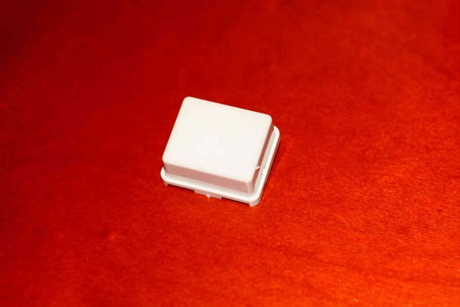
Click to zoom
Application Details
- Equipment Class
- DSR - Part 15 Remote Control/Security Device Transceiver
- Date of Grant
- Apr 05, 2006
- Application Purpose
- Original Equipment
- Date of Application
- Apr 05, 2006
- Equipment Note
- Wireless Security Sensor
- Frequency Range
- 345.00000000 - 345.00000000
- Company
- LifeShield, Inc.
- Country
- United States
Documents & Files
Document Text
Text extracted from the exhibit documents filed with the FCC. Open a document above to read the original.
Users Manual
BHS-i100 Installation and Programming Reference 2/22/06 Draft BHS-i100 Installation and Programming Instructions 2 1 Regulatory Notices ...........................................................4 1.1 FCC Rules Part 15.......................................................4 1.2 ACTA Part 68...............................................................4 2 InGrid Component Installation and Registration ...............5 2.1 Components.................................................................5 2.2 Maximum System Capacity .........................................5 2.3 Wireless Communications Range................................5 2.4 Terminology .................................................................5 2.5 Installation/Registration Process..................................5 2.6 Install Keypads.............................................................6 2.6.1 Wiring & Mounting Keypads ..................................6 2.6.2 Wire The Power Supply.........................................6 2.6.3 Install The Battery .................................................7 2.6.4 Cover Unused Emergency Keys ...........................7 2.7 Install Grid Extenders...................................................7 2.7.1 Installation Guidelines ...........................................7 2.7.2 Install The Battery .................................................7 2.7.3 Mounting................................................................7 2.8 Install The RJ31X / RJ38X...........................................8 2.8.1 Wire The RJ31X Jack As Shown: .........................8 2.8.2 Wire The RJ38X Jack As Shown: .........................8 2.9 Register Grid Extenders...............................................9 2.9.1 Cross Registration .................................................9 2.9.2 Set First Keypad To Master...................................9 2.9.3 Learn The Programmer .........................................9 2.9.4 Learn Additional Keypads ...................................10 2.9.5 Learn Signal Extender(s).....................................10 2.9.6 Resetting A GE To Factory Default .....................10 2.9.7 Registration Troubleshooting ..............................10 2.10 Install/Learn InGrid Sensors ......................................11 2.10.1 Install Mounting Clip ............................................11 2.10.2 Install/Learn The Sensor .....................................11 2.10.3 Troubleshooting Sensor Registration ..................11 2.10.4 Resetting A Sensor To Factory Default...............12 2.11 Install/Learn Auxiliary Sirens......................................12 2.11.1 Install The Auxiliary Siren ....................................12 2.11.2 Learn The Auxiliary Siren ....................................12 2.12 Install/Learn Ademco Transmitters ............................13 2.12.1 Install The Transmitter.........................................13 2.12.2 Learn The Transmitter .........................................13 2.13 Supervision ................................................................14 2.14 Battery Life Indication ................................................14 2.15 Learn Key Fob ...........................................................14 3 Programming ..................................................................15 3.1 Getting Started...........................................................15 3.1.1 Power Up The Programmer ................................15 3.1.2 Registration Overview .........................................15 3.1.3 Register the Programmer ....................................15 3.1.4 Home Menu .........................................................15 3.1.5 Menu Programming Terminology ........................15 3.2 Using The Programmer..............................................16 3.2.1 Navigational And Data-Entry Modes ...................16 3.2.2 Key Functions: Navigational Mode......................16 3.2.3 Key Functions: Data-Entry Mode ........................16 3.2.4 Entering Data ......................................................17 3.2.5 Entry Errors .........................................................17 3.3 Organization Of Menu Programming .........................19 3.3.1 Programming Tree ..............................................19 3.3.2 Logical Programming Groups..............................19 3.3.3 Standard versus Advanced Programming...........19 3.4 Numbering Conventions ............................................19 3.5 Programming Options ................................................20 3.5.1 Home Menu Option 1: Set Defaults....................20 3.5.2 Home Menu Option 2: Learn Devices .................20 3.5.3 Home Menu Option 3: Standard Menu................21 3.5.4 Home Menu Option 4: Advanced Menu ..............23 3.5.5 Home Menu Option 5: Test Menu .......................28 3.5.6 Home Menu Option 6: Replace Hardware ..........28 3.5.7 Home Menu Option 7: Upload Configuration...... 28 3.5.8 Home Menu Option 8: Browse Events ............... 28 3.5.9 Home Menu Option 9: Diagnostics ..................... 28 3.5.10 Home Menu Option 10: Programmer Battery Status 28 3.5.11 Home Menu Option 11: Set Poweroff Time ........ 28 3.5.12 Home Menu Option 12: Set Backlitght Time ...... 28 3.6 Programmable Options Lists..................................... 29 3.6.1 List A: Zone types ............................................... 29 3.6.2 List B: Output patterns ........................................ 29 3.6.3 Automatic Zone Configurations .......................... 29 3.7 Remote Programming ............................................... 30 3.8 Shortcut Programming .............................................. 30 4 System Testing And Maintenance ................................. 31 4.1 System ...................................................................... 31 4.1.1 Installer Testing .................................................. 31 4.1.2 Pre-Test System Reporting…
Text truncated - open the document above for the full version.
Users Manual
ii BrinksKeyPadPrinterSprd.2.22.06 2/22/06 3:06 PM Page 1 UDZZ01250ZZ(0) PRINTED IN CHINA. User’s Manual for the Brinks Home Security System by InGrid ® Model # BHS i 100 BrinksKeyPadPrinterSprd.2.22.06 2/22/06 3:06 PM Page 2 49 Br ink’s Home Security is a Registered Trademark of the Brink’s Network, Inc. InGrid is a Trademark of InGrid, Inc. All other trademarks in this manual are the proper ties of their respective owners . SAVE THESE INSTRUCTIONS! Place the following message in the “Important Notices” Section at the end of the manual. Note: please include the “recycle symbol” found below adjacent to the text. Rechargeable Nickel-Metal-Hydride Batteries Must Be Recycled or Disposed of Properly NI-MH 2004K BrinksKeyPadPrinterSprd.2.22.06 2/22/06 3:06 PM Page 4 48 Rechargeable Nickel-Metal-Hydride Battery Warning • This equipment contains a rechargeable Nickel-Metal- Hydride battery. • Nickel is a chemical known to state of California to cause cancer. • The rechargeable Nickel-Metal-Hydride battery contained in this equipment may explode if disposed of in a fire. • Do not short-circuit the battery. • Do not charge the rechargeable Nickel-Metal-Hydride battery used in this equipment in any charger other than the one designed to charge this battery as specified in the owner's manual. Using another charger may damage the battery or cause the battery to explode. Additional Battery Safety Precautions Caution! To reduce the risk of fire or injury to persons by the battery, read and follow these instructions: 1. Use only the Uniden battery pack specified in the owner's manual. 2.Do not dispose of the battery pack in a fire.The cell may explode.Check the Nickel Metal Hydride battery disposal package insert for disposal instructions. 3.Do not open or mutilate the battery pack.Released electrolyte is corrosive and may cause damage to the eyes or skin. It may be toxic if swallowed. 4. Exercise care in handling the battery in order not to short the battery with conducting materials such as rings, bracelets, and keys. The battery or conductor may overheat and cause burns. 5. Charge the battery pack provided with or identified for use with this product only in accordance with the instructions and limitations specified in the owners manual provided for this product. 6. Observe proper polarity orientation between the battery pack and battery charger. i Consumer Information FCC Notices This device complies with Part 15 of the FCC Rules. Operation is subject to the following two conditions: (1) This device may not cause harmful interference, and (2) this device must accept an y interference received, including interference that may cause undesired operation. FCC Part 15 Class B This equipment has been tested and found to comply with the limits for a Class B digital device, pursuant to Part 15 of the FCC Rules. These limits are designed to provide reasonable protection against harmful interference in a residential installation. This equipment generates, uses and can radiate radio frequency energy and, if not installed and used in accordance with the instructions, may cause harmful interference to radio communications. However, there is no guarantee that interference will not occur in a particular installation. If interference generated by this unit is suspected, call Brink’s Customer Care at 1-800-445-0872. If this equipment does cause har mful interference to radio or television reception, which can be determined by turning the equipment off and on, the user is encouraged to try to correct the interference by one or more of the following measures: • Re-orient the radio/television antenna; • Move the television or receiver away from the unit. • Plug the unit and the TV/radio receiver into different outlets, i.e. not on the same circuit breaker. • Contact Brinks Home Security or an experienced TV/Radio technician for additional suggestions. • Review additional instructions on www.mybrinks.com. Part Number SE 430; FCC ID: S9PSE430 P ar t Number BK 410; FCC ID: S9PBK410 Part Number IS440; FCC ID: S9PIS440 Part Number BS450; FCC ID: S9PBS450 A CT A Part 68 This equipment complies with P art 68 of the FCC rules and requirements adopted by the ACTA. On the outside of this equipment is a label that contains , among other information, a product identifier in the f or mat US:AAEQ##TXXXX. If requested, this n umber must be provided to the telephone company The REN (Ringer Equivalence Number) is used to determine the number of devices that ma y be connected to a telephone line . Excessive RENs on a telephone line may result in the de vices not r inging in response to an incoming call. In most b ut not all areas , the sum of RENs should not exceed five (5.0). To be certain of the number of devices that may be connected to a line , as deter mined by the total RENs, contact the local telephone company. For products approved after July 23, 2001, the REN for this product is part of the product identifier that has the f ormat US:AAAEQ##TXXXX. The digits represented by ## are the REN without a decimal point (e .g. 03 is a REN of 0.3). F or ear lier products , the REN is separ ately shown on the label. P ar t Number SE 430; ACTA Registration Number: US:S9PAL01BSE430 BrinksKeyPadPrinterSprd.2.22.06 2/22/06 3:06 PM Page 6 This equipment is designated to be connected to the telephone network or premises wiring using a compatible modular jack (RJ31X) which is part 68 compliant. A plug and jack used to connect this equipment to the premises wiring and telephone network must comply with the applicable FCC Part 68 rules and requirements adopted by the ACTA. A compliant telephone cord and modular plug is provided with this product. It is designed to be connected to a compatible modular jack that is also compliant. See installation instructions for details. If this equipment (Model BHS i-100) causes harm to the telephone network, the telephone company will notify you in advance that temporary discontinuance of service may be required…
Text truncated - open the document above for the full version.
External Photos
Exhibit 3 (Page 1 of 1) External Photos IS440 Door/Window Sensor
ID Label/Location Info
Exhibit 1 (Page 1 of 1) Label Detail
Internal Photos
Exhibit 9 (Page 1 of 2) Internal Photographs IS440 Door/Window Sensor Exhibit 9 (Page 2 of 2) Internal Photographs IS440 Door/Window Sensor
Test Report
FCC Part 15 Subpart C, 15.231 : February 2005 Test Report: 6W62153 Applicant: Ingrid Inc. 920 Cassatt Rd., Suite 220 Berwyn, PA 19312 Apparatus: Ingrid Door Window Sensor IS440 FCC ID: S9PIS440 In Accordance With: FCC Part 15 Subpart C, 15.231 Periodic operation in the band 40.66-40.70MHz and above 70 MHz. Tested By: Nemko Canada Inc. 303 River Road Ottawa, Ontario K1V 1H2 Authorized By: Jason Nixon, Telecom Specialist Date: April 4, 2006 Total Number of Pages: 19 Nemko Canada Inc. REPORT SUMMARY Report Number:6W62153 FCC ID: S9PIS440 Specification: FCC Part 15 Subpart C, 15.231 Page 2 of 19 Report Summary These tests were conducted on a sample of the equipment for the purpose of demonstrating compliance with Part 15, Subpart C. Radiated tests were conducted in accordance with ANSI C63.4-2003. Radiated emissions are made on an open area test site. A description of the test facility is on file with the FCC. The assessment summary is as follows: Apparatus Assessed: Ingrid Door Window Sensor IS440 Specification: FCC Part 15 Subpart C, 15.231 Compliance Status: Complies Exclusions: None Non-compliances: None Report Release History: Original Release Author: Xu Jin, Wireless Specialist Note that the results contained in this report relate only to the items tested and were obtained in the period between the date of initial receipt of samples and the date of issue of the report. This test report has been completed in accordance with the requirements of ISO/IEC 17025. Nemko Canada Inc. authorizes the applicant to reproduce this report provided it is reproduced in its entirety and for use by the company’s employees only. Any use which a third party makes of this report, or any reliance on or decisions to be made based on it, are the responsibility of such third parties. Nemko Canada Inc. accepts no responsibility for damages, if any, suffered by any third party as a result of decisions made or actions based on this report. Nemko Canada Inc. REPORT SUMMARY Report Number:6W62153 FCC ID: S9PIS440 Specification: FCC Part 15 Subpart C, 15.231 Page 3 of 19 TABLE OF CONTENTS Report Summary......................................................................................................................................... 2 Section 1 : Equipment Under Test............................................................................................................. 4 1.1 Product Identification .................................................................................................................................4 1.2 Samples Submitted for Assessment............................................................................................................4 1.3 Technical Specifications of the EUT ..........................................................................................................5 Section 2 : Test Conditions......................................................................................................................... 6 2.1 Specifications .............................................................................................................................................6 2.2 Deviations From Laboratory Test Procedures ............................................................................................6 2.3 Test Environment .......................................................................................................................................6 2.4 Test Equipment...........................................................................................................................................6 Section 3 : Observations ............................................................................................................................. 7 3.1 Modifications Performed During Assessment ............................................................................................7 3.2 Record Of Technical Judgements ...............................................................................................................7 3.3 EUT Parameters Affecting Compliance .....................................................................................................7 3.4 Test Deleted................................................................................................................................................7 3.5 Additional Observations .............................................................................................................................7 Section 4: Results Summary ...................................................................................................................... 8 Appendix A: Test Results ......................................................................................................................... 10 Appendix B : Setup Photographs ............................................................................................................ 18 Appendix C: Block Diagram of Test Setups ........................................................................................... 19 Nemko Canada Inc. SECTION 1 : EQUIPMENT UNDER TEST Report Number:6W62153 FCC ID: S9PIS440 Specification: FCC Part 15 Subpart C, 15.231 Page 4 of 19 Section 1 : Equipment Under Test 1.1 Product Identification The Equipment Under Test was identified as follows: Ingrid Door Window Sensor IS440 1.2 Samples Submitted for Assessment The following samples of the apparatus have been submitted for type assessment: Sample No. Description Serial No. 1 Ingrid Door Window Sensor IS440 N/A The first samples were received on: Mar 15, 2006 Nemko Canada Inc. SECTION 1 : EQUIPMENT UNDER TEST Report Number:6W62153 FCC ID: S9PIS440 Specification: FCC Part 15 Subpart C, 15.231 Page 5 of 19 1.3 Technical Specifications of the EUT Manufacturer: Ingrid Inc. Operating Frequency: 345MHz Emission Designator: K1D Modulation: ASK Antenna Data: Integral Power Source: Internal battery operated Nemko Canada Inc. SECTION 2 : …
Text truncated - open the document above for the full version.
Test Setup Photos
Spurious Emissions Setup:
Contact Information
Applicant
Louis Stilp(President)
Technical Contact
Ingrid, Inc.Ed Mansfield
[email protected]484 913 1407
920 Cassatt Road · Berwyn, Pennsylvania · United States
Non-Technical Contact
Ingrid, Inc.William Brown
[email protected]484 913 1421
Test Firm
Nemko Canada Inc. (Ottawa)Charles Neal
Technical Specifications
| # | Rule Parts | Frequency Range | Power Output |
|---|---|---|---|
| 1 | 15.231 | 345 MHz - 345 MHz | - |
Other Applications from LifeShield, Inc.
S9PSDC1001
Nov 14, 2012wireless sensor
Equipment Class
DSC - Part 15 Security/Remote Control Transmitter
S9PBSC1001
Mar 21, 2011BSC1001 Base Unit
Equipment Class
DSS - Part 15 Spread Spectrum Transmitter
S9PSNC1010
Feb 09, 2011Wireless Security Sensor
Equipment Class
DSC - Part 15 Security/Remote Control Transmitter
S9PHSC1000
Aug 07, 2007Wireless Grid Controller
Equipment Class
DSS - Part 15 Spread Spectrum Transmitter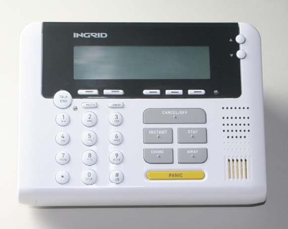
S9PKPC1000
Jun 19, 2007Wireless Security System Keypad
Equipment Class
DSS - Part 15 Spread Spectrum Transmitter