S9PSS470Siren-Strobe
LifeShield, Inc.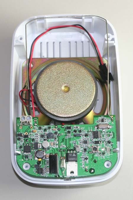
Click to zoom
Application Details
- Equipment Class
- DSR - Part 15 Remote Control/Security Device Transceiver
- Date of Grant
- Oct 22, 2006
- Application Purpose
- Original Equipment
- Date of Application
- Oct 22, 2006
- Equipment Note
- Siren-Strobe
- Frequency Range
- 345.00000000 - 345.00000000
- Company
- LifeShield, Inc.
- Country
- United States
Documents & Files
Document Text
Text extracted from the exhibit documents filed with the FCC. Open a document above to read the original.
Users Manual
Installation and Programming Guide SS470 Auxiliary Siren-Strobe SSC1000 Auxiliary Siren-Strobe October 13, 2006 Draft BHS-i100 Installation and Programming Instructions 1 egulatory Notices...........................................................3 R 1.1 FCC Rules Part 15.......................................................3 2 Grid Component Installation and Registration...............4 In 2.1 Components.................................................................4 2.2 Maximum System Capacity.........................................4 2.3 Wireless Communications Range................................4 2.4 Install the SS470 Siren-Strobe....................................4 2.4.1 Wiring & Mounting the Siren-Strobe......................4 2.4.2 Wire the Power Supply..........................................5 2.4.3 Install the Battery...................................................5 2.5 Install/Learn Auxiliary Sirens........................................5 2.5.1 Learn The Auxiliary Siren......................................6 2.5.2 Replacing Auxiliary Siren......................................6 2.5.3 Auxiliary Siren Does Not Sound............................6 2.5.4 Setting Options......................................................6 2.5.5 Trouble Messages.................................................7 2 BHS-i100 Installation and Programming Instructions 1 Regulatory Notices 1.1 FCC Rules Part 15 This device complies with Part 15 of the FCC Rules. Operation is subject to the following two conditions: (1) this device may not cause harmful interference, and (2) this device must accept any interference received, including interference that may cause undesired operation. Changes or modifications not expressly approved by InGrid, Inc. can void the user’s authority to operate the equipment. This equipment has been tested and found to comply with the limits for a Class B digital device, pursuant to part 15 of the FCC Rules. These limits are designed to provide reasonable protection against interference in a residential installation. This equipment generates, uses, and can radiate radio frequency energy and, if not installed and used in accordance with the instructions, may cause harmful interference to radio communications. However, there is no guarantee that interference will not occur in a particular installation. If interference generated by this unit is suspected, call Brink’s Customer Care at 1-800-445-0872. If this equipment does cause harmful interference to radio or television reception, which can be determined by turning the equipment off and on, the user is encouraged to try to correct the interference by one or more of the following measures: • Re-orient the radio/television antenna; • Move the television or receiver away from the unit. • Plug the unit and the TV/radio receiver into different outlets, i.e. not on the same circuit breaker. • Contact Brinks Home Security or an experienced TV/Radio technician for additional suggestions. Part Number SS470; FCC ID: S9PSS470 Part Number SSC1000; FCC ID; S9PSS470 3 BHS-i100 Installation and Programming Instructions 2 InGrid Component Installation and Registration Important Note Please read and fully understand the BHS-i100 User’s Manual before reading this manual or attempting to install the system. The User’s Manual describes the system’s features, functions, and user interface requirements in great detail. That information is not repeated in this manual 2.1 Components The SS470 Auxiliary Siren-strobe is designed for residential applications. It is intended to be used as a supplementary audible and visual signaling device when used with the BHS- i100 Home Security System. It communicates using encrypted two-way wireless signals. The only wired connection is power via a plug-in power supply. A BHS-i100 system can contain the following compatible components: Grid Extenders Model Number Brinks Keypad BK410 Grid Extender SE430 Brinks Programmer BP420 InGrid Sensors Model Number Window/Door Sensor IS440 Keychain Remote KF460 Auxiliary Siren SS470 Ademco Transmitters Model Number Glass Break Detector 5853 Motion Detector 5800 Smoke Detector 5808LST Note: Compatibility between models KF460, 5816, and the BP420 has not been evaluated by UL. 2.2 Maximum System Capacity The maximum number of Auxiliary Siren-Strobe devices in a single system is 4. The Auxiliary Siren-Strobe is intended to be used only with the BHS-i100 system. Each BHS-i100 system must contain at least 1 Brinks Keypad and at least 1 Signal Extender to support the addition of a SS470 Auxiliary Siren- Strobe. 2.3 Wireless Communications Range There are two types of wireless communications used in a BHS- i100 system: Grid Extender to Grid Extender – This communication operates at 2.4 GHz. To avoid the potential for conflict with WiFi networks, it is good installation practice to locate any Grid Extender at least 10 feet from a WiFi router that a customer may be using. The Grid Extenders installed in a single customer’s home, garage, and shed work together in a redundant grid network. If you were to draw a circle around all of the Grid Extenders in a single grid network, the maximum diameter of that circle must be less than 300 feet. The InGrid system will ensure installation within the acceptable range. Siren-Strobe to Grid Extender – This communication operates at 345 MHz and 2.4 GHz. Communication from the InGrid SS470 to Grid Extenders is two-way encrypted wireless. SS470’s may communicate to any Grid Extender. The maximum distance from a SS470 to the closest Grid Extender must be less than 30 feet. Proper installation of the Grid Extenders and SS470 is determined by using the Installation and Registration Process. 2.4 Install the SS470 Siren-Strobe The SS470 Siren-Strobe must be mounted in a dry, clean location. The SS470 Auxiliary Siren-Strobe should be wall-mounted at a height that provides the best possible audible and visual alarm signaling. The BHS-i100 supports up to 4…
Text truncated - open the document above for the full version.
External Photos
Exhibit 3 S9PSS470 Ingrid Siren-strobe Exterior Top View Exterior Bottom View Exhibit 3 (page 2) S9PSS470 Ingrid Siren-strobe Mounting Plate
ID Label/Location Info
Exhibit 1 Label Details S9PSS470 Version A Label Location Version B
Internal Photos
Exhibit 9 Ingrid S9PSS470 Interior Photos Bottom View PCB Top View PCB 2400 MHz Antenna 345 MHz Antenna feed point 345 MHz Antenna feed point 2400 MHz Antenna feed point 345 MHz Antenna Exhibit 9 Ingrid SS470 Interior Photos Top View PCB 2400 MHz Antenna 345 MHz Antenna
Test Report
FCC Part 15 Subpart C, 15.231 : June 2006 Test Report: 6W72155.1 Applicant: Ingrid Inc. 920 Cassatt Road Suite 220 Berwyn, PA 19312 Apparatus: SS470 Siren Strobe FCC ID: S9PSS470 In Accordance With: FCC Part 15 Subpart C, 15.231 Periodic operation in the band 40.66-40.70MHz and above 70 MHz. Tested By: Nemko Canada Inc. 303 River Road Ottawa, Ontario K1V 1H2 Authorized By: Jin Xu, wireless Specialist Date: September 27, 2006 Total Number of Pages: 21 Nemko Canada Inc. REPORT SUMMARY Report Number: 6W72155.1 FCC ID: S9PSS470 Specification: FCC Part 15 Subpart C, 15.231 Page 2 of 21 Report Summary These tests were conducted on a sample of the equipment for the purpose of demonstrating compliance with Part 15, Subpart C. Radiated tests were conducted in accordance with ANSI C63.4-2003. Radiated emissions are made on an open area test site. A description of the test facility is on file with the FCC. The assessment summary is as follows: Apparatus Assessed: SS470 Siren Strobe Specification: FCC Part 15 Subpart C, 15.231 Compliance Status: Complies Exclusions: None Non-compliances: None Report Release History: Original Release Author: Jason Nixon, Telecom Specialist Note that the results contained in this report relate only to the items tested and were obtained in the period between the date of initial receipt of samples and the date of issue of the report. This test report has been completed in accordance with the requirements of ISO/IEC 17025. Nemko Canada Inc. authorizes the applicant to reproduce this report provided it is reproduced in its entirety and for use by the company’s employees only. Any use which a third party makes of this report, or any reliance on or decisions to be made based on it, are the responsibility of such third parties. Nemko Canada Inc. accepts no responsibility for damages, if any, suffered by any third party as a result of decisions made or actions based on this report. Nemko Canada Inc. REPORT SUMMARY Report Number: 6W72155.1 FCC ID: S9PSS470 Specification: FCC Part 15 Subpart C, 15.231 Page 3 of 21 TABLE OF CONTENTS Report Summary......................................................................................................................................... 2 Section 1 : Equipment Under Test............................................................................................................. 4 1.1 Product Identification .................................................................................................................................4 1.2 Samples Submitted for Assessment............................................................................................................4 1.3 Theory of Operation ...................................................................................................................................4 1.4 Technical Specifications of the EUT ..........................................................................................................5 1.5 Block Diagram of the EUT.........................................................................................................................5 Section 2 : Test Conditions......................................................................................................................... 6 2.1 Specifications .............................................................................................................................................6 2.2 Deviations From Laboratory Test Procedures ............................................................................................6 2.3 Test Environment .......................................................................................................................................6 2.4 Test Equipment...........................................................................................................................................6 Section 3 : Observations ............................................................................................................................. 7 3.1 Modifications Performed During Assessment ............................................................................................7 3.2 Record Of Technical Judgements ...............................................................................................................7 3.3 EUT Parameters Affecting Compliance .....................................................................................................7 3.4 Test Deleted................................................................................................................................................7 3.5 Additional Observations .............................................................................................................................7 Section 4 : Results Summary ..................................................................................................................... 8 4.1 FCC Part 15 Subpart C : Test Results ........................................................................................................9 Appendix A : Test Results ........................................................................................................................ 10 Clause 15.207(a) Powerline Conducted Emissions .............................................................................................10 Clause 15.209(a) Radiated Emissions within Restricted Bands ..........................................................................13 Clause 15.231(a) Conditions for intentional radiators to comply with periodic operation ..................................14 Clause 15.231(b) Radiated Emissions .................................................................................................................16 Clause 15.231(c) 20dB Bandwidth ......................................................................................................................19 Appendix B : Setup Photographs ......…
Text truncated - open the document above for the full version.
Test Setup Photos
Conducted Emissions Setup: Spurious Emissions Setup:
Contact Information
Applicant
Louis Stilp(President)
Technical Contact
Ingrid Inc.Ed Mansfield
[email protected]484 913 1407
920 Cassat Road · Berwyn, Pennsylvania · United States
Non-Technical Contact
Ingrid Inc.William Brown
[email protected]484 913 1421
Test Firm
Nemko Canada Inc. (Ottawa)Charles Neal
Technical Specifications
| # | Rule Parts | Frequency Range | Power Output |
|---|---|---|---|
| 1 | 15.231 | 345 MHz - 345 MHz | - |
Other Applications from LifeShield, Inc.
S9PSDC1001
Nov 14, 2012wireless sensor
Equipment Class
DSC - Part 15 Security/Remote Control Transmitter
S9PBSC1001
Mar 21, 2011BSC1001 Base Unit
Equipment Class
DSS - Part 15 Spread Spectrum Transmitter
S9PSNC1010
Feb 09, 2011Wireless Security Sensor
Equipment Class
DSC - Part 15 Security/Remote Control Transmitter
S9PHSC1000
Aug 07, 2007Wireless Grid Controller
Equipment Class
DSS - Part 15 Spread Spectrum Transmitter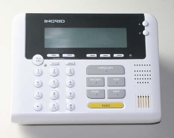
S9PKPC1000
Jun 19, 2007Wireless Security System Keypad
Equipment Class
DSS - Part 15 Spread Spectrum Transmitter