SBDB421TPMS Transmitter
Bridgestone Corporation
Click to zoom
Application Details
- Equipment Class
- DSC - Part 15 Security/Remote Control Transmitter
- Date of Grant
- Jul 05, 2006
- Application Purpose
- Original Equipment
- Date of Application
- Jul 02, 2006
- Equipment Note
- TPMS Transmitter
- Frequency Range
- 315.00000000 - 315.00000000
- Company
- Bridgestone Corporation
- Country
- Japan
Documents & Files
Document Text
Text extracted from the exhibit documents filed with the FCC. Open a document above to read the original.
Users Manual
Tire-Pressure Monitoring System For truck and bus For use only in Europe (model:B422) or U.S.A. (model:B421) Apr. 2006 Base REG Developmen t 2006.04 Base Copyright © 2006 Bridgestone Corporation Manufacturing and Sales Bridgestone Corporation 1-10-1 Kyobashi Chuoku Tokyo 104-8340 http://www.bridgestone.co.jp/ Sensor Operation Guide Notice to user What is a Tire-Pressure Monitoring System ? Tire-pressure monitoring system is an advanced system that measures the tire pressure and temperature with sensors mounted inside the tire and enables vehicle management using the measured data. This product is designed exclusively for trucks and buses. Supported rim size is from 16 to 22.5 inches. This product has two design for use within Europe and USA. It cannot be used other country due to difference in radio wave regulations. Attention for product model number. For Europe......model B422 For USA.......... model B421 Technical knowledge is necessary for sensor installation and removal. Contact shops employing tire mechanic for installation and removal. Be sure to read and understand the content of the operation guide before installing or removing. Keep this guide in a safe place and refer to it as necessary. 1 SAFETY PRECAUTIONS SENSOR INSTALLATION MOUNTING TIRE ON RIM REMOVE THE SENSOR TRANSPORTATION, STORAGE & DISPOSAL TROUBLESHOOTING SERVICE & REPAIR SPECIFICATION INDEX SENSOR WARRANTY INTRODUCTION This guide describes how to use the tire pressure monitoring system sensor (referred hereafter as "this product" or "sensor") designed exclusively for trucks and buses. Please read and understand the content before using. NOTE Installation of this product requires knowledge of vehicle safety and tires. Installation should be performed by a person with such experience. About This Product • By installing this product inside the tire (rim), it can measure the pressure and internal temperature and send the data by radio wave. • A separate hand reader is necessary to read the data after installing this product. Hand reader can be purchased separately from your dealer. Package Content Check that the following items are included in the package. Introduction Sensor x 6 to 12 (depend on the number of tires) Items included in the sensor package Valve mark x 6 to 12 (depend on the number of tires) Mounting band (specified rim size) x 6 to 12 (depend on the number of tires) Mounting band * The operation guide can be obtained separately from your dealer. It is not included with the product. Operation Guide Tire-Pressure Monitoring System For truck and bus For use only in Europe (model:B4 22) or U.S.A. (model:B4 21) Sensor Operation Guide Notice to user What is a Tire-Pressure Monitoring System? Tire-pressure monitoring system is an advanced system that measures the tire pressure and temperature with sensors mounted inside the tire and enables vehicle management using the measured data. This product is designed exclusively for trucks and buses. Supported rim size is from 16 to 22.5 inches. This product has two design for use within Europe and USA. It cannot be used other country due to difference in radio wave regulations. Attention for product model number. For Europe...... model B4 22 For USA.......... model B4 21 Technical knowledge is necessary for sensor installation and removal. Contact shops employing tire mechanic for installation and removal. Be sure to read and understand the content of the operation guide before installing or removing. Keep this guide in a safe place and refer to it as necessary. * Number of packages depend on the part number. * Six mounting bands are contained in one box. The remainder are packaged separately. Mark color for location For Europe: Model No.B422 Color: green For USA: Model No.B421 Color: blue 2 About Tire-Pressure Monitoring System The tire-pressure monitoring system (hereafter referred to as "system" or "this system") is a system that monitors the tire pressure and temperature using sensors mounted inside tires (rim). This system is available as "Hand Reader Type" and "On-Board Type". Purchase the product that is appropriate for your intended use. Hand reader type This system receives the radio wave from the sensor with a portable hand reader. The radio wave from the sensor is received with the vehicle stopped. It cannot be used when moving. <Equipment Configuration> On-board type This system measure and monitors the radio wave from the sensor with a display and warning lamp mounted on the dashboard. When there is a tire problem, the display and warning lamps on the dashboard emit alarms to notify the driver. The tire status can be monitored while moving. <Equipment Configuration> Sensor Hand reader Receiver Sensor Example of installing 4 receivers and 10 sensors Receiver Cable Vehicle power supply ▪BAT ▪IGN ▪GND ECU Display Warning lamp Warning lamp Display ECU Receiver Sensor Install on dashboard Install inside cabi n Install on vehicle or fram e Install inside tire (rim ) 3 SAFETY PRECAUTIONS SENSOR INSTALLATION MOUNTING TIRE ON RIM REMOVE THE SENSOR TRANSPORTATION, STORAGE & DISPOSAL TROUBLESHOOTING SERVICE & REPAIR SPECIFICATION INDEX SENSOR WARRANTY INTRODUCTION Operation Guide Combination The following operation guides must be obtained depending on whether your system is a Hand reader type or On-board type. Read the guide appropriate for your system. Guide Hand reader type On-board type Content Tire-Pressure Monitoring System Sensor Operation Guide (this document) Describes sensor installation, rim installation and removal, and precautions Tire-Pressure Monitoring System On-Board Type Operation Guide Describes the installation, wiring, system setup, and precautions of receiver, display, warning lamp, and ECU Tire-Pressure Monitoring System Display Operation Guide Describes the display operation method and precautions Tire-Pressure Monitoring System Hand Reader Type Operation Guide Describes the hand reader operation method and precautions • This opera…
Text truncated - open the document above for the full version.
External Photos
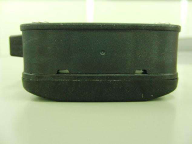
SENSOR_B421 External Photograph TOP View BOTTOM View SIDE(TOP) View SIDE(BOTTOM) View SIDE(LEFT) View SIDE(RIGHT) View
ID Label/Location Info
TPMSEMC022 Label for SENSOR_B421
Internal Photos
SENSOR_B421 Internal photograph TOP View BOTTOM View TOP View BOTTOM View
Test Report
Test report No. : 26IE0253-HO-A Page : 1 of 16 Issued date : June 16, 2006 FCC ID : SBDB421 UL Apex Co., Ltd. Head Office EMC Lab. 4383-326 Asama-cho, Ise-shi, Mie-ken 516-0021 JAPAN Telephone : +81 596 24 8116 Facsimile : +81 596 24 8124 MF060b(14.06.06) RADIO TEST REPORT Test Report No. : 26IE0253-HO-A Applicant : BRIDGESTONE Co., Ltd. Type of Equipment : SENSOR Model No. : B421 Test standard : FCC Part 15 Subpart C Section 15.231:2006 FCC ID : SBDB421 Test Result : Complied 1. This test report shall not be reproduced in full or partial, without the written approval of UL Apex Co., Ltd. 2. The results in this report apply only to the sample tested. 3. This equipment is in compliance with above regulation. 4. The test results in this report are traceable to the national or international standards. Date of test : May 22, 2006 Tested by : Yasuyuki Fukui EMC Services Approved by : Naoki Sakamoto Group Leader of EMC Services Test report No. : 26IE0253-HO-A Page : 2 of 16 Issued date : June 16, 2006 FCC ID : SBDB421 UL Apex Co., Ltd. Head Office EMC Lab. 4383-326 Asama-cho, Ise-shi, Mie-ken 516-0021 JAPAN Telephone : +81 596 24 8116 Facsimile : +81 596 24 8124 MF060b(14.06.06) CONTENTS PAGE SECTION 1: Client information...................................................................................................... 3 SECTION 2: Equipment under test (E.U.T.) ................................................................................. 3 SECTION 3: Test specification, procedures & results .................................................................. 4 SECTION 4: Operation of E.U.T. during testing........................................................................... 7 SECTION 5: Radiated emission (Fundamental and Spurious Emission) ................................... 8 APPENDIX 1: Photographs of test setup........................................................................................ 9 Radiated emission......................................................................................................................................... 9 Worst case position .................................................................................................................................... 10 APPENDIX 2:Test Instruments...................................................................................................... 11 APPENDIX 3: Data of EMI test ..................................................................................................... 12 Radiated Emission (Electric Field Strength of Fundamental and Spurious Emission) ....................... 12 Duty factor calculation .............................................................................................................................. 13 Transmitting and interval ......................................................................................................................... 14 -20dB Bandwidth........................................................................................................................................ 15 99% Occupied Bandwidth......................................................................................................................... 16 Test report No. : 26IE0253-HO-A Page : 3 of 16 Issued date : June 16, 2006 FCC ID : SBDB421 UL Apex Co., Ltd. Head Office EMC Lab. 4383-326 Asama-cho, Ise-shi, Mie-ken 516-0021 JAPAN Telephone : +81 596 24 8116 Facsimile : +81 596 24 8124 MF060b(14.06.06) SECTION 1: Client information Company Name : BRIDGESTONE Co., Ltd. Address : 3-1-1, Ogawahigashi-Cho, Kodaira-Shi, Tokyo, 187-8531 Japan Telephone Number : +81-42-342-6326 Facsimile Number : +81-42-342-6596 Contact Person : Toshihiro Miyazaki SECTION 2: Equipment under test (E.U.T.) 2.1 Identification of E.U.T. Type of Equipment : SENSOR Model No. : B421 Serial No. : 0020DB Rating : DC 3.0V, 0.01A Country of Manufacture : Japan Receipt Date of Sample : May 18, 2006 Condition of EUT : Production model Modification of EUT : No modification by the test lab. 2.2 Product Description Model No: B421 (referred to as the EUT in this report) is the SENSOR. Equipment Type : Transmitter Frequency of Operation : 315.01MHz Type of modulation : FSK Power Control : No ITU code : F1D Antenna Type : Loop Antenna Method of Frequency Generation : Crystal Test report No. : 26IE0253-HO-A Page : 4 of 16 Issued date : June 16, 2006 FCC ID : SBDB421 UL Apex Co., Ltd. Head Office EMC Lab. 4383-326 Asama-cho, Ise-shi, Mie-ken 516-0021 JAPAN Telephone : +81 596 24 8116 Facsimile : +81 596 24 8124 MF060b(14.06.06) SECTION 3: Test specification, procedures & results 3.1 Test Specification Test Specification : FCC Part 15 Subpart C : 2006 Title : FCC 47CFR Part15 Radio Frequency Device Subpart C Intentional Radiators Section 15.231 Periodic operation in the band 40.66 - 40.70MHz and above 70MHz FCC 15.31 (e) This test was performed with the New Battery (DC 3.0V) and the constant voltage was supplied to the EUT during the tests. Therefore, the EUT complies with the requirement. FCC Part 15.203 Antenna requirement It is impossible for end users to replace the antenna, because the antenna is mounted inside of the EUT. Therefore, the equipment complies with the antenna requirement of Section 15.203. Test report No. : 26IE0253-HO-A Page : 5 of 16 Issued date : June 16, 2006 FCC ID : SBDB421 UL Apex Co., Ltd. Head Office EMC Lab. 4383-326 Asama-cho, Ise-shi, Mie-ken 516-0021 JAPAN Telephone : +81 596 24 8116 Facsimile : +81 596 24 8124 MF060b(14.06.06) 3.2 Procedures and results No. Item Test Procedure Specification Deviation Worst marginResults 1 Transmitting time and Interval ANSI C63.4:2003 13. Measurement of intentional radiators Section 15.231(e) N/A - Complied 2 Electric Field Strength of Fundamental Emission ANSI C63.4:2003 13. Measurement of intentional radiators Section 15.231(e) N/A 1.3dB 314.94MHz Horizontal, AV Complied 3 Electric Field Strength of Spurious Emission ANSI C63.4:2003 13. Mea…
Text truncated - open the document above for the full version.
Contact Information
Applicant
Naoya Hamahata(Manager)
Technical Contact
Test Firm
UL Japan, IncMitsuru Fujimura
Technical Specifications
| # | Rule Parts | Frequency Range | Power Output |
|---|---|---|---|
| 1 | 15.231(e) | 315 MHz - 315 MHz | - |
Other Applications from Bridgestone Corporation
SBDK712
May 27, 2015Tag Reader
Equipment Class
DCD - Part 15 Low Power Transmitter Below 1705 kHz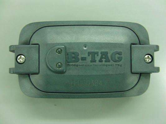
SBDB812A
Sep 16, 2014Tire Pressure Monitoring System
Equipment Class
DSC - Part 15 Security/Remote Control Transmitter
SBD11S-US
Feb 20, 201411S-US
Equipment Class
DSC - Part 15 Security/Remote Control Transmitter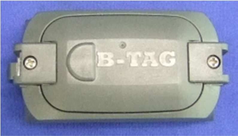
SBDB812
Jun 18, 2012Tire Pressure Monitoring System
Equipment Class
DSR - Part 15 Remote Control/Security Device Transceiver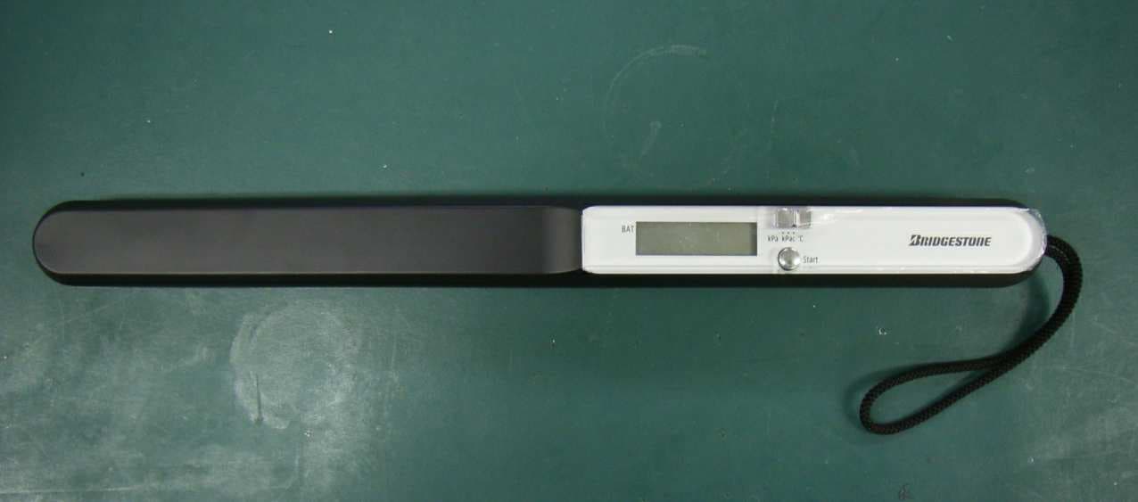
SBDK111
Dec 05, 2006TPMS Hand Reader
Equipment Class
DCD - Part 15 Low Power Transmitter Below 1705 kHz