SBDB812ATire Pressure Monitoring System
Bridgestone Corporation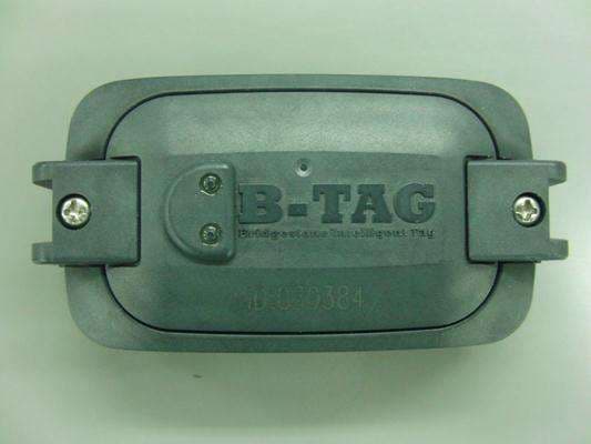
Click to zoom
Application Details
- Equipment Class
- DSC - Part 15 Security/Remote Control Transmitter
- Date of Grant
- Sep 16, 2014
- Application Purpose
- Original Equipment
- Date of Application
- Sep 16, 2014
- Equipment Note
- Tire Pressure Monitoring System
- Frequency Range
- 433.92000000 - 433.92000000
- Company
- Bridgestone Corporation
- Country
- Japan
Documents & Files
Document Text
Text extracted from the exhibit documents filed with the FCC. Open a document above to read the original.
Users Manual
B-TAG Bridgestone Intelligent Tag MODEL B812 User’s Manual System organization About B-TAG The B-TAG (Bridgestone Intelligent TAG system (below, it calls “the system” or “this system”), with the sensor which is installed inside the tire, measures the tire pressure and temperature. - The organization and the function - This system consists of the sensor, the receiver the ECU, the indicator, the hand-held reader and the tag reader, uses with the kind of configuration which is shown in the figure. This system has the following function. ・The tire pressure and temperature, indicating warning for them and the system state in the Hand-held reader. The wireless is communicated with ECU set up in the vehicle with the Hand-held reader, worth of one vehicle the tire pressure and temperature are read to, and it is possible to display it. ・The warning, the error code, the tire pressure and temperature indicating in the indicator. If the tire pressure and temperature which was measured with the sensor inside the tire have come off from the set range, it puts out warning to the indicator where is set in the driver's seat and informs the operator. In addition, when the ECU detects the breakdown of the system, the error code which displays the contents of breakdown is indicated in the indicator. Furthermore, the tire pressure and temperature can be indicated in the indicator with the indicator’s button operation. ・Measurement of the tire pressure and the temperature that uses the Tag reader. With the Tag reader, the tire pressure and temperature can read directly from the sensor inside the tire. And it can be indicated read data in the Hand-held reader by the wireless communication. In this system, for the tire pressure management, it is necessary to set below. ・Set up of the ECU By the Hand-held reader, the ECU can set up and change the information of model, the vehicle number etc and the warning condition. ・Set up of the Sensor By using the Hand-held reader and the Tag reader, it can set up and change the installation of the vehicle classification, the number and the information of the tire position to the Sensor. Ƃ ・Switch of operation mode of the Sensor By using the Hand-held reader and the Tag reader, it can switch the “The mode of Normal sending”, “The mode of sending stop” and “The mode of filling up the tire internal pressure”. ・Set up of the Tag reader By the Hand-held reader, it can set up and change the number of the Tag reader and information of the monthly average temperature etc to the Tag reader. This EUT has two following modes. ・Normal mode System doesn't detect any emergency signal. ・Alarm mode System detects that the pressure of the tire is too low and/or temperature is too high. Notices for using in UAS / Canada This device complies with Part 15 of FCC Rules and Industry Canada licence-exempt RSS standard(s). Operation is subject to the following two conditions: (1) this device may not cause interference, and (2) this device must accept any interference, including interference that may cause undesired operation of this device. Le présent appareil est conforme aux la partie 15 des règles de la FCC et CNR d'Industrie Canada applicables aux appareils radio exempts de licence. L'exploitation est autorisée aux deux conditions suivantes : (1) l'appareil ne doit pas produire de brouillage, et (2) l'utilisateur de l'appareil doit accepter tout brouillage radioélectrique subi, même si le brouillage est susceptible d'en compromettre le fonctionnement. This equipment has been tested and found to comply with the limits for a Class B digital device, pursuant to Part 15 of the FCC Rules. These limits are designed to provide reasonable protection against harmful interference in a residential installation. This equipment generates use and can radiate radio communications. However, there is no guarantee that interference will not occur in a particular installation. If this equipment does cause harmful interference to radio or television reception, which can be determined by turning the equipment off and on, the user is encouraged to correct the interference by one or more of the following measures: - Reorient or relocate the receiving antenna. - Increase the separation between the equipment and receiver. - Connect the equipment into an outlet on a circuit different from that to which the receiver is connected. - Consult the dealer or an experienced radio/TV technician for help. This transmitter must not be co-located or operated in conjunction with any other antenna or transmitter. This equipment complies with FCC/IC radiation exposure limits set forth for an uncontrolled environment and meets the FCC radio frequency (RF) Exposure Guidelines and RSS-102 of the IC radio frequency (RF) Exposure rules. This equipment has very low levels of RF energy that it deemed to comply without maximum permissive exposure evaluation (MPE). [※But it is desirable that it should be installed and operated keeping the radiator at least 20cm or more away from person's body.] Cet équipement est conforme aux limites d’exposition aux rayonnements énoncées pour un environnement non contrôlé et respecte les règles les radioélectriques (RF) de la FCC lignes directrices d'exposition et d’exposition aux fréquences radioélectriques (RF) CNR-102 de l’IC. Cet équipement émet une énergie RF très faible qui est considérée conforme sans évaluation de l’exposition maximale autorisée. [※Cependant, il est souhaitable qu'il devrait être installé et utilisé en gardant une distance de 20 cm ou plus entre le dispositif rayonnant et le corps.]
External Photos
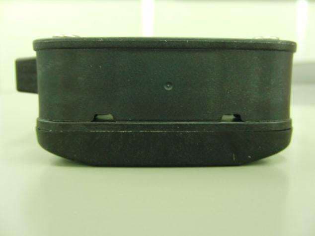
SENSOR B812 External Photograph TOP View BOTTOM View (1/2) (2/2) SIDE View BACK Side View
ID Label/Location Info
BRIDGESTONE CORPORATION MODEL:B812 FCCID:SBDB812A IC:5381A-B812 Laser Marking 50 7 B812 Label Location
Internal Photos
SENSOR B812 Internal Photograph (1/1) TOP View BOTTOM View
Test Report
Test report No. : 10261272H-A-R3 Page : 2 of 17 Issued date : April 14, 2014 Revised date : September 17, 2014 FCC ID : SBDB812A UL Japan, Inc. Ise EMC Lab. 4383-326 Asama-cho, Ise-shi, Mie-ken 516-0021 JAPAN Telephone : +81 596 24 8999 Facsimile : +81 596 24 8124 REVISION HISTORY Original Test Report No.: 10261272H-A Revision Test report No. Date Page revised Contents - (Original) 10261272H-A April 14, 2014 - - 1 10261272H-A-R1 June 19, 2014 P.5 Correction of Clause 3.2 1 10261272H-A-R1 June 19, 2014 P.8 Correction of Clause 4.1 1 10261272H-A-R1 June 19, 2014 P.11 Correction of Calculation of “Total transmission times per hour”. 1 10261272H-A-R1 June 19, 2014 P.18, 19 Correction of APPENDIX 4 2 10261272H-A-R2 September 10, 2014 P.5 Correction of Procedures table in Clause 3.2. 2 10261272H-A-R2 September 10, 2014 P.11 Correction of Automatically deactivate data. 2 10261272H-A-R2 September 10, 2014 P.15 Addition of test instruments. 2 10261272H-A-R2 September 10, 2014 P.18, 19 Correction of APPENDIX 4. 3 10261272H-A-R3 September 17, 2014 - (previous report P.18,19) Deletion of APPENDIX 4. Test report No. : 10261272H-A-R3 Page : 3 of 17 Issued date : April 14, 2014 Revised date : September 17, 2014 FCC ID : SBDB812A UL Japan, Inc. Ise EMC Lab. 4383-326 Asama-cho, Ise-shi, Mie-ken 516-0021 JAPAN Telephone : +81 596 24 8999 Facsimile : +81 596 24 8124 CONTENTS PAGE SECTION 1: Customer information ·············································································· 4 SECTION 2: Equipment under test (E.U.T.) ···································································· 4 SECTION 3: Test specification, procedures & results························································· 5 SECTION 4: Operation of E.U.T. during testing ······························································· 8 SECTION 5: Radiated emission (Electric Field Strength of Fundamental and Spurious Emission) 9 SECTION 6: Automatically deactivate ········································································· 10 SECTION 7: -20dB and 99% Occupied Bandwidth ························································· 10 APPENDIX 1: Data of EMI test ·················································································· 11 Automatically deactivate................................................................................................................... 11 Radiated Emission (Electric Field Strength of Fundamental and Spurious Emission) ..................... 12 -20dB Bandwidth .............................................................................................................................. 13 Duty Cycle ........................................................................................................................................ 14 APPENDIX 2: Test Instruments ················································································· 15 APPENDIX 3: Photographs of test setup ······································································· 16 Radiated emission ............................................................................................................................. 16 Worst case position ........................................................................................................................... 17 Test report No. : 10261272H-A-R3 Page : 4 of 17 Issued date : April 14, 2014 Revised date : September 17, 2014 FCC ID : SBDB812A UL Japan, Inc. Ise EMC Lab. 4383-326 Asama-cho, Ise-shi, Mie-ken 516-0021 JAPAN Telephone : +81 596 24 8999 Facsimile : +81 596 24 8124 SECTION 1: Customer information Company Name : Bridgestone Corporation Address : 3-1-1, Ogawahigashi-cho, Kodaira-shi, Tokyo, 187-8531, Japan Telephone Number : +81-42-342-6326 Facsimile Number : +81-42-345-6244 Contact Person : Toshihiro Miyazaki SECTION 2: Equipment under test (E.U.T.) 2.1 Identification of E.U.T. Type of Equipment : Tire Pressure Monitoring System Model No. : B812(Sensor) Serial No. : Refer to Clause 4.2 Rating : DC 3.0V Receipt Date of Sample : March 26, 2014 Country of Mass-production : Japan Condition of EUT : Engineering prototype (Not for Sale: This sample is equivalent to mass-produced items.) Modification of EUT : No Modification by the test lab 2.2 Product Description Model No: B812 (referred to as the EUT in this report) is the Tire Pressure Monitoring System. General Specification Clock frequency(ies) in the system : 2MHz (microcomputer) Radio Specification Transmitter part Radio Type : Transmitter Frequency of Operation : 433.92MHz Modulation : FSK Power Supply (radio part input) : DC 3.0V Antenna type : Loop Antenna Antenna Gain : -15dBi Receiver part Type of Receiver : Receiver Frequency of operation : 125kHz Modulation : CMI Antenna type : Coil Antenna Test report No. : 10261272H-A-R3 Page : 5 of 17 Issued date : April 14, 2014 Revised date : September 17, 2014 FCC ID : SBDB812A UL Japan, Inc. Ise EMC Lab. 4383-326 Asama-cho, Ise-shi, Mie-ken 516-0021 JAPAN Telephone : +81 596 24 8999 Facsimile : +81 596 24 8124 SECTION 3: Test specification, procedures & results 3.1 Test Specification Test Specification : FCC Part 15 Subpart C: 2014, final revised on May 1, 2014 and effective June 2, 2014 Title : FCC 47CFR Part15 Radio Frequency Device Subpart C Intentional Radiators Section 15.231 Periodic operation in the band 40.66 - 40.70MHz and above 70MHz * The revision on May 1, 2014 does not affect the test specification applied to the EUT. 3.2 Procedures and results Item Test Procedure Specification Worst margin Results Remarks Conducted emission FCC: ANSI C63.4:2003 7. AC powerline conducted emission measurements FCC: Section 15.207 N/A N/A *1) - IC: RSS-Gen 7.2.4 IC: RSS-Gen 7.2.4 Automatically Deactivate FCC: ANSI C63.4:2003 13. Measurement of intentional radiators FCC: Section 15.231(e) N/A Complied Radiated IC: - IC: RSS-210 A1.1.5 Electric Field Strength of Fundamental Emission FCC: ANSI C63.4:2003 13. Measurement of intentional radia…
Text truncated - open the document above for the full version.
Test Setup Photos
Test report No. : 10261272H-A-R3 Page : 16 of 17 Issued date : April 14, 2014 Revised date : September 17, 2014 FCC ID : SBDB812A UL Japan, Inc. Ise EMC Lab. 4383-326 Asama-cho, Ise-shi, Mie-ken 516-0021 JAPAN Telephone : +81 596 24 8999 Facsimile : +81 596 24 8124 APPENDIX 3: Photographs of test setup Radiated emission Photo 1 Photo 2 Test report No. : 10261272H-A-R3 Page : 17 of 17 Issued date : April 14, 2014 Revised date : September 17, 2014 FCC ID : SBDB812A UL Japan, Inc. Ise EMC Lab. 4383-326 Asama-cho, Ise-shi, Mie-ken 516-0021 JAPAN Telephone : +81 596 24 8999 Facsimile : +81 596 24 8124 Worst case position (Horizontal: X-axis/Vertical : Y-axis) X-axis Y-axis Z-axis End of Report
Contact Information
Applicant
Naoya Hamahata(Manager)
Technical Contact
UL Japan, Inc.Motoya Imura
[email protected]81-596-24-8999
4383-326 Asama-cho, Ise-shi · Mie-ken · Japan
Test Firm
UL Japan, Inc. Head office EMC Lab.Tetsuya Hashimoto
Technical Specifications
| # | Rule Parts | Frequency Range | Power Output |
|---|---|---|---|
| 1 | 15.231(e) | 433.92 MHz - 433.92 MHz | - |
Other Applications from Bridgestone Corporation
SBDK712
May 27, 2015Tag Reader
Equipment Class
DCD - Part 15 Low Power Transmitter Below 1705 kHz
SBD11S-US
Feb 20, 201411S-US
Equipment Class
DSC - Part 15 Security/Remote Control Transmitter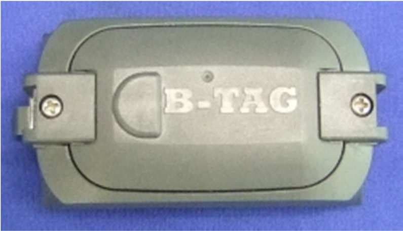
SBDB812
Jun 18, 2012Tire Pressure Monitoring System
Equipment Class
DSR - Part 15 Remote Control/Security Device Transceiver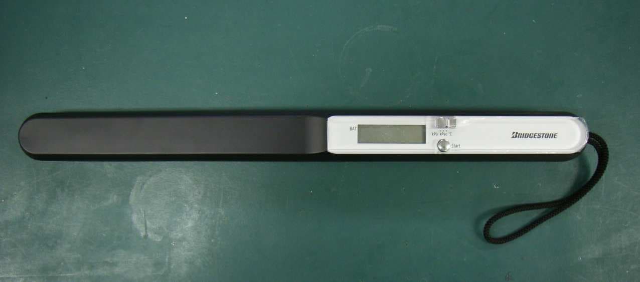
SBDK111
Dec 05, 2006TPMS Hand Reader
Equipment Class
DCD - Part 15 Low Power Transmitter Below 1705 kHz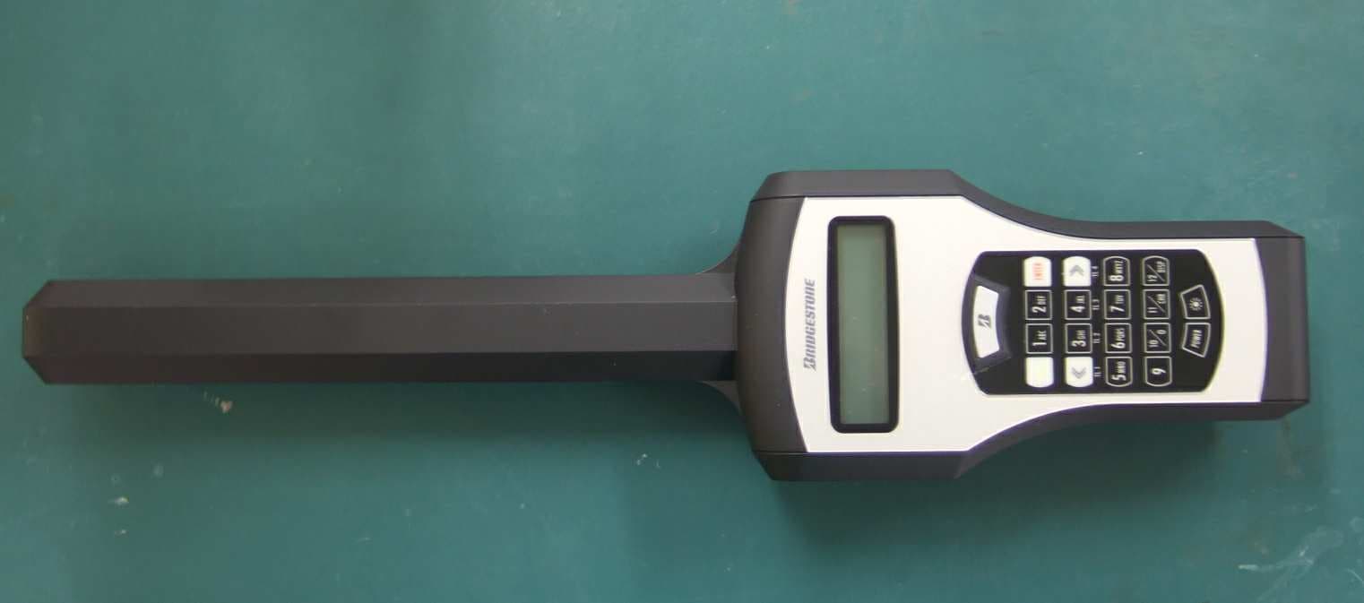
SBDH211
Aug 30, 2006TPMS Hand Reader
Equipment Class
DXT - Part 15 Low Power Transceiver, Rx Verified