SBDH211TPMS Hand Reader
Bridgestone Corporation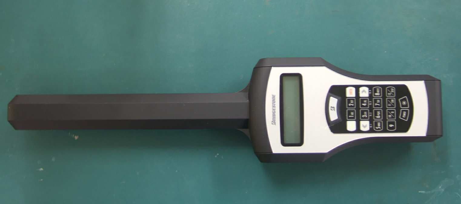
Click to zoom
Application Details
- Equipment Class
- DXT - Part 15 Low Power Transceiver, Rx Verified
- Date of Grant
- Aug 30, 2006
- Application Purpose
- Original Equipment
- Date of Application
- Aug 29, 2006
- Equipment Note
- TPMS Hand Reader
- Frequency Range
- 0.12500000 - 0.12500000
- Company
- Bridgestone Corporation
- Country
- Japan
Documents & Files
Document Text
Text extracted from the exhibit documents filed with the FCC. Open a document above to read the original.
Users Manual
Tire-Pressure Monitoring System For truck and bus For use only in Europe (model:H212) or U.S.A. (model:H211) Apr. 2006 Base REG Developmen t 2006.04 Base Copyright © 2006 Bridgestone Corporation Manufacturing and Sales Bridgestone Corporation 1-10-1 Kyobashi Chuoku Tokyo 104-8340 http://www.bridgestone.co.jp/ Hand Reader Operation Guide Notice to user What is a Tire-Pressure Monitoring System? Tire-pressure monitoring system is an advanced system that measures the tire pressure and temperature with sensors mounted inside the tire and enables vehicle management using the measured data. This product is designed exclusively for trucks and buses. This product has two design for use within Europe and USA. It cannot be used other country due to difference in radio wave regulations. Attention for product model number. For Europe......model H212 For USA.......... model H211 Be sure to read and understand the content of the operation guide before installing or removing. Keep this guide in a safe place and refer to it as necessary. 1 SAFETY PRECAUTIONS PART NAMES & FUNCTIONS BASIC OPERATION MES mode REG mode VIEWING SAVED DATA TRANSFERRING SAVED DATA APPENDIX TROUBLESHOOTING SERVICE & REPAIR INDEX INTRODUCTION Introduction This guide describes how to use the hand reader for tire-pressure monitoring system (referred hereafter as "this product" or "hand reader"). Please read and understand the content before using. About This Product This product can collect tire pressure and internal temperature data from the tire-pressure monitoring system sensors mounted inside the tire (rim) and save them in its memory. Tire pressure and internal temperature are measured by bringing the antenna of the hand reader near the valve of the tire and receiving the radio wave. In addition, the following functions are available using the keys. Store view received data You can store and view pressure and temperature data for up to 90 vehicles (1080 tires or 90 vehicles x 12 per vehicle for 12 wheeler). Refer to section "4-1 Saving and controlling measured data" (page 19) for the content of the saved data. Transfer saved data to PC You can use the included Data Transfer Tool to transfer the data saved in the hand reader to a PC in Microsoft Excel readable format (CSV). You can use the data with many applications once it is transferred. REG information by tire position You can register and REG pressure and temperature data by tire position. You can transfer the registered data to PC for use with other applications. Package Content Check that the following items are included in the package. Hand reader x 1Connection cable x 1 Battery (AAA) x 4 Data Transfer Tool CD-ROM x 1 Operation Guide x 1 Depth gauge Tire-Pressure Monitoring System For truck and bus For use only in Europe (model:H212) or U.S.A. (model:H211) Hand Reader Operation Guide Notice to user What is a Tire-Pressure Monitoring System? Tire-pressure monitoring system is an advanced system that measures the tire pressure and temperature with sensors mounted inside the tire and enables vehicle management using the measured data. This product is designed exclusively for trucks and buses. This product has two design for use within Europe and USA. It cannot be used other country due to difference in radio wave regulations. Attention for product model number. For Europe...... model H212 For USA.......... model H211 Be sure to read and understand the content of the operation guide before installing or removing. Keep this guide in a safe place and refer to it as necessary. Items included in the hand reader packageOptionally purchased items Option 2 About Tire-Pressure Monitoring System The tire-pressure monitoring system (hereafter referred to as "system" or "this system") is a system that monitors the tire pressure and temperature using sensors mounted inside tires (rim). This system is available as "Hand Reader Type" and "On-Board Type". Purchase the product that is appropriate for your intended use. Hand reader type This system receives the radio wave from the sensor with a portable hand reader. The radio wave from the sensor is received with the vehicle stopped. It cannot be used when moving. <Equipment Configuration> On-board type This system measure and monitors the radio wave from the sensor with a display and warning lamp mounted on the dashboard. When there is a tire problem, the display and warning lamps on the dashboard emit alarms to notify the driver. The tire status can be monitored while moving. <Equipment Configuration> Sensor Hand reader Receiver Sensor Example of installing 4 receivers and 10 sensors Receiver Cable Vehicle power supply ▪BAT ▪IGN ▪GND ECU Display Warning lamp Warning lamp Display ECU Receiver Sensor Install on dashboard Install inside cabi n Install on vehicle or fram e Install inside tire (rim ) 3 SAFETY PRECAUTIONS PART NAMES & FUNCTIONS BASIC OPERATION MES mode REG mode VIEWING SAVED DATA TRANSFERRING SAVED DATA APPENDIX TROUBLESHOOTING SERVICE & REPAIR INDEX INTRODUCTION Operation Guide Combination The following two operation guides are necessary to use the Hand Reader type of Tire-Pressure Monitoring System. Read the guide appropriate for your system. GuideContent Tire-Pressure Monitoring System Hand Reader Operation Guide (this guide) Describes the hand reader operation method and precautions Tire-Pressure Monitoring System Sensor Operation Guide Describes sensor installation, rim installation and removal, and precautions • Unauthorized duplication or reprint of any part of this operation guide or in its entirety is prohibited. • If this operation manual becomes smudged and unreadable, obtain a new one from your dealer. • Contact your dealer if there is any misprint or missing page and for questions about its content. • Microsoft and Excel are registered trademarks of Microsoft Corporation in the U.S. and other countries. • Other system and product names are registered trademark or trademark of the respective company. The t…
Text truncated - open the document above for the full version.
Users Manual
16 Relationship between tire position and number keys Truck (including tractor), bus Tires: 4Tires: 6Tires: 8, Axle arrangement: 2 • 2-D Tires: 8, Axle arrangement: 2-D • 2Tires: 10Tires: 12 Trailer Look at the [TL1] etc. displayed at the bottom of the key when entering trailer tire position. Tires: 2, Axle arrangement: 1 axlesTires: 4, Axle arrangement: 1 axlesTires: 4, Axle arrangement: 2 axles Tires: 6, Axle arrangement: 3 axlesTires: 8, Axle arrangement: 2 axlesTires: 12, Axle arrangement: 3 axles 17 SAFETY PRECAUTIONS INTRODUCTION PART NAMES & FUNCTIONS MES mode REG mode VIEWING SAVED DATA TRANSFERRING SAVED DATA APPENDIX TROUBLESHOOTING SERVICE & REPAIR INDEX BASIC OPERATION 2-8Reading data from sensor This section describes how to read the data from the sensor mounted on the tire. 1. Press the POWER switch to turn on the power. See section "2-1 Power ON" (page 10). 2. Select the measurement mode and set. See "3 Performing measurement only" (page 17) and "4 Saving the measured data" (page 19). 3. Gently touch the tip of the antenna against the sidewall near the valve of the tire to be measured. 4. Press the B button. • The data will be measured when the B button is released. • Measurement will be performed only once when you release the B button even if you continue pressing it. 5. The data is received from the sensor inside the tire. You want to measure the inside tire of double tire Insert the antenna from the ornamental hole of the outer tire wheel and gently touch against the sidewall near the valve. 2-9Viewing the measured data The measured data appears on the LCD panel as follows. When you measure in REG mode VN=EF5253 TP=01 1000kPa 45d@091 4 Vehicle no.Tire position Measured pressured Measured temperature Compensated pressure Measured pressured : Shows the measured tire pressure. Measured temperature : Shows the measured tire internal temperature. Compensated pressure : Shows the measured tire pressure compensated to the pressure when the tire internal temperature is 20°C. See section "7-2 Compensated pressure calculation" (page 35) for details. • The tire pressure changes with tire internal temperature. Therefore, if it is measured after driving, the tire will be warm and the pressure will be higher than before driving when the tire is cool. If you want to REG the tire pressure without the effect of the tire internal temperature, use the temperature converted to the pressure (called compensated pressure) at the reference temperature (20°C). Press MES ID=123ABC 1000kPa 45d@091 4 Sensor ID When you measure in MES mode When Measured pressured Measured temperature Compensated pressure When 18 Performing Measurement Only (MES mode) To perform measurement only, select MES mode from the Select Menu screen. 1. Press the POWER switch to turn on the power. See section "2-1 Power ON" (page 10) 2. Press the [2] key and select "2MES" when the Select Menu screen appears. See section "2-4 Selecting operation mode" (page 11) 3. MES Mode Input Wait screen appears on the LCD panel. 4. Gently touch the tip of the antenna against the sidewall near the valve of the tire to be measured. • Note that if you touch the tip of the antenna against the rim or other metal parts, radio wave from the sensor will be blocked and you will not be able to receive the data. MES MODE READY MES Mode Input Wait screen You want to measure the inside tire of double tire Insert the antenna from the hole in the outer rim and gently touch the tip of the antenna against the sidewall near the valve. If the rim is installed properly, the valve of the outer tire should be at the opposite position from the valve of the inner tire. When SELECT MENU 1REG 2MES 3OB Select Menu screen ` Press Press 19 SAFETY PRECAUTIONS INTRODUCTION PART NAMES & FUNCTIONS BASIC OPERATION REG mode VIEWING SAVED DATA TRANSFERRING SAVED DATA APPENDIX TROUBLESHOOTING SERVICE & REPAIR INDEX MES mode 5. Press the B button . • The data will be measured when the B button is released. • Measurement will be performed only once when you release the B button even if you continue pressing it. 6. Data is received from the sensor inside the tire. 7. If the data is received normally, an alarm (0.5 sec) sounds twice and the received data appears on the LCD panel. 8. To continue measuring another tire or repeat measurement of the same tire, repeat steps 4 and 5 . A long alarm (1.5 sec) sounds once When there is no response from the sensor after pressing the B button or the data could not be received correctly, the Receive Error screen appears and then the B button Input Wait screen appears. At this point, be careful of the following and press the B button once more to repeat measurement. • Keep the tip of the antenna away from rim and other metal parts. • Bring the tip of the antenna closer to the valve. • Stand the tip of the antenna against the sidewall as perpendicular as possible (see figure below). • Press the B button and make sure the tip of the antenna is as described above when releasing the button. • Check the presence of valve mark and the check sheet to determine that the tire is the one with sensor installed. If you still cannot receive data, see "8 Troubleshooting" (page 39). The screen returns to Select Menu screen if you press the [BACK] key while the Receive Error screen is displayed. When Receive Error screen MES RCV FAIL! RETRY When data is received successfully Press MES ID=123ABC 1000kPa 45d@091 4 Sensor ID Measured pressured Measured temperature Compensated pressure 20 Saving the Measured Data (REG mode) Select REG mode from the Select Menu screen to measure while saving the measured data to the hand reader. In this mode, you must enter or select vehicle information such as date, customer no., vehicle no., vehicle type, number of tires, and Axle arrangement before measurement. 4-1Saving and controlling measured data The data measured in REG mode can be saved and controlled as follows. • Save and control in hand reader memory Pres…
Text truncated - open the document above for the full version.
Users Manual
Tire-Pressure Monitoring System For truck and bus For use only in Europe (model:H212) or U.S.A. (model:H211) Apr. 2006 Base REG Developmen t 2006.04 Base Copyright © 2006 Bridgestone Corporation Manufacturing and Sales Bridgestone Corporation 1-10-1 Kyobashi Chuoku Tokyo 104-8340 http://www.bridgestone.co.jp/ Hand Reader Operation Guide Notice to user What is a Tire-Pressure Monitoring System? Tire-pressure monitoring system is an advanced system that measures the tire pressure and temperature with sensors mounted inside the tire and enables vehicle management using the measured data. This product is designed exclusively for trucks and buses. This product has two design for use within Europe and USA. It cannot be used other country due to difference in radio wave regulations. Attention for product model number. For Europe......model H212 For USA.......... model H211 Be sure to read and understand the content of the operation guide before installing or removing. Keep this guide in a safe place and refer to it as necessary. 31 SAFETY PRECAUTIONS INTRODUCTION PART NAMES & FUNCTIONS BASIC OPERATION MES mode TRANSFERRING SAVED DATA APPENDIX TROUBLESHOOTING SERVICE & REPAIR INDEX REG mode VIEWING SAVED DATA Viewing Saved Data You can view measurement data (vehicle no. and pressure, temperature, and sensor ID at the specified tire position) saved in the hand reader for up to 90 vehicles (1080 tires or 90 vehicles x 12 per vehicle for 12 wheeler). • The data can be viewed in REG mode. It can be viewed from any screen in REG mode. 1. Select REG mode. See section "2-4 Selecting operation mode" (page 11) 2. Press the [DISP] key for at least 2 seconds. 3. An alarm (0.5 sec) sounds once and the Saved Data Display screen appears. 4. Press the [«] or [»] key. 5. The memory sequence no. changes. Memory sequence no. is assigned to the saved data in sequence. Therefore, you can view all saved data regardless of the vehicle no. Press at least 2 seconds. Press either key to view saved data. You want to view by vehicle 1. Press the [BACK] or [ENTER] key and select the vehicle no. of the vehicle to view the saved data. • To select the vehicle registered prior to the displayed vehicle no. ... [BACK] Key • To select the vehicle registered after the displayed vehicle no. ... [ENTER] key 2. With the vehicle no. of the desired vehicle displayed, press the [«] or [»] key. 3. Saved data for the selected vehicle are displayed in order. 4. If you continue pressing the [«] or [»] key, the vehicle no. changes and the saved data for the next or previous vehicle is displayed. You want to quit viewing 1. Press the [DISP] key for at least 2 seconds. 2. An alarm (0.5 sec) sounds once and the REG Mode screen appears. When Press either key to view saved data. Press either key and select vehicle no. 1079 EF5253PO=10 1000k 45d ABC001 Memory sequence no. Vehicle no. Tire position Measured pressured Measured temperature Sensor ID 32 VIEWING SAVED DATA TRANSFERRING SAVED DATA Transferring Saved Data to PC You can transfer the measurement data saved in hand reader memory to PC to store and REG data on your PC. 6-1Installing the software Copy the Data Transfer Tool in the included CD-ROM to your PC. Have the icon displayed on the desktop after copying. 6-2Transferring Data to PC 1. Connect the PC and hand reader using the included connection cable connected to the hand reader connector and PC serial connector. • Check the operation manual of your PC for the location of the serial connector. N O T E • Check that the power of the hand reader and PC are off before connecting them. The hand reader or PC may be damaged if the power is not turned off before connecting. 2. Press the POWER switch of the hand reader to turn on the power. 3. Turn ON the PC power. 4. Double click the icon on your PC desktop and start the Data Transfer Tool. 5. The Specify Communication Port screen appears. 6. Click the pull down button by the Com Port No field to display the [Com Port No] dropdown list and select the serial port no. (COM1 to COM8) to which you connected the cable. • If you are using a desktop PC, the serial port no. is normally COM1 or COM2. 7. Click the [Enter] button on the Communication Port Setup screen. Communication Port Setup screen 33 SAFETY PRECAUTIONS INTRODUCTION PART NAMES & FUNCTIONS BASIC OPERATION MES mode REG mode VIEWING SAVED DATA APPENDIX TROUBLESHOOTING SERVICE & REPAIR INDEX VIEWING SAVED DATA TRANSFERRING SAVED DATATRANSFERRING SAVED DATA 12. Check that the Select Menu screen appears on the hand reader. 13. Press the [BACK] key of the hand reader for 2 seconds. 14. The following screens appear on the hand reader and PC and data transfer starts. Hand Reader PC N O T E • The power does not go off while sending data to PC. DATA SENDING IN PROGRESS! Transferring Data screen (Flashes) Receiving Data screen 8. The Save As screen appears. 9. In the Save As screen, specify the location to save the transferred data and enter a file name in the file name field. • If you do not enter the file name, the file name will be "(Transferred) date. time.csv" (Example: 20060523164020.csv). Change this file name as necessary. 10. Click the [Save] button. 11. The Data Waiting screen appears and the PC waits for data from the hand reader. Save As screen Error screen is displayed If you select a non-existing serial port, the following Error screen appears. Error screen 1. Click the [OK] button to close the Error screen. 2. Check the serial port no. and retry. When You want to cancel save Click the [Cancel] button to cancel saving when the Specify Save File screen is displayed. When Data Waiting screen You want to cancel save Click the [Cancel] button to cancel saving when the Data Input Wait screen is displayed. If you click the [Cancel] button, an empty file is created with the name specified in step 9 . When Press for 2 seconds. SELECT MENU 1REG 2MES 3OB Select Menu screen You want to cancel data transfer Press the [Cancel] button on the Rece…
Text truncated - open the document above for the full version.
External Photos
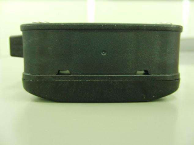
HAND-READER_H211 External photograph TOP View SIDE View BOTTOM View
Internal Photos
1/3 HAND-READER_H211 Internal photograph TOP View of Total TOP View of MAIN PCB BOTTOM View of MAIN PCB 2/3 TOP View of SWITCH PCB BOTTOM View of SWITCH PCB 3/3 TOP View of ANTENNA PCB BOTTOM View of SWITCH PCB
Test Report
Test report No. : 26JE0237-HO-A Page : 1 of 18 Issued date : August 23, 2006 FCC ID : SBDH211 UL Apex Co., Ltd. Head Office EMC Lab. 4383-326 Asama-cho, Ise-shi, Mie-ken 516-0021 JAPAN Telephone : +81 596 24 8116 Facsimile : +81 596 24 8124 MF060b(14.06.06) RADIO TEST REPORT Test Report No.: 26JE0237-HO-A Applicant : BRIDGESTONE Co., Ltd. Type of Equipment : HAND READER Model No. : H211 Test standard : FCC Part 15 Subpart B Class B: 2006 FCC Part 15 Subpart C: 2006 FCC ID : SBDH211 Test Result : Complied 1. This test report shall not be reproduced in full or partial, without the written approval of UL Apex Co., Ltd. 2. The results in this report apply only to the sample tested. 3. This equipment is in compliance with above regulation. 4. The test results in this report are traceable to the national or international standards. Date of test: _________________________________ Tested by: _________________________________ Yasuyuki Fukui EMC Services Approved by : _________________________________ Naoki Sakamoto Group Leader of EMC Services NVLAP LAB CODE: 200572-0 This laboratory is accredited by the NVLAP LAB CODE 200572-0, U.S.A. The tests reported herein have been performed in accordance with its terms of accreditation. *As for the range of Accreditation in NVLAP, you may refer to the WEB address, http://ulapex.jp/emc/nvlap.htm July 11, 2006 Test report No. : 26JE0237-HO-A Page : 2 of 18 Issued date : August 23, 2006 FCC ID : SBDH211 UL Apex Co., Ltd. Head Office EMC Lab. 4383-326 Asama-cho, Ise-shi, Mie-ken 516-0021 JAPAN Telephone : +81 596 24 8116 Facsimile : +81 596 24 8124 MF060b(14.06.06) CONTENTS PAGE SECTION 1: Client information ............................................................................................................ 3 SECTION 2: Equipment under test (E.U.T.)........................................................................................ 3 SECTION 3: Test specification, procedures & results......................................................................... 4 SECTION 4: Operation of E.U.T. during testing .................................................................................8 SECTION 5: Radiated emission (Fundamental and Spurious Emission and –26dB Bandwidth) .... 9 APPENDIX 1: Photographs of test setup ............................................................................................ 10 Radiated Emission............................................................................................................................. 10 Worst Case Position (EUT: X-axis) ................................................................................................. 11 APPENDIX 2: Test instruments .......................................................................................................... 12 APPENDIX 3: Data of EMI test........................................................................................................... 13 Radiated Emission (FCC 15B Receiving)........................................................................................ 13 Radiated Emission below 30MHz (Fundamental and Sprious Emission).................................... 15 Radiated Emission above 30MHz (Sprious Emission) ................................................................... 16 -26dB Bandwidth............................................................................................................................... 17 99% Occupied Bandwidth................................................................................................................ 18 Test report No. : 26JE0237-HO-A Page : 3 of 18 Issued date : August 23, 2006 FCC ID : SBDH211 UL Apex Co., Ltd. Head Office EMC Lab. 4383-326 Asama-cho, Ise-shi, Mie-ken 516-0021 JAPAN Telephone : +81 596 24 8116 Facsimile : +81 596 24 8124 MF060b(14.06.06) SECTION 1: Client information Company Name : BRIDGESTONE Co., Ltd. Address : 3-1-1, Ogawahigashi-Cho, Kodaira-Shi, Tokyo, 187-8531 Japan Telephone Number : +81-42-342-6326 Facsimile Number : +81-42-342-6596 Contact Person : Toshihiro Miyazaki SECTION 2: Equipment under test (E.U.T.) 2.1 Identification of E.U.T. Type of Equipment : HAND READER Model No. : H211 Sample No. : 000013 Country of Manufacture : Japan Rating : DC4.8V, 0.25A Receipt Date of Sample : July 10, 2006 Condition of EUT : Production model Modification of EUT : No modification by the test lab. 2.2 Product Description Model No: H211 (referred to as the EUT in this report) is the HAND READER Clock frequency : CPU Clock: 10MHz CPU Sub Clock: 32.768kHz Transmission Frequency Dividing Clock: 8MHz Receiving Local Clock: 40.7125MHz Equipment type : Transceiver [Transmitter part] Frequency of Operation : 125kHz Type of Modulation : ASK Mode of Operation : Simplex Method of Frequency Generation : Crystal Antenna : Ferrite Bar Antenna [Receiver part] Receiving frequency : 315MHz Intermediate frequency : 10.7MHz Antenna : Loop Antenna Test report No. : 26JE0237-HO-A Page : 4 of 18 Issued date : August 23, 2006 FCC ID : SBDH211 UL Apex Co., Ltd. Head Office EMC Lab. 4383-326 Asama-cho, Ise-shi, Mie-ken 516-0021 JAPAN Telephone : +81 596 24 8116 Facsimile : +81 596 24 8124 MF060b(14.06.06) SECTION 3: Test specification, procedures & results 3.1 Test Specification Test Specification : FCC Part15 Subpart B: 2006 FCC Part15 Subpart C: 2006 Title : FCC 47CFR Part15 Radio Frequency Device Subpart B Unintentional Radiators FCC 47CFR Part15 Radio Frequency Device Subpart C Intentional Radiators Section 15.205 Restricted bands of operation Section 15.209 Radiated emission limits, general requirements FCC 15.31 (e) The test was performed with the New Battery (DC 4.8V) and the constant voltage was supplied to the EUT during the test. Therefore, the EUT complies with the requirement of Section 15.31 (e). FCC 15.111(b) The receiving antenna is mounted inside of the EUT and it is not removable. Therefore, the EUT complies with the requirement of Section 15.111(b). FCC Part 15.203 …
Text truncated - open the document above for the full version.
Test Report
Test report No. : 26JE0237-HO-A Page : 12 of 18 Issued date : August 23, 2006 FCC ID : SBDH211 UL Apex Co., Ltd. Head Office EMC Lab. 4383-326 Asama-cho, Ise-shi, Mie-ken 516-0021 JAPAN Telephone : +81 596 24 8116 Facsimile : +81 596 24 8124 MF060b(14.06.06) APPENDIX 2: Test instruments EMI test equipment Control No. Instrument Manufacturer Model No Test Item Calibration Date * Interval(month) MAEC-03 Anechoic Chamber TDK Semi Anechoic Chamber 3m RE 2006/03/03 * 12 MOS-13 Thermo-Hygrometer Custom CTH-180 RE 2006/01/19 * 24 MSTW-14 EMI measurement program TSJ TEPTO-DV RE MLPA-02 Loop Antenna Rohde & Schwarz HFH2-Z2 RE 2005/12/06 * 12 MBA-03 Biconical Antenna Schwarzbeck BBA9106 RE 2006/01/29 * 12 MLA-03 Logperiodic Antenna Schwarzbeck USLP9143 RE 2006/01/29 * 12 MHA-06 Horn Antenna Schwarzbeck BBHA9120D RE 2006/01/09 * 12 MCC-51 Coaxial cable UL Apex - RE 2006/03/11 * 12 MAT-30 Attenuator(6dB) TME UFA-01 RE 2006/03/11 * 12 MCC-30 coaxial cable ULApex - RE 2006/05/29 * 12 MPA-13 Pre Amplifier SONOA INSTRUMENT 310 RE 2006/03/25 * 12 MCC-56 Microwave Cable Suhner SUCOFLEX104 RE 2006/04/15 * 12 MPA-11 MicroWave System Amplifier Agilent 83017A RE 2006/03/27 * 12 MSA-04 Spectrum Analyzer Agilent E4448A RE 2006/06/02 * 12 TR-07 Test Receiver Rohde & Schwarz ESCS30 RE 2005/09/14 * 12 All equipment is calibrated with traceable calibrations. Each calibration is traceable to the national or international standards. Test Item: RE: Radiated Emission Test report No. : 26JE0237-HO-A Page : 13 of 18 Issued date : August 23, 2006 FCC ID : SBDH211 UL Apex Co., Ltd. Head Office EMC Lab. 4383-326 Asama-cho, Ise-shi, Mie-ken 516-0021 JAPAN Telephone : +81 596 24 8116 Facsimile : +81 596 24 8124 MF060b(14.06.06) APPENDIX 3: Data of EMI test Radiated Emission (FCC 15B Receiving) DATA OF RADIATED EMISSION TEST UL Apex Co., Ltd. Head Office EMC Lab. No.3 Semi Anechoic Chamber Date : 2006/07/11 16:18:12 Applicant : BRIDGESTONE Co.,Ltd.Report No.:26JE0237-HO Kind of EUT: HAND READER Power:DC 4.8V Model No.: H211 Temp./ Humi.:24 deg.C. / 59 % Serial No.: 000013 Operator:Yasuyuki Fukui Mode / Remarks : Receiving (Max:X-axis) LIMIT : FCC Part15 Subpart B Class B(3m)/USA, below1GHz:QP / RSS-210 / RSS-Gen Exce pt for the data below : adequate margin data below the limits. CHART:WITH FACTOR ANT TYPE:-30MHz LOOP,30-300MHz BICONICAL,300MHz-1000MHz LOGPERIODIC,1000MHz- HORN CALCULATION:RESULT = READING + ANT FACTOR + LOSS(CABLE+ATTEN.) - GAIN(AMP) Fre quency[Hz] [dBuV/m]<< QP DATA >> Horizontal Vertical Horizontal Vertical 30M 1G 50M 70M 100M200M300M500M700M 0 10 20 30 40 50 60 70 80 _ Frequency _ Reading _ DET _ Antenna _ Loss& _ Level _ Angle _ Height _ Polar. _ Limit _ Margin _ Comment _ Frequency _ Reading _ DET _ Factor _ Gain _ Level _ Angle _ Height _ Polar. _ Limit _ Margin _ Comment _ [ MHz ] _ [ dBuV ] _ DET _ [ dB / m ] _ [dB] _ [dBuV/m] _ [Deg] _ [cm] _ Polar. _ [dBuV/m] _ [dB] _ Comment _ 49 .145 _ 27 . 4 _ QP _ 10 .8 _ -24.9 _ 13.3 _ 80 _ 340 _ Hori. _ 40.0 _ 26.7 _ 49 .148 _ 35 . 4 _ QP _ 10 .8 _ -24.9 _ 21.3 _ 1 _ 330 _ Vert. _ 40.0 _ 18.7 _ 52 .380 _ 23 . 5 _ QP _ 10 .0 _ -24.8 _ 8.7 _ 240 _ 389 _ Hori. _ 40.0 _ 31.3 _ 52 .384 _ 33 . 1 _ QP _ 10 .0 _ -24.8 _ 18.3 _ 1 _ 315 _ Vert. _ 40.0 _ 21.7 _ 104.720 _ 34 . 6 _ QP _ 11 .6 _ -23.9 _ 22.3 _ 359 _ 226 _ Vert. _ 43.5 _ 21.2 _ 104.721 _ 26 . 0 _ QP _ 11 .6 _ -23.9 _ 13.7 _ 1 _ 100 _ Hori. _ 43.5 _ 29.8 _ 301.878 _ 28 . 2 _ QP _ 14 .5 _ -22.3 _ 20.4 _ 82 _ 100 _ Hori. _ 46.0 _ 25.6 _ 301.880 _ 22 . 6 _ QP _ 14 .5 _ -22.3 _ 14.8 _ 1 _ 100 _ Vert. _ 46.0 _ 31.2 _ 311.941 _ 28 . 7 _ QP _ 14 .9 _ -22.2 _ 21.4 _ 82 _ 100 _ Hori. _ 46.0 _ 24.6 _ 311.948 _ 22 . 3 _ QP _ 14 .9 _ -22.2 _ 15.0 _ 1 _ 100 _ Vert. _ 46.0 _ 31.0 _ 322.000 _ 28 . 7 _ QP _ 15 .3 _ -22.2 _ 21.8 _ 96 _ 100 _ Hori. _ 46.0 _ 24.2 _ 322.008 _ 22 . 4 _ QP _ 15 .3 _ -22.2 _ 15.5 _ 352 _ 100 _ Vert. _ 46.0 _ 30.5 Test report No. : 26JE0237-HO-A Page : 14 of 18 Issued date : August 23, 2006 FCC ID : SBDH211 UL Apex Co., Ltd. Head Office EMC Lab. 4383-326 Asama-cho, Ise-shi, Mie-ken 516-0021 JAPAN Telephone : +81 596 24 8116 Facsimile : +81 596 24 8124 MF060b(14.06.06) Radiated Emission (FCC 15B Receiving) DATA OF RADIATED EMISSION TEST UL Apex Co., Ltd. Head Office EMC Lab. No.3 Semi Anechoic Chamber Date : 2006/07/11 17:30:22 Applicant : BRIDGESTONE Co.,Ltd.Report No.:26JE0237-HO Kind of EUT : HAND READER Power:DC 4.8V Model No. : H211 Temp./ Humi.:24 deg.C. / 59 % Serial No. : 000013 Operator:Yasuyuki Fukui Mode / Remarks: Receiving (Max:X-axis) LIMIT : FCC Part15 Subpart B Class B(3m)/USA, above1GHz:PK / RSS-210 / RSS-Gen FCC Part15 Subpart B Class B(3m)/USA, above1GHz:AV / RSS-210 / RSS-Gen CHART:WITH FACTOR ANT TYPE:-30MHz LOOP,30-300MHz BICONICAL,300MHz-1000MHz LOGPERIODIC,1000MHz- HORN CALCULATION:RESULT = READING + ANT FACTOR + LOSS(CABLE+ATTEN.) - GAIN(AMP) Frequency[Hz] [dBuV/m] << AV/PEAK DATA >> Horizontal Vertical Horizontal Vertical 1G 2G 0 10 20 30 40 50 60 70 80 90 _ Frequency _ Reading _ DET _ Antenna _ Loss& _ Level _ Angle _ Height _ Polar. _ Limit _ Margin _ Comment _ Frequency _ Reading _ DET _ Factor _ Gain _ Level _ Angle _ Height _ Polar. _ Limit _ Margin _ Comment _ [ MHz ] _ [dBuV ] _ DET _ [ dB / m ] _ [dB] _ [dBuV/m] _ [Deg] _ [cm] _ Polar. _ [dBuV/m] _ [dB] _ Comment _ 1575 . 000 _ 44 . 0 _ PK _ 25 . 3 _ -31.9 _ 37.4 _ 0 _ 100 _ Vert. _ 73.9 _ 36.5 _ 1575 . 000 _ 43 . 6 _ PK _ 25 . 3 _ -31.9 _ 37.0 _ 0 _ 100 _ Hori. _ 73.9 _ 36.9 _ 1575 . 000 _ 30 . 3 _ AV _ 25 . 3 _ -31.9 _ 23.7 _ 0 _ 100 _ Vert. _ 53.9 _ 30.2 _ 1575 . 000 _ 30 . 3 _ AV _ 25 . 3 _ -31.9 _ 23.7 _ 0 _ 100 _ Hori. _ 53.9 _ 30.2 Test report No. : 26JE0237-HO-A Page : 15 of 18 Issued date : August 23, 2006 FCC ID : SBDH211 UL Apex Co., L…
Text truncated - open the document above for the full version.
Contact Information
Applicant
Naoya Hamahata(Manager)
Technical Contact
Test Firm
UL Japan, IncMitsuru Fujimura
Technical Specifications
| # | Rule Parts | Frequency Range | Power Output |
|---|---|---|---|
| 1 | 15C | 0.125 MHz - 0.125 MHz | - |
Other Applications from Bridgestone Corporation
SBDK712
May 27, 2015Tag Reader
Equipment Class
DCD - Part 15 Low Power Transmitter Below 1705 kHz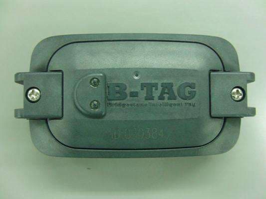
SBDB812A
Sep 16, 2014Tire Pressure Monitoring System
Equipment Class
DSC - Part 15 Security/Remote Control Transmitter
SBD11S-US
Feb 20, 201411S-US
Equipment Class
DSC - Part 15 Security/Remote Control Transmitter
SBDB812
Jun 18, 2012Tire Pressure Monitoring System
Equipment Class
DSR - Part 15 Remote Control/Security Device Transceiver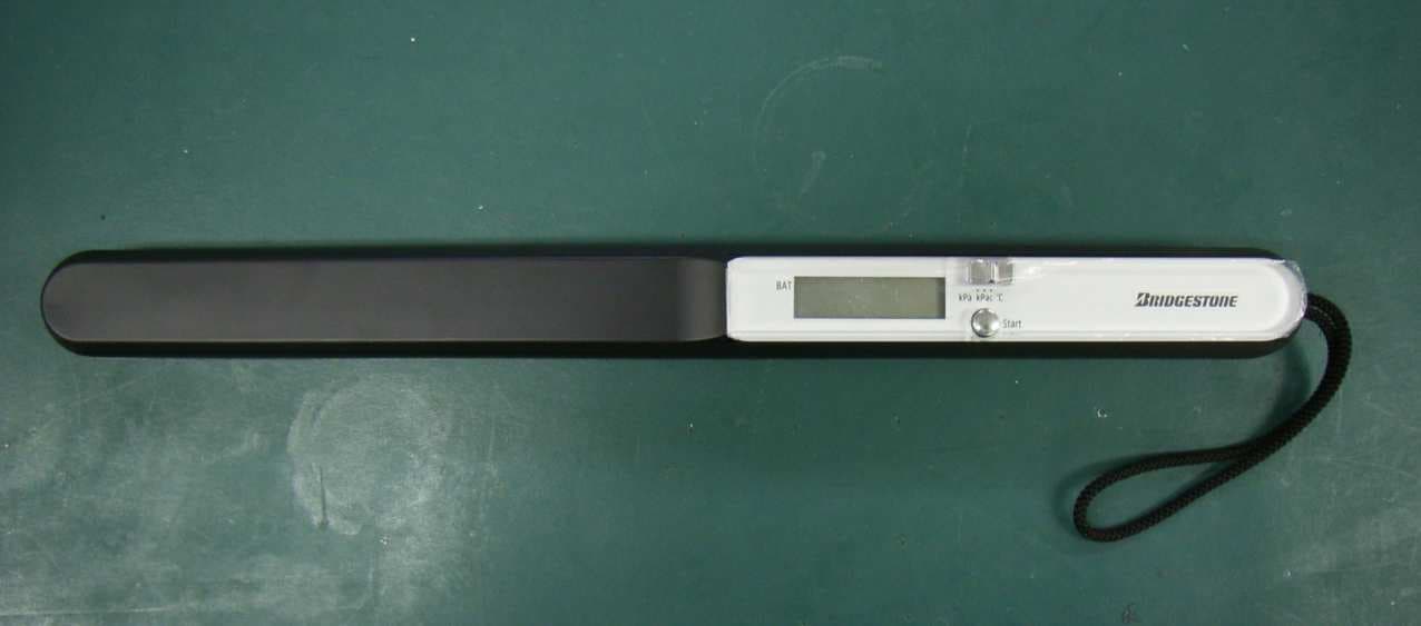
SBDK111
Dec 05, 2006TPMS Hand Reader
Equipment Class
DCD - Part 15 Low Power Transmitter Below 1705 kHz