SBDITTWB315F02Tire Sensor Module
Bridgestone Corporation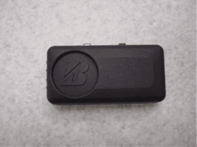
Click to zoom
Application Details
- Equipment Class
- DSC - Part 15 Security/Remote Control Transmitter
- Date of Grant
- Nov 11, 2004
- Application Purpose
- Original Equipment
- Date of Application
- Nov 11, 2004
- Equipment Note
- Tire Sensor Module
- Frequency Range
- 315.00000000 - 315.00000000
- Company
- Bridgestone Corporation
- Country
- Japan
Documents & Files
Document Text
Text extracted from the exhibit documents filed with the FCC. Open a document above to read the original.
Users Manual
PASSION for EXCELLENCE Installation The fixed method which used the valve The fixed method which used the belt Transmitter Base plate A transmitter is mounted on a base-plate. Slide in B mark B mark Slide in 1/3 PASSION for EXCELLENCE Lets a base-plate pass to a belt. Setting on a wheel Complete setting B mark B mark B mark Tire Valve B mark B mark Caution When mounting a tire for a wheel, don't make a tire collide with a transmitter. Notices This device complies with Part 15 of the FCC Rules. Operation is subject to the following two conditions: (1) This device may not cause harmful interference, and (2) this device must accept any interference received, including interference that may cause undesired operation. This equipment has been tested and found to comply with the limits for a Class B digital device, pursuant to Part 15 of the FCC Rules. These limits are designed to provide reasonable protection against harmful interference in a residential installation. This equipment generates use and can radiate radio frequency energy and, if not installed and used in accordance with instructions, may 2/3 PASSION for EXCELLENCE cause harmful interference to radio communications. However, there is no guarantee that interference will not occur in a particular installation. If this equipment does cause harmful interference to radio or television reception, which can be determined by turning the equipment off and on, the user is encouraged to correct the interference by one or more of the following measures: - Reorient or relocate the receiving antenna. - Increase the separation between the equipment and receiver. - Connect the equipment into an outlet on a circuit different from that to which the receiver is connected. - Consult the dealer or an experienced radio/TV technician for help. CHANGES OR MODIFICATIONS NOT EXPRESSLY APPROVED BY THE MANUFACTURER FOR COMPLIANCE COULD VOID THE USER’S AUTHORITY TO OPERATE THE EQUIPMENT 3/3
Cover Letter(s)
American Telecommunications Certification Body Inc. 6731 Whittier Ave, McLean, VA 22101 October 22, 2004 RE: Bridgestone Corporation FCC ID: SBDITTWB315F02 After a review of the submitted information, I have a few comments on the above referenced Application. 1) The limits for 623 and 944 MHz are not 54 dBuV/m. You may use either 15.231(e) (47.7 dBuV/m) or 15.209 (200 uV/m = 46 dBuV/m). This is significantly less than the limit used. Please correct the report. 2) Mathematical duty cycle correction is based upon a worse case 100 msec (see 15.35(c)) and not simply the period. Therefore the correction should be 20 log (43.5/100) = -7.2 dB. Please correct all affected areas of the report. 3) It is uncertain if the pulse train shown is a worse case expected pulse train regardless of the information being transmitted. Please verify with the manufacturer and if necessary, please correct. 4) Because the device is pulsed, Average measurements are not allowed (i.e. VBW 10 Hz). Average measurements many only be determined using the duty cycle correct factor calculated. Please correct. 5) Data appears to only be provided for one axis. Please confirm this is the worse case data from all 3 axis. 6) Please provide a wider plot over 1-3 seconds showing a complete set of pulse trains as being 430.5 msec. From the plots provided, it can not be adequately determined that the pulse train is this short. 7) Please make all necessary correction to both FCC and IC reports. Complete IC review will be performed once these corrections are made. 8) FYI......Regarding short term confidentiality, you are responsible for the following: a) Note that any documents held under the short-term confidentiality will automatically become public after 45 days. A manufacturer may extend this period up to an additional 45 days. This requires an additional cover letter requesting this extension must be submitted to ATCB a minimum of 7 days prior to the expiration of the original 45 day temporary grant of confidentiality b) If the manufacturer engages in public marketing activities or otherwise publicizes the device prior to the expiration of the short-term confidentiality period, the applicant must immediately notify ATCB so the exhibits can be made publicly available. Timothy R. Johnson Examining Engineer mailto: [email protected] The items indicated above must be submitted before processing can continue on the above referenced application. Failure to provide the requested information may result in application termination. Correspondence should be considered part of the permanent submission and may be viewed from the Internet after a Grant of Equipment Authorization is issued. Please do not respond to this correspondence using the email reply button. In order for your response to be processed expeditiously, you must submit your documents through the AmericanTCB.com website. Also, please note that partial responses increase processing time and should not be submitted. Any questions about the content of this correspondence should be directed to the sender.
Cover Letter(s)
American Telecommunications Certification Body Inc. 6731 Whittier Ave, McLean, VA 22101 November 12, 2004 RE: Bridgestone Corporation FCC ID: SBDITTWB315F02 After a review of the submitted information, I have a few comments on the above referenced Application. 1) FYI......For measurements > 1 GHz, you may use 54 dBuV/m average limits specified by 15.209 since they are > 47.7 dBuV/m. 2) FYI......Please show both peak (no duty cycle correction) and average (with duty cycle correction) data in future applications. This makes proofing simplier. Timothy R. Johnson Examining Engineer mailto: [email protected] The items indicated above must be submitted before processing can continue on the above referenced application. Failure to provide the requested information may result in application termination. Correspondence should be considered part of the permanent submission and may be viewed from the Internet after a Grant of Equipment Authorization is issued. Please do not respond to this correspondence using the email reply button. In order for your response to be processed expeditiously, you must submit your documents through the AmericanTCB.com website. Also, please note that partial responses increase processing time and should not be submitted. Any questions about the content of this correspondence should be directed to the sender.
Cover Letter(s)
Date: November 9, 2004 RE: Bridgestone Corporation FCC ID: SBDITTWB315F02 Dear Mr. Timothy R. Johnson, Regarding the above referenced application, please find our reply to your comments dated October 22, 2004: 1) We revised page 4 and 11 of test report. 2) As the manufacturer’s specification was worse than the actual test result, we calculated duty cycle using manufacturer’s specification. Please refer to the revised page 11 and 12 of test report. 3) We revised page 12 of test report. 4) We revised page 11 of test report. 5) Please refer to Item 5.4 on the page 7 of test report. We checked all 3 axes beforehand in order to confirm which one was the worse case. 6) Please refer to page 12 of test report where the specification provided from the manufacturer is listed. Additional Information : We found that the equipment had Alarm mode, and therefore we added the information on page 12 of test report. We hope the above reply is satisfactory. If any problems, please let us know. Best regards, Yukari Ito (Ms.) UL Apex Co., Ltd.
External Photos
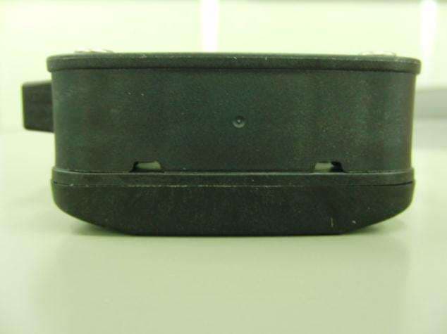
FCC ID: SBDITTWB315F02 IC No.: 5381A-YOP1010 External Photograph Top Bottom FCC ID: SBDITTWB315F02 IC No.: 5381A-YOP1010 Front Rear FCC ID: SBDITTWB315F02 IC No.: 5381A-YOP1010 Right FCC ID: SBDITTWB315F02 IC No.: 5381A-YOP1010 Left
ID Label/Location Info
FCC ID Label
Internal Photos
FCC ID: SBDITTWB315F02 IC No.: 5381A-YOP1010 Internal Photograph Side A (1) Side A (2) FCC ID: SBDITTWB315F02 IC No.: 5381A-YOP1010 Side B (1) Side B (2)
Test Report
Test report No. : 25BE0184-HO-1 Page : 2 of 14 Issued date : October 13, 2004 FCC ID : SBDITTWB315F02 Revised date : November 5, 2004 Revised date : November 29, 2004 UL Apex Co., Ltd. Head Office EMC Lab. 4383-326 Asama-cho, Ise-shi, Mie-ken 516-0021 JAPAN Telephone : +81 596 24 8116 Facsimile : +81 596 24 8124 MF060b(10.04.03) CONTENTS PAGE SECTION 1: Client information ...................................................................................................3 SECTION 2: Equipment under test (E.U.T.) ...............................................................................3 SECTION 3: Test specification, procedures & results................................................................4 SECTION 4: Operation of E.U.T. during testing ........................................................................6 SECTION 5: Radiated emission (Fundamental and Spurious Emission) .................................7 APPENDIX 1: Photographs of test setup .....................................................................................8 Radiated emission(Worst case position) ................................................................................................. 8 Worst Case Position (Horizontal : X-axis/ Vertical: X-axis)................................................................. 9 APPENDIX 2:Test Instruments .....................................................................................................10 APPENDIX 3: Data of EMI test .....................................................................................................11 Radiated Emission (Electric Field Strength of Fundamental and Spurious Emission)........................... 11 Duty Factor Calculation and Transmitting time and interval............................................................ 12 -20dB Bandwidth .................................................................................................................................... 13 Test report No. : 25BE0184-HO-1 Page : 3 of 14 Issued date : October 13, 2004 FCC ID : SBDITTWB315F02 Revised date : November 5, 2004 Revised date : November 29, 2004 UL Apex Co., Ltd. Head Office EMC Lab. 4383-326 Asama-cho, Ise-shi, Mie-ken 516-0021 JAPAN Telephone : +81 596 24 8116 Facsimile : +81 596 24 8124 MF060b(10.04.03) SECTION 1: Client information Company Name : Bridgestone Corporation. Address : 3-1-1,Ogawahigashi-Cho,Kodaira-Shi,Tokyo 187-8531 Japan Telephone Number : +81-42-342-6326 Facsimile Number : +81-42-342-6596 Contact Person : Tsutomu Nakao SECTION 2: Equipment under test (E.U.T.) 2.1 Identification of E.U.T. Type of Equipment : Sensor Module Model No. : B311 Sample No. : 0000F2 Country of Manufacture : Japan Receipt Date of Sample : September 24, 2004 Condition of EUT : Production prototype (Not for Sale: This sample is equivalent to mass-produced items.) 2.2 Product Description Model No: B311 is the Sensor Module. The clock frequency of EUT is 9.84375MHz This EUT is to measure the Tire Pressure or its temperature and transmit it as the radio wave within the fixed interval. Equipment Type : Transmitter Power Supply : DC 3.0V(BR-2450A(Lithium cell battery)) Transmitter Section Frequency operation 315MHz Type of modulation FSK Information antenna Internal / Loop antenna Receiver Section Frequency operation 125kHz Type of detection Direct detect Information antenna Internal / Transponder antenna coil FCC 15.31 (e) This EUT provides stable voltage (DC3.0V) constantly to Sensor Module regardless of input voltage. Therefore, this EUT complies with the requirement. FCC Part 15.203 Antenna requirement It is impossible for end users to replace the antenna, because the antenna is mounted inside of the EUT. Therefore, the equipment complies with the antenna requirement of Section 15.203. Test report No. : 25BE0184-HO-1 Page : 4 of 14 Issued date : October 13, 2004 FCC ID : SBDITTWB315F02 Revised date : November 5, 2004 Revised date : November 29, 2004 UL Apex Co., Ltd. Head Office EMC Lab. 4383-326 Asama-cho, Ise-shi, Mie-ken 516-0021 JAPAN Telephone : +81 596 24 8116 Facsimile : +81 596 24 8124 MF060b(10.04.03) SECTION 3: Test specification, procedures & results 3.1 Test Specification Test Specification : FCC Part 15 Subpart C 2004 Title : FCC 47CFR Part15 Radio Frequency Device Subpart C Intentional Radiators Section 15.231 Periodic operation in the band 40.66-40.70MHz and above 70MHz 3.2 Procedures and results No. Item Test Procedure Specification Deviation Worst margin Results 1 Transmitting time and Interval ANSI C63.4:2003 13. Measurement of intentional radiators Section 15.231(e) N/A - Complied 2 Electric Field Strength of Fundamental Emission ANSI C63.4:2003 13. Measurement of intentional radiators Section 15.231(e) N/A 17.5dB(AV(Pulse)) 314.969MHz Horizontal Complied 3 Electric Field Strength of Spurious Emission ANSI C63.4:2003 13. Measurement of intentional radiators Section 15.205 Section 15.209 Section 15.231(e) N/A 12.9dB(AV(Pulse)) 2.83511GHz Horizontal Complied 4 -20dB Bandwidth ANSI C63.4:2003 13. Measurement of intentional radiators Section 15.231(c) N/A - Complied 5 Conducted emission AC Mains ANSI C63.4:2003 7. AC powerline conducted emission measurements Section 15.207 N/A*1) N/A N/A Note: UL Apex’s EMI Work procedures No. QPM05 *1) The test is not applicable since the EUT is DC drive and is not connected to the public utility (AC) power line. 3.3 Addition to standards No. Item Test Procedure Specification Remarks Deviation Worst margin Results 1 99 % Occupied Band Width RSS-210(issue 5): 2001 + Amendment:2002 + Amendment2:2003 + Amendment3:2004 + Amendment4:2004 RSS-210(issue 5): 2001 + Amendment:2002 + Amendment2:2003 + Amendment3:2004 + Amendment4:2004 Conducted N/A N/A N/A 3.4 Uncertainty Radiated Emission Test The measurement uncertainty (with a 95% confidence level) for this test using Biconical antenna is + 4.5dB. The measurement uncertainty (with a 95% confidence level) for this test using Logperiodic antenna i…
Text truncated - open the document above for the full version.
Test Setup Photos
Test report No. : 25BE0184-HO-1 Page : 8 of 15 Issued date : October 13, 2004 FCC ID : SBDITTWB315F02 UL Apex Co., Ltd. Head Office EMC Lab. 4383-326 Asama-cho, Ise-shi, Mie-ken 516-0021 JAPAN Telephone : +81 596 24 8116 Facsimile : +81 596 24 8124 MF060b(10.04.03) APPENDIX 1: Photographs of test setup Radiated emission(Worst case position) Front Rear Test report No. : 25BE0184-HO-1 Page : 9 of 15 Issued date : October 13, 2004 FCC ID : SBDITTWB315F02 UL Apex Co., Ltd. Head Office EMC Lab. 4383-326 Asama-cho, Ise-shi, Mie-ken 516-0021 JAPAN Telephone : +81 596 24 8116 Facsimile : +81 596 24 8124 MF060b(10.04.03) Worst Case Position (Horizontal : X-axis/ Vertical: X-axis) X-axis Y-axis Z-axis
Contact Information
Applicant
Naoya Hamahata(Manager)
Technical Contact
UL A-Pex Co., Ltd.Makoto Kosaka
[email protected]+81-596-24-8116
4383-326 Asama-cho · Ise-shi, Mie-ken · Japan
Non-Technical Contact
UL A-Pex Co., Ltd.Yukari Ito
[email protected]+81-596-24-8116
Test Firm
UL Apex Co., Ltd.Tetsuya Hashimoto
Technical Specifications
| # | Rule Parts | Frequency Range | Power Output |
|---|---|---|---|
| 1 | 15.231(e) | 315 MHz - 315 MHz | - |
Other Applications from Bridgestone Corporation
SBDK712
May 27, 2015Tag Reader
Equipment Class
DCD - Part 15 Low Power Transmitter Below 1705 kHz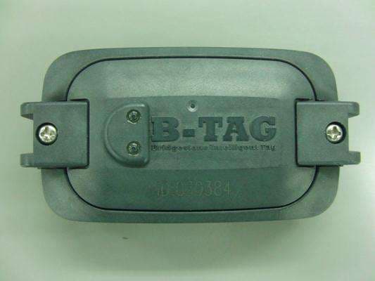
SBDB812A
Sep 16, 2014Tire Pressure Monitoring System
Equipment Class
DSC - Part 15 Security/Remote Control Transmitter
SBD11S-US
Feb 20, 201411S-US
Equipment Class
DSC - Part 15 Security/Remote Control Transmitter
SBDB812
Jun 18, 2012Tire Pressure Monitoring System
Equipment Class
DSR - Part 15 Remote Control/Security Device Transceiver
SBDK111
Dec 05, 2006TPMS Hand Reader
Equipment Class
DCD - Part 15 Low Power Transmitter Below 1705 kHz