SCD0024802.11b/g Access point
LanReady Technologies Inc.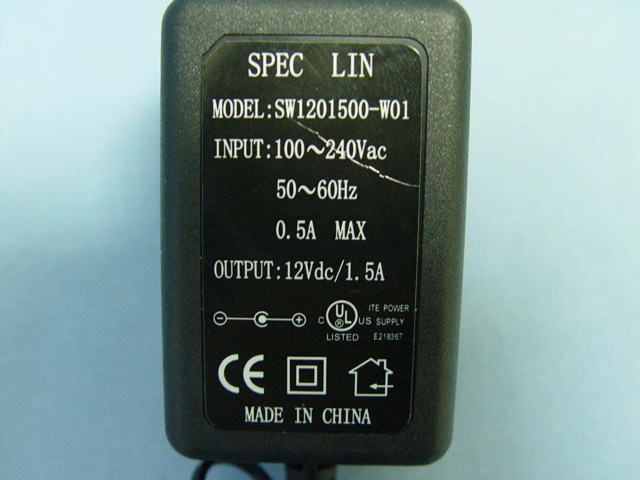
Click to zoom
Application Details
- Equipment Class
- DTS - Digital Transmission System
- Date of Grant
- Oct 02, 2005
- Application Purpose
- Original Equipment
- Date of Application
- Oct 02, 2005
- Equipment Note
- 802.11b/g Access point
- Frequency Range
- 2412.00000000 - 2462.00000000
- Company
- LanReady Technologies Inc.
- Country
- Taiwan
Documents & Files
Document Text
Text extracted from the exhibit documents filed with the FCC. Open a document above to read the original.
Users Manual
AP900 User’s Guide REV 1.2 1.0 Introduction This document is the user manual for the 5-into-1 High Gain Wireless-G Mini Access Point product. 1. Quick Start The default IP address of the 5-in-1 is 192.168.0.10. The login is “admin” and password is “password”. 1. Connect an antenna to the SMA connector closer to the LEDs. Note that there are two SMA connectors on the board. The SMA connector closer to the LEDs is required. It is optional to connect an antenna to the other connector 2. Connect the 5-into-1 to a PC using an ethernet cable. 3. Plug in the 5V power supply. 4. Make sure the PC has a IP address on the 192.168.0.xxx subnet, such as 192.168.0.100. 5. Open your web browser and navigate to 192.168.0.10. 6. Type “admin” for the login field and “password” for the password. 7. The default out-of-box operating mode is Access Point (AP) mode. To switch to Repeater, P2P, PMP or Client mode, go to the Mode page and select the desired mode. Click Apply. The board will reboot into the desired mode. 8. After the board reboots, go to the Mode page and click Setup. Configure the applicable properties for that mode, such as security, SSID, channel, etc. 9. The 5-in-1 should now be ready to use. 3. Operating Modes This section provides an overview of the All-into-1 operating mode. 3.1 Introduction to Operating Modes 3.1.1 Traveler’s AP Mode By default, the out-of-box operational mode is Access Point (AP) Mode (or Traveler’s AP Mode). When the system is reset to the default manufacturing settings, the operating mode reverts to AP Mode. In AP Mode, the system functions as a standard AP, where wireless clients connected to the AP can then connect to other wireless clients or to the wired network. For example, when traveling to a hotel that has high-speed internet access, the user can connect to the Internet through the AP which is connected to an Ethernet cable in the room (see Figure 1). The 5-into-1 AP acts only as a ISO Layer 2 bridge and does not act as a DHCP server. Therefore, it does not supply dynamic IP addresses and relies instead on the network to supply them. 3.1.2 Repeater Mode A repeater is placed between an AP and a client to extend the distance between the two WLAN devices.Functioning as a repeater, the 5-into-1 connects to both a client card as an AP and to another AP.Two repeater modes are available in the All-into-1: • WDS Repeater: WDS Repeaters connect as APs to other APs using the WDS link and MAC address to identify one another. • Universal Repeater: Universal Repeaters connect as child clients to parent APs using the SSID to connect. Figure 2 shows an example of a Repeater network with two 5-into-1 Repeaters connected to a 5-into-1 AP, with each Repeater allowing wireless clients to associate. 3.1.2.1 WDS Repeaters Wireless Distribution System (WDS) functionality is an industry standard wireless AP mode (repeater) that enables wireless bridging in which WDS APs communicate with one another using a WDS link. In typical repeater applications, APs connecting to other APs equipped with WDS functionality must also support WDS. Typically, repeaters will not function properly with other APs that are not equipped with WDS. Figure 3 shows an example of a WDS Repeater network with 5-into-1 Repeaters in Parent/Child configurations with other Repeaters. 3.1.2.2 Universal Repeaters When configured as a Universal Repeater, the 5-into-1 allows connectivity to APs that are not equipped with WDS. Figure 4 shows an example of a WDS Repeater network. 3.1.3 Point-to-Point (P2P) Mode Two 5-into-1 devices, each in Point-to-Point (P2P) Mode, establish a wireless connection between two wired networks, as shown in Figure 5. The two 5-into-1 devices operating in P2P Mode do not allow client associations. To configure the 5-into-1 devices to establish a P2P wireless bridge, ensure the following: 1. Enter the MAC address of P2P-2 device in the P2P MAC address field in the P2P-1 device. 2. Enter the MAC address of P2P-1 device in the P2P MAC address field in the P2P-2 device. 3.1.4 Point-to-Multipoint (PMP) Mode An 5-into-1 device operating in Point-to-Multipoint (PMP) Mode wirelessly connects two or more wired networks, as shown in Figure 6. The root 5-into-1 device (LAN1) operates in PMP Mode, while the other 5-into-1 devices (LAN2, LAN3) must operate in P2P Mode. When operating in PMP Mode, the 5-into-1 device does not allow client associations. The user must enter the MAC addresses (up to six) of each P2P device into the PMP system table of Remote AP MAC addresses. 3.1.5 Client Mode When set to Client Mode, the 5-into-1 device associates with an AP within its range. Figure 7 shows the Client Mode 5-into-1 operating as a wireless client in infrastructure mode. Figure 8 shows the Client Mode 5-into-1 joined with another Client Mode 5-into-1 device in an Ad-Hoc network. The Client behaves like a normal wireless client. 4. Wireless Security Support The 5-into-1 supports wireless encryption as shown in Table1. Table 1: Wireless Security Mode WEP WPA-PSK WPA2 WPA/WPA2 Mixed AP Yes Yes Yes Yes Repeater (WDS) Yes No No No Repeater (Universal) Yes Yes No No P2P Yes No No No PMP Yes No No No Client (Infrastructure) Yes Yes No No Client (Ad-Hoc) Yes No No No 5. Mode Selection The first step in using the 5-into-1 is selecting the operating mode. The default operating mode is AP Mode. To view the web page for the device, open a web browser and enter 192.168.0.10 (default IP address of the device) as the URL. The default username is “admin” and the default password is “password.” Figure 9 shows the page displayed once logged in. To select a mode, click the Mode tab. Click the radio button next to the desired mode and click the Apply button. The device will reboot in the selected mode. After the board reboots, click the Setup button to begin configuring the device. The “What’s This?” button opens a popup window with a brief description of each mode . Figure 9:Mode Page 6. AP Setup 6.1 Basic Setup To configure the …
Text truncated - open the document above for the full version.
External Photos
Compliance Certification Services Inc. Report No: 50308001 Date of Issue: September 6, 2005 Page 1 Total Page: 8 Rev. 00 EXTERNAL PHOTOGRAPHS OF EUT LanReady / AP900+ Compliance Certification Services Inc. Report No: 50308001 Date of Issue: September 6, 2005 Page 2 Rev. 00 Compliance Certification Services Inc. Report No: 50308001 Date of Issue: September 6, 2005 Page 3 Rev. 00 OvisLink / WL-5430AP Compliance Certification Services Inc. Report No: 50308001 Date of Issue: September 6, 2005 Page 4 Rev. 00 Pheenet / WAP-454G Compliance Certification Services Inc. Report No: 50308001 Date of Issue: September 6, 2005 Page 5 Rev. 00 Astarte / ASR9000
ID Label/Location Info
This device complies with Part 15 of the FCC Rules. Operation is subject to the following two conditions: (1) this device may not cause harmful interference and (2) this device must accept any interference received, including interference that may cause undesired operation. Model Name : AP900+ Serial No. Made in Taiwan LanReady FCC ID: SCD0024
Internal Photos
Compliance Certification Services Inc. Report No: 50308001 Date of Issue: September 6, 2005 Page 6 Rev.00 INTERNAL PHOTOGRAPHS OF EUT Compliance Certification Services Inc. Report No: 50308001 Date of Issue: September 6, 2005 Page 7 Rev.00 Compliance Certification Services Inc. Report No: 50308001 Date of Issue: September 6, 2005 Page 8 Rev.00 Compliance Certification Services Inc. Report No: 50308001 Date of Issue: September 6, 2005 Page 9 Rev.00
Parts List/Tune Up Info
APVDCHKDDSGD SPECIFICATION PRODUCT CODE: TT98024 2005.01.26 2005.01.25 2005.01.25 1. General: 1.1 Scope This specification is applied for fixed 1/2 Dipole antenna. (Type 2.4GHz external standard dipole antenna.) 1.2 Operating Temperature -10+75 1.3 Storage Temperature -20+75 1.4 Test conditions Standard test conditions should be from 5 to 35 in temperature , 45 to 85%RH and 860 to 1060 hpa in barometric pressure. Should conducted at 202,655%RH and 860 to 1060 hpa. 2. Appearances, structures and dimensions: 2.1 Appearances Finished on each part should be good, functionally free from rust, Crack and scratch. 2.2 Structures and dimensions They are produced according to the drawing of individual product. 3. Electrical performance: PropertyTest conditionsPerformance VSWR< 2.0 3.1 Frequency Range Proving the suitable test ,according to custamer’s request and all the necessary condition of the set. 2400-2500MHz 3.2Impedance 502 ohms 3.3DirectionalOmni 3.4Antenna gain0.6~2.0 dBi 3.5Tolerance power1w 4.Material specification: ItemMaterialCharacteristic CoverThermal Plastic ElastormerHardness:65 (Gray) WireRG178 Coaxial CableTint Brown 5.Coaxial Cable Charcterictic: 5.1.Mechanical characterisitics MaterialSCCS Composition(N/M)7/0.08mm Center conductor O.D.0.30mm MaterialPTFEDielectric O.D.0.83Min MaterialSPC Coverage85%Min Braided Shield Strands 0.06mm MaterialFEPJacket O.D.1.89mm 5.2. Electric data ItemSpecificationUnit Capacitance85PF/M Impedance50 ± 2 Attenuation3.5(3GHz)Db/M 6.Weather ability: PropertyTest conditionPerformance 6.1Dry heat proof After leaving 96 hours at temperature 752,leave 1 hour in a normal ambient condition and measure. Clean the appearance before test. There shall be no detects on cover broken or antenna drop out, satisfy item-3. 6.2Cold proof After leaving 96 hours at temperature –302,leave 1 hour in a normal ambient condition and measure. Clean the appearance before test. There shall be no detects on cover broken or antenna drop out, satisfy item-3. 6.3Damp heat proof After leaving 96 hours at temperature 403 and 90 to 95%RH,leave 1 hour in a normal ambient condition and measure. Clean the appearance before test. There shall be no detects on cover broken or antenna drop out, satisfy item-3. 7.Sample dependability(O.C Standard ): According to MIL-STD-105D (About 1/200 pcs ungainly to repeal one lot in all quantity.) 8.Measurement instrument: 8.1 PC SIZE: PC-9801FA (NEC) 8.2 Room size: 400cm (W)X350cm(H)X630cm(L) 8.3 Net work analyzer: Test equipment on electrical functions Equipment by Hewlett Packard, Network Analyzer HP-8752A by Advantest, Network Analyzer R3767CG 9.Packing Instructions: One parcel bag contain = 15 pcs One middle box contain = 14 parcel bags (15 pcs x 14 parcel bags =210 pcs) One master carton contains =3 middle boxs (3x middle boxs = 630 pcs) M M e e a a s s u u r r e e m m e e n n t t C C o o n n d d i i t t i i o o n n D D i i a a g g r r a a m m (1).Electrical Performance Measurement: (2).Radiation Pattern Measurement: P P e e r r f f o o r r m m a a n n c c e e D D a a t t a a S S h h e e e e t t (1).Electrical Performance Data: P P e e r r f f o o r r m m a a n n c c e e D D a a t t a a S S h h e e e e t t (2).Vertical-Plane Radiation Pattern Data: P P e e r r f f o o r r m m a a n n c c e e D D a a t t a a S S h h e e e e t t (3). Horizontal-Plane Radiation Pattern Data:
Parts List/Tune Up Info
200.0 1.0mm 25.80 1 2 . 9 0 1 3 . 0 W301-200-D200 2.4-2.5Ghz 5dBi Antnna 1 1 1/1 W301-200-D200 A Yang04/14/03 Yang04/14/03 SAMPLE NEW RELEASE Yang Yang 2003/04/14 2003/04/14 03-161 1 2 3 4 5 03-249 Yang 2003/06/02 6 B SEE ECN ELECTRICAL PERFORMANCE :1.Impedance : 50 ohms2.Frequency Range :2.4--2.5 GHz3.VSWR : 2.0 maximum4.Gain :5dbimax1 REV. A DESCRIPTION ECN REVISIONS DRAWN DATE O I INPUT OUTPUT REMARKS TOLERANCES: DIM. X.X=±0.5 UNIT:mm TITLE:DESIGNED: CHECKED: DRAWN: APPROVAL: SHEET:DWG NO. :LAYER: SCALE:REV. P/No. : X.XX=±0.25 OF RP SMA BRASS GOLD4u" Shell ABS Black BRASS Black Cr ABS Black ABS Black TPR Black ITEM Description Materials Finshed Q'ty ANTENNA TEST NO. W301-200-D200TEST DATE:2003/06/17TEST FREQUECY:2450MhzTEST POLARIZATION:HORIZTAL (E-PLANE) TEST ANTENNA:HORN ANTENNATEST CHAMBER:RF CHAMBERTEST PERSONNEL: YangMAX GAIN: dBi MIN GAIN: dBi AVE GAIN: dBi ANTENNA TEST NO.WW301-200-D200TEST DATE:2003/06/17TEST FREQUENCY:2450MhzTEST POLARIZATION:VERTICAL (H-PLANE) TEST ANTENNA:HORN ANTENNATEST CHAMBER:RF CHAMBERTEST PERSONNEL: YangMAX GAIN: dBi MIN GAIN: dBi AVE GAIN: dBi
Test Report
Compliance Certification Services Inc. Report No.: 50308001-RP1 FCC ID: SCD0024 Date of Issue: September 6, 2005 Note: This report shall not be reproduced except in full, without the written approval of Compliance Certification Services Inc. This document may be altered or revised by Compliance Certification Services Inc. personnel only, and shall be noted in the revision section of the document. Page 1 Total Page: 61 Rev. 00 FCC 47 CFR PART 15 SUBPART C TEST REPORT For 802.11b/g Access point Trade Name / Model LanReady / AP900+ OvisLink / WL-5430AP Pheenet / WAP-454G Astarte / ASR9000 Issued to LanReady Technologies Inc. 4F, No. 337, Sinhu 2nd Rd., Neihu District, Taipei City 114, Taiwan (R.O.C.) Issued by Compliance Certification Services Inc. No. 81-1, Lane 210, Bade Rd. 2, Luchu Hsiang, Taoyuan Hsien, (338) Taiwan, R.O.C. TEL: 886-3-324-0332 FAX: 886-3-324-5235 Compliance Certification Services Inc. Report No.: 50308001-RP1 FCC ID: SCD0024 Date of Issue: September 6, 2005 Page 2 Rev. 00 TABLE OF CONTENTS 1. TEST RESULT CERTIFICATION....................................................................................................3 2. EUT DESCRIPTION ...........................................................................................................................4 3. TEST METHODOLOGY ....................................................................................................................5 3.1 EUT CONFIGURATION........................................................................................................................5 3.2 EUT EXERCISE....................................................................................................................................5 3.3 GENERAL TEST PROCEDURES.............................................................................................................5 3.4 FCC PART 15.205 RESTRICTED BANDS OF OPERATIONS........................................................6 3.5 DESCRIPTION OF TEST MODES...........................................................................................................6 4. INSTRUMENT CALIBRATION........................................................................................................7 4.1 MEASUREMENT EQUIPMENT USED.........................................................................................7 5. FACILITIES AND ACCREDITATIONS ..........................................................................................8 5.1 FACILITIES .........................................................................................................................................8 5.2 EQUIPMENT........................................................................................................................................8 5.3 LABORATORY ACCREDITATIONS AND LISTING..................................................................................8 5.4 TABLE OF ACCREDITATIONS AND LISTINGS.......................................................................................9 6. SETUP OF EQUIPMENT UNDER TEST .......................................................................................10 6.1 SETUP CONFIGURATION OF EUT.......................................................................................................10 6.2 SUPPORT EQUIPMENT ...............................................................................................................10 7. FCC PART 15.247 REQUIREMENTS.............................................................................................11 7.1 6DB BANDWIDTH.............................................................................................................................11 7.2 PEAK POWER....................................................................................................................................16 7.3 AVERAGE POWER............................................................................................................................21 7.4 BAND EDGES MEASUREMENT ................................................................................................26 7.5 PEAK POWER SPECTRAL DENSITY....................................................................................................35 7.6 RADIO FREQUENCY EXPOSURE........................................................................................................40 7.7 SPURIOUS EMISSIONS ................................................................................................................42 7.8 POWERLINE CONDUCTED EMISSIONS...............................................................................................56 APPENDIX 1 PHOTOGRAPHS OF TEST SETUP ..............................................................................59 Compliance Certification Services Inc. Report No.: 50308001-RP1 FCC ID: SCD0024 Date of Issue: September 6, 2005 Page 4 Rev. 00 2. EUT DESCRIPTION Product 802.11b/g Access point Trade Name / Model Number LanReady / AP900+ OvisLink / WL-5430AP Pheenet / WAP-454G Astarte / ASR9000 Model Discrepancy All the specification and layout are identical except they come with different trade names, model numbers and colors. Please refer to the EUT photos for detail descriptions. Power Supply Model number: SW1201500-W01 I/P: AC 100-240V, 0.5A, 50-60Hz O/P: DC 12V, 1.5A Frequency Range 2412 ~ 2462 MHz Transmit Power IEEE 802.11b: 19.50 dBm IEEE 802.11g: 13.91 dBm Modulation Technique IEEE 802.11b: DSSS (CCK, DQPSK, DBPSK) IEEE 802.11g: DSSS (CCK, DQPSK, DBPSK) + OFDM (QPSK, BPSK, 16-QAM, 64-QAM) Transmit Data Rate IEEE 802.11b: 11, 5.5, 2, 1 Mbps IEEE 802.11g: 54, 48, 36, 24, 18, 12, 11, 9, 6, 5.5, 2, 1 Mbps Number of Channels 11 Channels Antenna Specification P/No.: W301-200-D200 / 5 dBi P/No.: TT98024 / 2dBi Antenna Designation Dipole Antenna Remark: 1. The sample selected for test was engineering sample that approximated to production product and was provided by manufacturer. 2. This submittal(s) (tes…
Text truncated - open the document above for the full version.
Test Setup Photos
Compliance Certification Services Inc. Report No.: 50308001-RP1 FCC ID: SCD0024 Date of Issue: September 6, 2005 Page 59 Rev. 00 APPENDIX 1 PHOTOGRAPHS OF TEST SETUP Conducted Emissions Setup Photos Compliance Certification Services Inc. Report No.: 50308001-RP1 FCC ID: SCD0024 Date of Issue: September 6, 2005 Page 60 Rev. 00 Radiated Emissions Setup Photos Compliance Certification Services Inc. Report No.: 50308001-RP1 FCC ID: SCD0024 Date of Issue: September 6, 2005 Page 61 Rev. 00 Powerline Conducted Emissions Setup Photos
Contact Information
Applicant
Spencer Chen
Test Firm
Compliance Certification Services Inc.Kurt Chen
Technical Specifications
| # | Rule Parts | Frequency Range | Power Output |
|---|---|---|---|
| 1 | 15C | 2.41 GHz - 2.46 GHz | 89.10 mW |
Other Applications from LanReady Technologies Inc.
SCDIW181000001
May 12, 2014802.11n 1x1 In-Wall access Point
Equipment Class
DTS - Digital Transmission System
SCDOW161000001
Jan 06, 2014AP Router
Equipment Class
DTS - Digital Transmission System
SCDOW141000001
Aug 08, 2013AP Router
Equipment Class
DTS - Digital Transmission System
SCDDS505
Dec 09, 20125-Ports 10/100/1000 Mbps Green Switch
Equipment Class
JBP - Part 15 Class B Computing Device Peripheral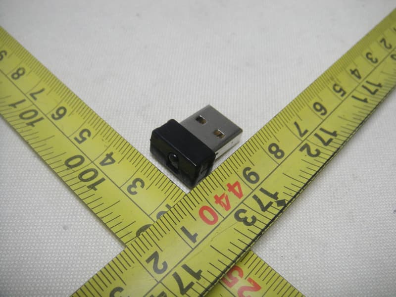
SCD030025
Oct 10, 2011USB Wireless Adapter
Equipment Class
DTS - Digital Transmission System