SCD020063802.11a/n AP (Master)
LanReady Technologies Inc.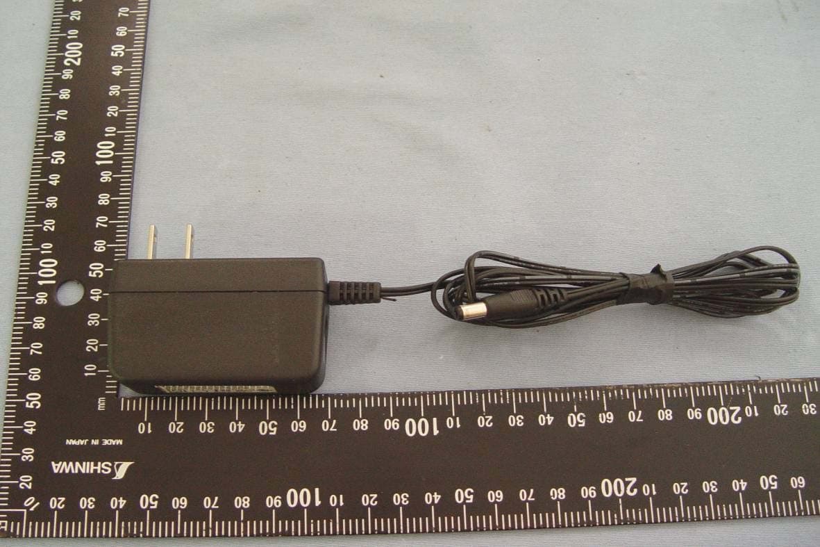
Click to zoom
Application Details
- Equipment Class
- DTS - Digital Transmission System
- Date of Grant
- Apr 19, 2010
- Application Purpose
- Original Equipment
- Date of Application
- Apr 19, 2010
- Equipment Note
- 802.11a/n AP (Master)
- Frequency Range
- 5755.00000000 - 5795.00000000
- Company
- LanReady Technologies Inc.
- Country
- Taiwan
Documents & Files
Document Text
Text extracted from the exhibit documents filed with the FCC. Open a document above to read the original.
Users Manual
LanReady WCB1200H5PX User Manual V2.0.3-FCC Table of Contents Chapter 1. System Overview ............................................................................................................. 1 1.1 Introduction of WCB1200H5PX.................................................................................................. 1 1.2 System Concept......................................................................................................................... 2 1.3 Applications in Wireless Network ............................................................................................... 3 1.4 Product Benefit .......................................................................................................................... 7 1.5 Specification ............................................................................................................................... 8 Chapter 2. Basic Installation ........................................................................................................... 12 2.1 Hardware Installation ............................................................................................................... 12 2.1.1 Package Contents............................................................................................................. 12 2.1.2 Panel Function Descriptions ............................................................................................. 12 2.1.3 Hardware Installation Steps ..............................................................................................13 2.2 Web Management Interface Instructions.................................................................................. 14 Chapter 3. AP Mode Configuration ................................................................................................. 15 3.1 External Network Connection................................................................................................... 15 3.1.1 Network Requirement .......................................................................................................15 3.1.2 Configure LAN IP .............................................................................................................. 16 3.2 Wireless LAN Network Creation...............................................................................................18 3.2.1 Wireless General Setup ....................................................................................................18 3.2.2 Wireless Advanced Setup ................................................................................................. 20 3.2.3 Create Virtual AP (VAP) .................................................................................................... 26 3.2.3.1 Virtual AP Overview ................................................................................................... 26 3.2.3.2 Virtual AP Setup......................................................................................................... 27 3.2.4 Wireless MAC Filter Setup ................................................................................................31 3.3 Wireless Network Expansion ................................................................................................... 32 3.4 System Management ............................................................................................................... 33 3.4.1 Configure Management .................................................................................................... 33 3.4.2 Configure System Time.....................................................................................................36 3.4.3 Configure SNMP Setup.....................................................................................................37 3.4.4 Backup / Restore and Reset to Factory ............................................................................ 39 3.4.5 Firmware Upgrade ............................................................................................................ 40 3.4.6 Network Utility ................................................................................................................... 41 3.4.7 Reboot.............................................................................................................................. 42 3.5 System Status .......................................................................................................................... 43 3.5.1 System Overview .............................................................................................................. 43 3.5.2 Associated Clients Status.................................................................................................. 46 3.5.3 Show WDS Link Status .....................................................................................................47 3.5.4 Extra Information............................................................................................................... 48 3.5.5 Event Log.......................................................................................................................... 50 Chapter 4. WDS Mode Configuration..............................................................................................51 4.1 External Network Connection................................................................................................... 51 4.1.1 Network Requirement .......................................................................................................51 4.1.2 Configure LAN IP .............................................................................................................. 52 4.2 Wireless Network Expansion ................................................................................................... 53 4.2.1 General Setup................................................................................................................... 5…
Text truncated - open the document above for the full version.
Users Manual
User Manual WCB1200H5PX Wireless High Power 5.8Ghz CPE 111 While creating multiple Virtual Server rules, the prior rules have higher priority. The Virtual server rules have precedence over the DMZ one while both rules exist. Example 1 and 2 demonstrate proper usage of DMZ and Virtual Server rules. Example 1 : All connections should be redirected to 192.168.2.12 while DMZ is enabled. Since Virtual Server rules have precedence over the DMZ rule all connections to TCP port 22 will be directed to TCP port 22 of 192.168.2.10 and remaining connections to port TCP 20~80 will be redirected to port TCP 20~80 of 192.168.2.11 DMZ Enabled : 192.168.2.12 Rule Protocol Private IP Private Port Public Port 1 TCP 192.168.2.10 22 22 2 TCP 192.168.2.11 20:80 20:80 Example 2 : All connections should be redirected to 192.168.2.12 while DMZ is enabled. Since Virtual Server rules have precedence over the DMZ rule all other connections to TCP port 20~80 will be redirected to port 20~80 of 192.168.2.11. The rule 2 won’t take effect. DMZ Enabled : 192.168.2.12 Rule Protocol Private IP Private Port Public Port 1 TCP 192.168.2.11 20:80 20:80 2 TCP 192.168.2.10 22 22 User Manual WCB1200H5PX Wireless High Power 5.8Ghz CPE 112 5.6 System Status This section breaks down into subsections of System Overview, Station Statistics, Extra Information and Event Log. 5.6.1 Overview Detailed information on System, WAN Information, LAN Information and DHCP Server Status can be reviewed via this page. System : Display the information of the system. Î System Name : The name of the system. Î Operating Mode : The mode currently in service. Î Location : The reminding note on the geographical location of the system. Î Description : The reminding note of the system. Î Firmware Version : The current firmware version installed. Î Firmware Date : The build time of the firmware installed. Î Device Time : The current time of the system. Î System Up Time : The time period that system has been in service since last reboot. WAN Information : Display the information of the WAN interface. The WAN port specified Dynamic IP, the Release and Renew button will be show-up, click Release button to release IP address of WAN port, Renew button to renew IP address through DHCP server. User Manual WCB1200H5PX Wireless High Power 5.8Ghz CPE 113 The WAN port specified PPPoE or PPTP, and the Connect and DisConnect button will be show up. Click “Connect” button to assigned IP address from PPPoE or PPTP server, “DisConnect” button to release IP address of WAN port. Î Mode : Supports Static, Dynamic, PPPoE and PPTP modes. Î Reconnect Mode : The current reconnect mode of the PPPoE or PPTP. Î MAC Address : The MAC address of the WAN port. Î IP Address : The IP address of the WAN port. Î IP Netmask : The IP netmask of the WAN port. Î IP Gateway : The gateway IP address of the WAN port. Î Primary DNS : The primary DNS server in service. Î Secondary DNS : The secondary DNS server in service. Î Receive bytes : The total received packets in bytes on the WAN port. Î Receive packets : The total received packets of the WAN port. Î Transmit bytes : The total transmitted packets in bytes of the WAN port. Î Transmit packets : The total transmitted packets of the WAN port. LAN Information : Display total received and transmitted statistics on the LAN interface. Î MAC Address : The MAC address of the LAN port. Î IP Address : The IP address of the LAN port. Î IP Netmask : The IP netmask of the LAN port. Î Receive bytes : The total received packets in bytes on the LAN port. Î Receive packets : The total received packets of the LAN port. Î Transmit bytes : The total transmitted packets in bytes of the LAN port. Î Transmit packets : The total transmitted packets of the LAN port. User Manual WCB1200H5PX Wireless High Power 5.8Ghz CPE 114 DHCP Server Status : Users could retrieve DHCP server and DHCP clients’ IP/MAC address via this field. Î IP Address : IP addresses to LAN devices by DHCP server. Î MAC Address : MAC addresses of LAN devices. Î Expired In : Shows how long the leased IP address will expire. User Manual WCB1200H5PX Wireless High Power 5.8Ghz CPE 115 5.6.2 Station Statistics Link information, Transmit and Receive Statistics for the connection with AP, Below depicts an example for Station Statistics. Link Status : Î Status : Shows the current link status. It should be “Connected” or “Disconnected”. Î ESSID : Shows the current SSID, which must be the same on the wireless client and AP in order for communication to be established. Î BSSID : Shows the associated BSSID, which can be used to identify the wireless access point. Î Extra Info : Shows the current link status of extra information. It should be “Link is Up” or “Link is Down”, Î Channel : Shows current channel and central channel, its corresponding frequency. Î Link Speed(Mbps) : The data transfer speed adopted by this network. (measured in Mbits per second) Î Link Quality : Shows the link quality of the system with an access point. Î Signal Strength ANT0/ANT1 : Shows the wireless signal strength of the connection between system and an access point. HT Status : Î Channel BandWidth : Shows the current channel bandwidth used for communication. It should be “20” or “40” Î Guard Interval : Shows the current GI used for communication. It should be “short” or “long”. Î MCS : Shows the current GI used for communication. It should be between 0 to 15 or 32. Transmit Statistics Î Frames Transmitted Successfully: The number of successfully transmitted frames. Î Frames Transmitted Successfully Without Retry: The number of successfully transmitted frames without any retry. Î Frames Transmitted Successfully After Retry(s): The number of successfully transmitted frames with one or more retries. User Manual WCB1200H5PX Wireless High Power 5.8Ghz CPE 116 Î Frames Fail To Receive ACK After All Retries: The number of unsuccessfully transmitted frame with many retries. Î RTS Frames Successfully Receive CTS: The numbe…
Text truncated - open the document above for the full version.
Users Manual
User Manual WCB1200H5PX Wireless High Power 5.8Ghz CPE 201 7.4.5 Firmware Upgrade Firmware is the main software image that system needs to respond to requests and to manage real time operations. Firmware upgrades are sometimes required to include new features or bugs fix. It takes around 2 minutes to upgrade due to complexity of firmware. To upgrade system firmware, click Browse button to locate the new firmware, and then click Upgrade button to upgrade. 1. To prevent data loss during firmware upgrade, please back up current settings before proceeding 2. Do not interrupt during firmware upgrade including power on/off as this may damage system. 3. Never perform firmware upgrade over wireless connection or via remote access connection. User Manual WCB1200H5PX Wireless High Power 5.8Ghz CPE 202 7.4.6 Network Utility The administrator can diagnose network connectivity via the PING utility. Please click on Utilities -> Network Utility and follow the below setting. Ping : This utility will help ping other devices on the network to verify connectivity. Ping utility, using ICMP packets, detects connectivity and latency between two network nodes. As result of that, packet loss and latency time are available in the Result field while running the PING test. Î Destination IP/Domain : Enter desired domain name, i.e. www.google.com, or IP address of the destination, and click ping button to proceed. The ping result will be shown in the Result field. Î Count : By default, it’s 5 and the range is from 1 to 50. It indicates number of connectivity test. Traceroute : Allows tracing the hops from the WCB1200H5PX device to a selected outgoing IP address. It should be used for the finding the route taken by ICMP packets across the network to the destination host. The test is started using the Start button, click Stop button to stopped test Î Destination Host : Specifies the Destination Host for the finding the route taken by ICMP packets across the network. Î MAX Hop : Specifies the maximum number of hops( max time-to-live value) traceroute will probe. User Manual WCB1200H5PX Wireless High Power 5.8Ghz CPE 203 7.4.7 Reboot This function allows user to restart system with existing or most current settings when changes are made. Click Reboot button to proceed and take around three minutes to complete. A reminder will be available for remaining time to complete. If power cycle is necessary, please wait till completion of the reboot process. The System Overview page appears upon the completion of reboot. User Manual WCB1200H5PX Wireless High Power 5.8Ghz CPE 204 7.5 System Status This section breaks down into subsections of System Overview, Associated Clients Status, Remote AP, Extra Information and Event Log. 7.5.1 System Overview Display detailed information of System, Network, LAN and Wireless in the System Overview page. System : Display the information of the system. Î System Name : The name of the system. Î Operating Mode : The mode currently in service. Î Location : The reminding note on the geographical location of the system. Î Description : The reminding note of the system. Î Firmware Version : The current firmware version installed. Î Firmware Date : The build time of the firmware installed. Î Device Time : The current time of the system. Î System Up Time : The time period that system has been in service since last reboot. Network Information : Display the information of the Network. Î Mode : Supports Static or Dynamic modes on the LAN interface. Î IP Address : The management IP of system. By default, it’s 192.168.2.254. Î IP Netmask : The network mask. By default, it’s 255.255.255.0. Î IP Gateway : The gateway IP address and by default, it’s 192.168.2.1. Î Primary DNS : The primary DNS server in service. Î Secondary DNS : The secondary DNS server in service. User Manual WCB1200H5PX Wireless High Power 5.8Ghz CPE 205 LAN Information : Display the detailed receive and transmit statistics of LAN interface. Î MAC Address : The MAC address of the LAN port. Î Receive bytes : The total received packets in bytes on the LAN port. Î Receive packets : The total received packets of the LAN port. Î Transmit bytes : The total transmitted packets in bytes of the LAN port. Î Transmit packets : The total transmitted packets of the LAN port. Wireless Information : Display the detailed receive and transmit statistics of Wireless interface. Î AP MAC Address : The MAC address of the repeater AP. Î Station MAC Address : The MAC address of the Wireless Client Station. Î Channel : The current channel on the Wireless port. Î AP Rate : The current Bit Rate on the Repeater AP. Î Station Rate : The current Bit Rate on the Wireless Client Station. Î Receive bytes :The total received packets in bytes on the Wireless port. Î Receive packets : The total received packets on the Wireless port. Î Transmit bytes : The total transmitted packets in bytes on the Wireless port. Î Transmit packets : The total transmitted packets on the Wireless port. User Manual WCB1200H5PX Wireless High Power 5.8Ghz CPE 206 DHCP Server Status : Users could retrieve DHCP server and DHCP clients’ IP/MAC address via this field. Î IP Address : IP addresses to LAN devices by DHCP server. Î MAC Address : MAC addresses of LAN devices. Î Expired In : Shows how long the leased IP address will expire. User Manual WCB1200H5PX Wireless High Power 5.8Ghz CPE 207 7.5.2 Associated Clients Status It displays ESSID, on/off Status, Security Type, total number of wireless clients associated with Repeater AP. AP Information : Highlights key Repeater AP information. Î AP : Available Repeater AP. Î ESSID : Display name of ESSID for Repeater AP. Î MAC Address : Display MAC address for Repeater AP. Î Status : On/Off Î Security Type : Display chosen security type; WEP, WPA/WPA2-PSK, WPA/WPA2-Enterprise. Î Clients : Display total number of wireless connections on Repeater AP. Repeater AP Clients : Display all associated clients. Î MAC Address : MAC address of assoc…
Text truncated - open the document above for the full version.
Attestation Statements
MODEL: OA-515912 5.1GHz - 5.9 GHz 12dBi High Gain & Wide Band Omni-Directional Antenna APPLICATIONS AND FEATURES Applications: Features : SPECIFICATIONS: Electrical Specifications Frequency Range 5100 – 5900 MHz V.S.W.R1.5 Return Loss -15db Antenna Type Collinea Gain 12dBi Polarization Vertical Maximum Power 50W Vertical Beam-with 10 Deg Horizontal Beam-with 360 Deg Impedance 50 Ohm Connector N-Female Mechanical Specifications z 5.1 – 5.9 GHz ISM Band z 5.3 GHz Band Applications z 5.4 GHz Band Applications z 5.8GHz UNII applications z IEEE 802.11a Wireless LAN z Unlicensed European 5.4 GHz Band Applications z WiMAX Technology z 5.8 GHz Wireless Video Systems z Superior performance z Light weight z All weather operation z DC Short lightning protection z Installed for vertical z Includes tilt and swivel mast mount z Frequency Ultra-wide z Can be installed for either vertical or horizontal polarization z RoHS Compliant The OA-515912 belongs to Omni-Directional antennas, can be used in an outdoors type a base set an usage, the antenna OA-515912 usage uses in the frequency scope of the 5.1~5.9 GHz(the Wireless LAN of the IEEE 802.11a) The antenna OA-515912 adoption aluminum pushes a type(anode inside), antenna tube adoption glass fiber manufacturing, in order to can insure the enduring of product and adapt various environment, the antenna also adopts the most convenient construction method on the gearing, making a convenience of an user to install quickly, The OA-515912 guards a pass through strict process while producing construction manufacturing, at various waterproof characteristic and the radiation characteristic, pass by strict of test The antenna includes mounting bracket and hardware for up to 2” OD masts. Made with fiberglass and comes with an integrated N Female connector. Length 570mm Diameter 68mm Weight 450g Wind Survival 150 MPH Radome Material White Fiberglass Operating Temperature 40 to 80 Clamps U-bolt Mounting 32 – 45mm RoHS Compliant Ye s OA-515912 Test Report 5.1GHz - 5.9 GHz 12dBi High Gain & Wide Band Omni-Directional Antenna Retuen loss & V.S.W.R Retuen loss V. S . W. R Antenna Vertical & Horzontal Pattern Horizontal H-plane co-pol ------ 3-dB beam-with=360 Deg Vertical E-plane co-pol ------ 3-dB beam-with=8 Deg Fei Teng Wireless Technology Corp. 6F.,NO 10-10.Guangming 9st RD.,Jhubei city. Hsinchu conutry302,Taiwan TEL:886-3-5585239 FAX:886-3-5585143 http://www.FT-RF.com e-mail:[email protected] OA-515912 Antenna Outward Appearance Chart OA-515912 Mounting Kits Installation Guide
Attestation Statements
Model No.: MA5G14DP 5GHz 14dBi Dual-Polarization CPE Antenna Module (Prelimitary) MA5G14DP is a 14 dBi Dual Polarization Outdoor/Indoor Directional Antenna module amplifies your Outdoor WiF-N AP/Birdge wireless signal in a concentrated direction. The directional design of antenna module with 2 RF connector that creates the Vertical and Horizontal transmit/reciving at same time . MA5G14DP may amplified wireless-N (MIMO) signal that extend the coverage of a wireless local area network . Features High gain: 14.84 dBi Frequency : 5.150 – 5.825GHz Support Dual Polarization ( Vertical and Horizontal ) Two RF Connector For Wireless-n (MIMO ) Application Increase your Wireless Network Strength Target Customer Outdoor / Indoor Wireless System Integrator Outdoor / Indoor Surveillance IP Camera System Provider Outdoor /Indoor Industrial Automation System Integrator Outdoor /Indoor Wireless Control System Integrator Application Outdoor / Indoor long range Point to Point Outdoor / Indoor long range CPE / Client Bridge Outdoor / Indoor long range Wireless IP Video Surveillance Outdoor/ Indoor long range Wireless Automation and Control Specifications Antenna Type Indoor/Outdoor Patch Directional Antenna Gain 14.8 dBi @ 5.470 – 5.825GHz (H-Plan) 13.53 dBi @ 5.470 – 5.825GHz (E-Plan) 12.6 dBi @ 5.150-5.825GHz(H-Plan) 11 dBi @5.150-5.825GHz(E-Plan) Frequency Range 5.150 ~ 5.825GHz Network Specification IEEE 802.11a , IEEE802.11n Wireless 5 GHz Network V. S . W. R < 2 Beam Width-H Plane 35 ̊ Beam Width-E Plane 20 ̊ Polarization Vertical (Linear) Input Impedance 50 Ohms RF Cable Connector IPEX Connector with 13.5 cm RGB RF Cable Operation Temperature -20 ̊C - + 70 ̊C Storage Temperature -30 ̊C - +85 ̊C Humidity 95% maximum (non-condensing) Package Content High-Gain Wireless Antenna Module with 2 * RF Cable with IPEX Connector 1 Set Quick Installation Guide 1 pc Antenna testPolarization 1 Polarization 2
Attestation Statements
Address: Date: 2010/3/31 Subject: DoC declaration To Whom it may concern, We, as the grantee of this project FCC ID: SCD020063, would like to declare that the composite portion categorized as computer peripheral has been authorized under the Declaration of Conformity procedures. Regards, Signature____________________ Name/Title: / Engineering Division Director Company Name: Address: TEL: FAX: Email:
Attestation Statements
2010/4/1 Dear Sir, I would like to clarify the operating frequency range and intended operating purpose for below equipment: Model Name: FCC ID: SCD020063 Product Name: 802.11a/n AP (Master) For this product, the exact operating frequency is as below: IEEE 802.11a: 5180~5230MHz 5745~5825MHz draft 8021.11n standard-20MHz: 5180~5230MHz 5745~5825MHz draft 8021.11n Wide-40MHz: 5190~5220MHz 5755~5795MHz For this product, the function of country code could not be selected by the end user-that means; the selection of other channel is not possible for product available in the USA/Canada market. Signature Name/Title: / Engineering Division Director Company Name: Address: TEL: FAX: Email:
Attestation Statements
Date: 2010/4/1 To whom it may concern: According to the internal photos, some modifications are made and we, declared that it will be implemented to the production. Sincerely Yours, Signature Name/Title: / Engineering Division Director Company Name: Address: TEL: FAX: Email:
Cover Letter(s)
2010/3/31 Federal Communications Commission Authorization and Evaluation Division FCC ID: SCD020063 Confidentiality Request Pursuant to Sections 0.457 and 0.459 of the Commission’s Rules, the applicant hereby requests confidential treatment of information applied this application as outlined below: 1. Block Diagram 2. Circuit Diagram 3. Operational Description The above materials contain trade secrets and proprietary information not customarily released to the public. The public disclosure of these matters might be harmful to the applicant and provide unjustified benefits to its competitors. The Applicant understands that pursuant to Rule 0.457, disclosure of this Application and all accompanying documentation will not be made before the date of the Grant for this application Sincerely, Signature Name/Title: / Engineering Division Director Company Name: Address: TEL: FAX: Email:
Cover Letter(s)
2010/4/1 Dear Sir, I would like to clarify the operating frequency range and intended operating purpose for below equipment: Model Name: FCC ID: SCD020063 Product Name: 802.11a/n AP (Master) The operating frequency range of this equipment is only possible within the range of 5150~5250 & 5725~5850 MHz; however, in order to comply with the relevant FCC requirement (Part 15.407), when the 5150~5250 MHz is used for this equipment, this equipment should only installed in the indoor, and this information will be described on the user manual. Signature Name/Title: / Engineering Division Director Company Name: Address: TEL: FAX: Email:
Cover Letter(s)
2010/3/31 Dear Sir, I hereby have entrusted the following person to be a proxy regarding application for Type Certification. Compliance Certification Services Inc. Address: No. 11, Wugong 6 th Rd., Wugu Towership, Taipei County 24891, Taiwan Mr. Steven Wang Job Title: Manager Email: [email protected] I am therefore responsible for the contents of the application. Brand Name and Model Name of the specified radio equipment: Model Name: FCC ID: SCD020063 Product Name: 802.11a/n AP (Master) Brand Name/ Tr a d e N a m e Plastics Housing with 15dBi Patch Antenna Big Aluminum Housing with 12dBi Patch Antenna Small Aluminum Housing with 15dBi Patch Antenna Small Aluminum Housing with 12dBi Omni Antenna Signature Name/Title: / Engineering Division Director Company Name: Address: TEL: FAX: Email:
External Photos
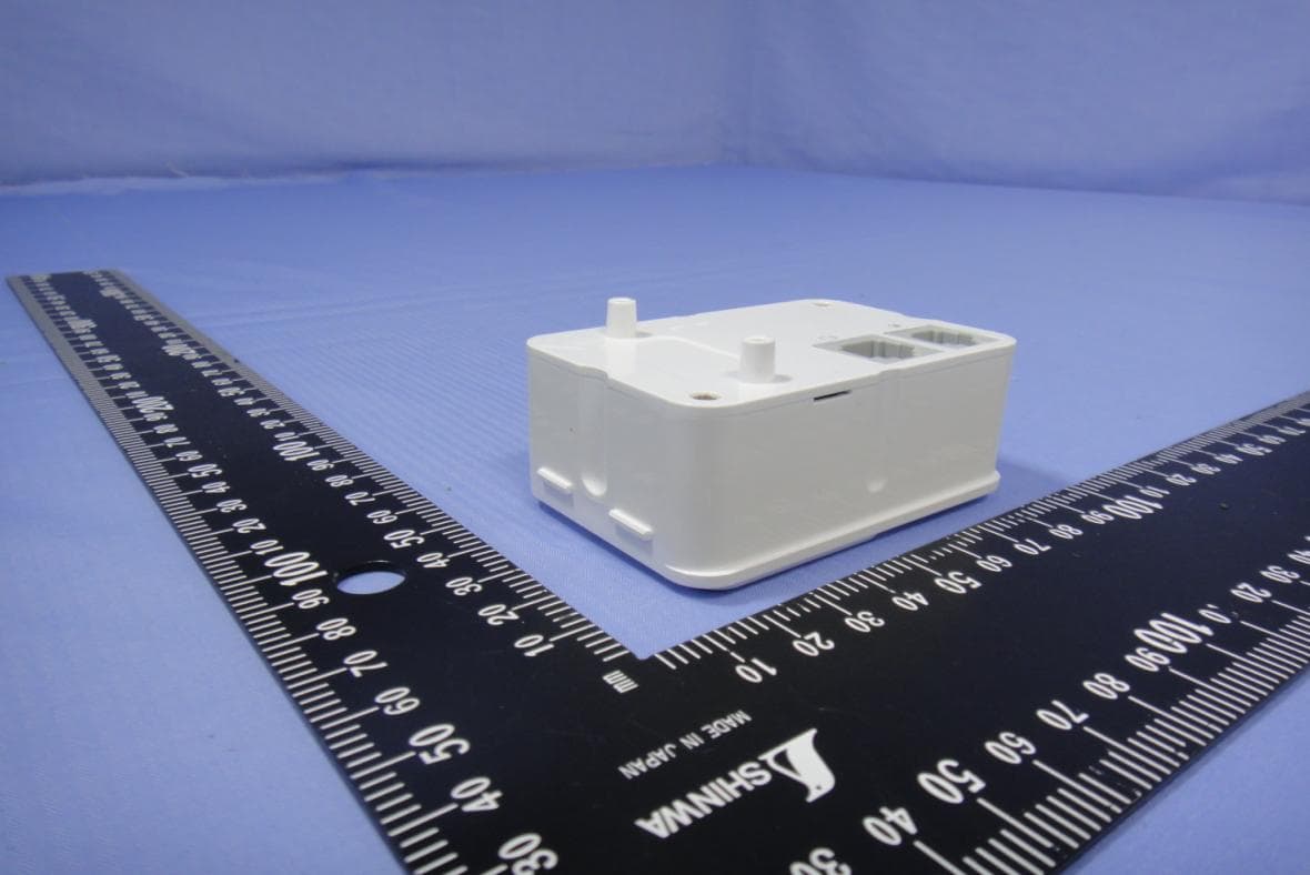
Compliance Certification Services Inc. Report No.: 91124003 Date of Issue: March 3, 2010 Page 1 Rev. 00 EXTERNAL PHOTOGRAPHS OF EUT For Plastics Housing with 14.84dBi Patch Antenna Compliance Certification Services Inc. Report No.: 91124003 Date of Issue: March 3, 2010 Page 2 Rev. 00 Compliance Certification Services Inc. Report No.: 91124003 Date of Issue: March 3, 2010 Page 3 Rev. 00 For Small Aluminum Housing with 14.84dBi Patch Antenna Compliance Certification Services Inc. Report No.: 91124003 Date of Issue: March 3, 2010 Page 4 Rev. 00 For Big Aluminum Housing with 12dBi Patch Antenna Compliance Certification Services Inc. Report No.: 91124003 Date of Issue: March 3, 2010 Page 5 Rev. 00 For Small Aluminum Housing with 12dBi Omni Antenna Compliance Certification Services Inc. Report No.: 91124003 Date of Issue: March 3, 2010 Page 6 Rev. 00 Power Adapter for DSA-15P-24 US 240120 Compliance Certification Services Inc. Report No.: 91124003 Date of Issue: March 3, 2010 Page 7 Rev. 00 Power Adapter for DSA-15P-24 AR 240120 Compliance Certification Services Inc. Report No.: 91124003 Date of Issue: March 3, 2010 Page 8 Rev. 00 Power Adapter for DSA-15P-24 EU 240120 Compliance Certification Services Inc. Report No.: 91124003 Date of Issue: March 3, 2010 Page 9 Rev. 00 PoE for A5-20S48-V Compliance Certification Services Inc. Report No.: 91124003 Date of Issue: March 3, 2010 Page 10 Rev. 00 Compliance Certification Services Inc. Report No.: 91124003 Date of Issue: March 3, 2010 Page 11 Rev. 00 PoE for EBU-101-03 LF Compliance Certification Services Inc. Report No.: 91124003 Date of Issue: March 3, 2010 Page 12 Rev. 00 Compliance Certification Services Inc. Report No.: 91124003 Date of Issue: March 3, 2010 Page 13 Rev. 00 Omni Antenna Compliance Certification Services Inc. Report No.: 91124003 Date of Issue: March 3, 2010 Page 14 Rev. 00
Internal Photos
Compliance Certification Services Inc. Report No.: 91124003 Date of Issue: March 3, 2010 Page 15 Rev. 00 INTERNAL PHOTOGRAPHS OF EUT For Plastics Housing with 14.84dBi Patch Antenna Compliance Certification Services Inc. Report No.: 91124003 Date of Issue: March 3, 2010 Page 16 Rev. 00 Patch Antenna Compliance Certification Services Inc. Report No.: 91124003 Date of Issue: March 3, 2010 Page 17 Rev. 00 Compliance Certification Services Inc. Report No.: 91124003 Date of Issue: March 3, 2010 Page 18 Rev. 00 Compliance Certification Services Inc. Report No.: 91124003 Date of Issue: March 3, 2010 Page 19 Rev. 00 Compliance Certification Services Inc. Report No.: 91124003 Date of Issue: March 3, 2010 Page 20 Rev. 00 Compliance Certification Services Inc. Report No.: 91124003 Date of Issue: March 3, 2010 Page 21 Rev. 00 For Small Aluminum Housing with 14.84dBi Patch Antenna Compliance Certification Services Inc. Report No.: 91124003 Date of Issue: March 3, 2010 Page 22 Rev. 00 Compliance Certification Services Inc. Report No.: 91124003 Date of Issue: March 3, 2010 Page 23 Rev. 00 Compliance Certification Services Inc. Report No.: 91124003 Date of Issue: March 3, 2010 Page 24 Rev. 00 Compliance Certification Services Inc. Report No.: 91124003 Date of Issue: March 3, 2010 Page 25 Rev. 00 Patch Antenna
Internal Photos
Compliance Certification Services Inc. Report No.: 91124003 Date of Issue: March 3, 2010 Page 26 Rev. 00 For Big Aluminum Housing with 12dBi Patch Antenna Compliance Certification Services Inc. Report No.: 91124003 Date of Issue: March 3, 2010 Page 27 Rev. 00 Patch Antenna Compliance Certification Services Inc. Report No.: 91124003 Date of Issue: March 3, 2010 Page 28 Rev. 00 Compliance Certification Services Inc. Report No.: 91124003 Date of Issue: March 3, 2010 Page 29 Rev. 00 Compliance Certification Services Inc. Report No.: 91124003 Date of Issue: March 3, 2010 Page 30 Rev. 00 Compliance Certification Services Inc. Report No.: 91124003…
Text truncated - open the document above for the full version.
Contact Information
Applicant
Spencer Chen
Technical Contact
Compliance Certification Services Inc.Landy Sung
No. 11, Wu-Gong 6th Rd., Wugu Industrial park · Taipei Hsien · Taiwan
Test Firm
Compliance Certification Services Inc.Hank Lee
Technical Specifications
| # | Rule Parts | Frequency Range | Power Output |
|---|---|---|---|
| 3 | 15C | 5.75 GHz - 5.79 GHz | 42.20 mW |
Other Applications from LanReady Technologies Inc.
SCDIW181000001
May 12, 2014802.11n 1x1 In-Wall access Point
Equipment Class
DTS - Digital Transmission System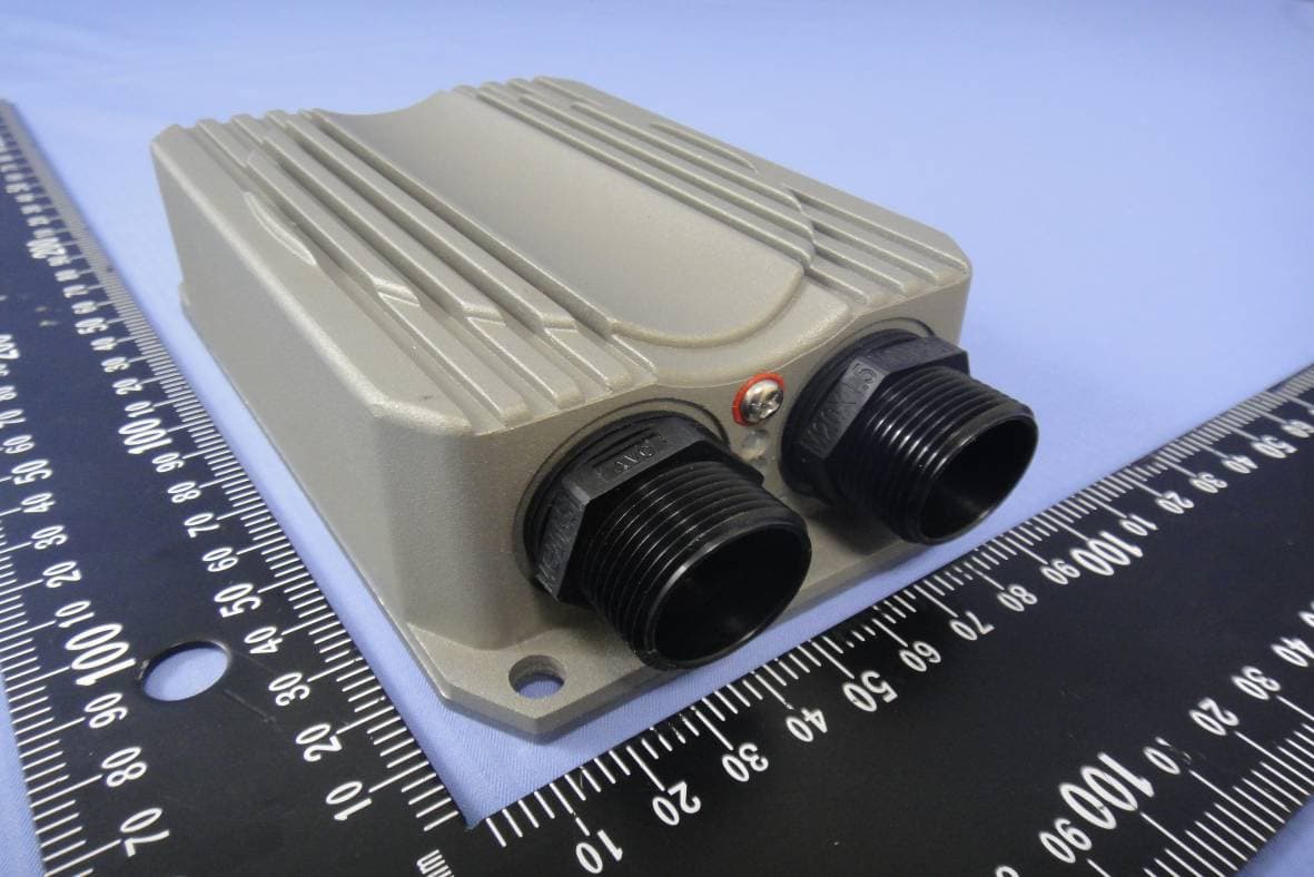
SCDOW161000001
Jan 06, 2014AP Router
Equipment Class
DTS - Digital Transmission System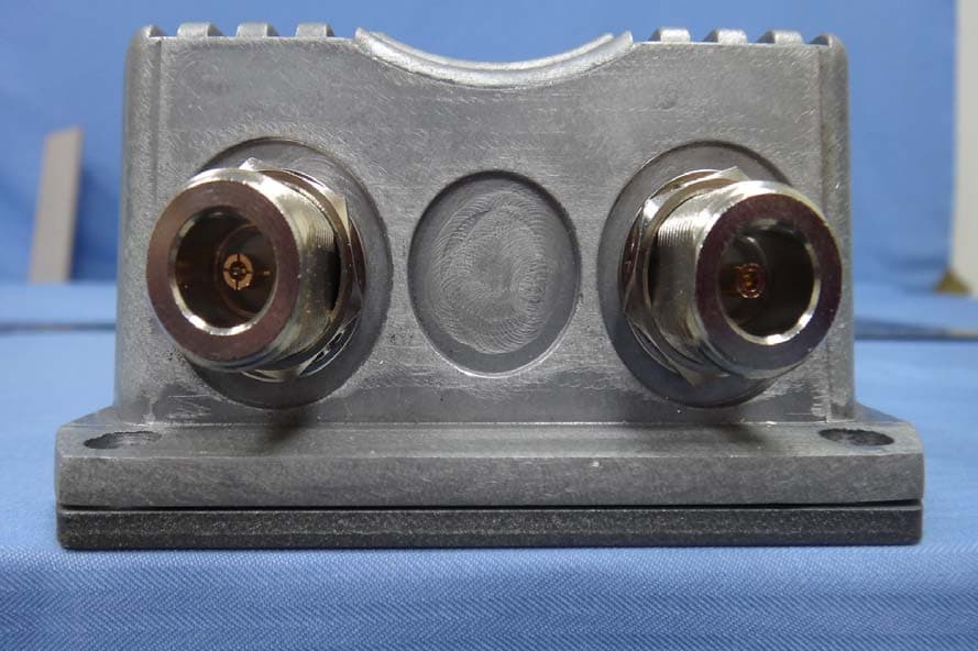
SCDOW141000001
Aug 08, 2013AP Router
Equipment Class
DTS - Digital Transmission System
SCDDS505
Dec 09, 20125-Ports 10/100/1000 Mbps Green Switch
Equipment Class
JBP - Part 15 Class B Computing Device Peripheral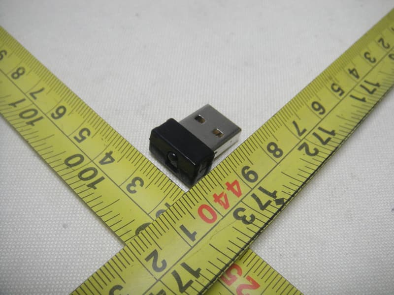
SCD030025
Oct 10, 2011USB Wireless Adapter
Equipment Class
DTS - Digital Transmission System