SRD10040900 MHz ISM BAND TRANSMITTER
TandD Corporation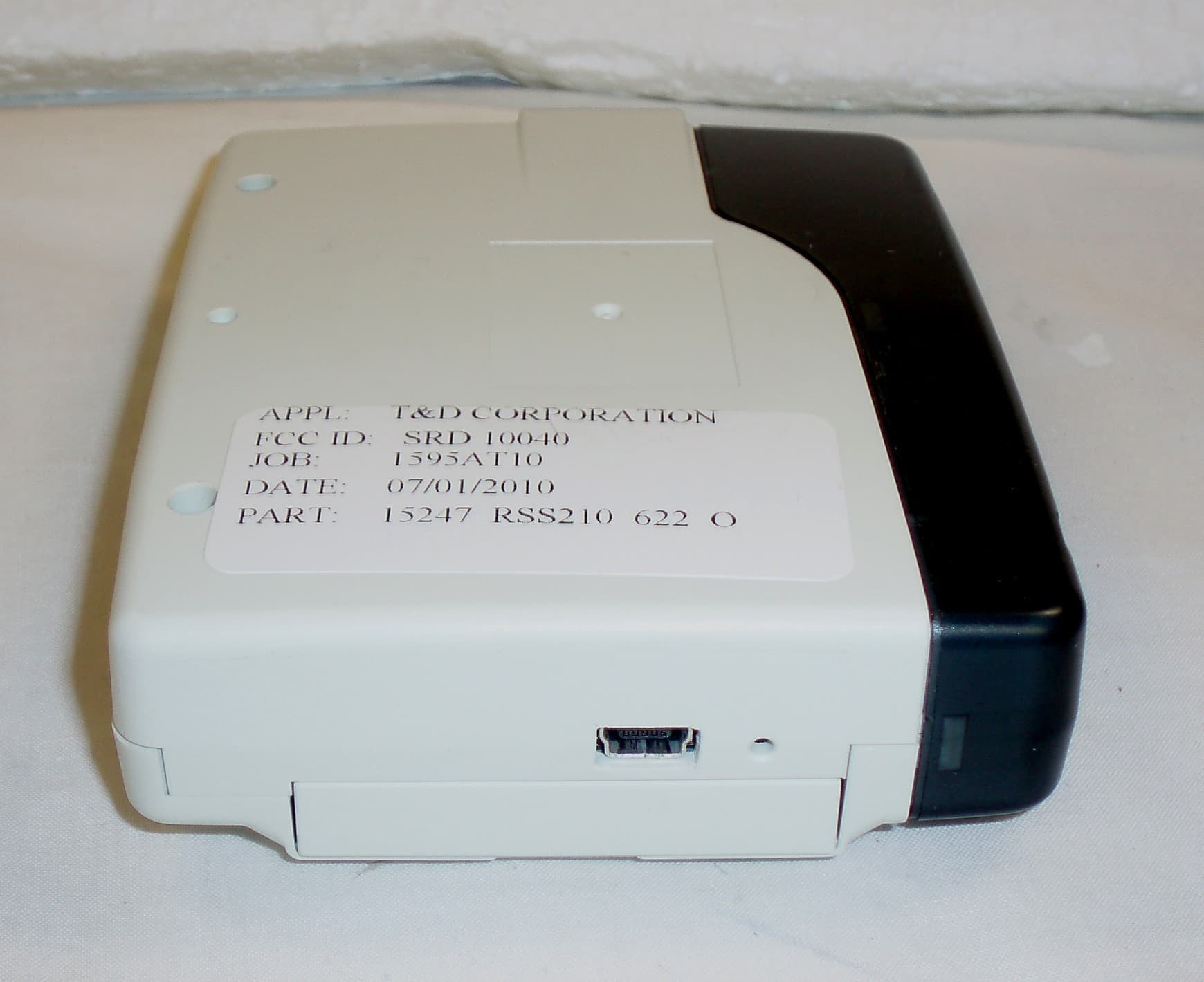
Click to zoom
Application Details
- Equipment Class
- DSS - Part 15 Spread Spectrum Transmitter
- Date of Grant
- Sep 06, 2010
- Application Purpose
- Original Equipment
- Date of Application
- Aug 25, 2010
- Equipment Note
- 900 MHz ISM BAND TRANSMITTER
- Frequency Range
- 902.00000000 - 928.00000000
- Company
- TandD Corporation
- Country
- Japan
Documents & Files
Document Text
Text extracted from the exhibit documents filed with the FCC. Open a document above to read the original.
Users Manual
Network Base Station RTR-500NW RTR-500AW © Copyright T&D Corporation. All rights reserved. 2010.XX 165XXXXxxxx (1st Edition) Introductory Manual Thank you for purchasing our product. This manual explains in brief how to get an RTR-500NW/500AW unit ready for use and how to install the software. Details about how to use the software "RTR-500W for Windows" and its functions can be found in the software "Operation Guide (Help)". For product information or questions contact us at: 817-1 Shimadachi, Matsumoto, Nagano, JAPAN 390-0852 Fax: +81-263-40-3152 E-mail: [email protected] Website http://www.tandd.com/ We have opened an English Website for your convenience. Here you can find information about our company, news, products, upcoming events, software and Introductory Manual downloads, as well as, other support. Please stop by and see what we have to offer. Network Base Station RTR-500NW/500AW Introductory Manual Published by T&D Corporation © Copyright T&D Corporation. All rights reserved. This is printed on recycled paper. Network Base Station RTR-500NW/500AW Warranty RTR-500NW RTR-500AW Customer's name: Address: Phone No.: Dealer's name: Address: Phone No.: Guarantee period: 12 months from date of purchase Date of purchase: Statement of Limited Warranty 1. This product is warranted to be free from defects in materials and workmanship for a period of one (1) year following the date of purchase. Should the product fail to operate per specification in normal use during this period T&D will repair the Unit or provide a replacement free of charge. T&D will not accept returns for any reason other than defects during the warranty period, and will not accept any product that has been misused, dropped, abused or inappropriately used or mistreated at any time. 2. This warranty is strictly limited to repair or replacement-in-kind for defective product. T&D makes no other warranty, either express or implied, and will not accept liability beyond the remedies stated herein. Specifically, T&D will not accept liability for direct, indirect, special, consequential or incidental damages arising from the use of this product. 3. Customers wishing to submit a defective product for repair or replacement during the warranty period should first contact the dealer from whom it was originally purchased. After receiving a return authorization the defective product should then be packaged along with a description of the difficulties being experienced, proof of purchase and all included accessories and materials, and return it to the dealer. In the event of difficulty contacting the original dealer, customers should contact the nearest authorized T&D sales representative. A list of these can be found on the company's web site, www.tandd.com, or it can be obtained by contacting T&D directly. 4. This limited warranty statement gives the customer specific legal rights. The customer may also have other rights which vary from state to state in the United States, from province to province in Canada, and from country to country elsewhere in the world. To the extent this limited warranty statement is inconsistent with local law, this statement shall be deemed modified to be consistent with such local law. 5. For further information relating to product repair or replacement, or for other service questions after the termination of the warranty period, customers should contact their local authorized T&D sales representative. Table of Contents Introduction Notices --------------------------------------------------------2 Software User Agreement ------------------------------- 3 Safety Precautions and Instructions -----------4 Explanation of Symbols ----------------------------------4 Features of RTR-500NW/500AW --------------10 Make Registration Changes via Network ----------11 Monitoring Current Readings and Viewing Recorded Data via Web Browser ---------------------------------11 What are "Base Units", "Remote Units" and "Repeaters"? ----------------------------------------12 Base Unit: RTR-500NW / RTR-500AW ------------12 Remote Unit: RTR-501 / RTR-502 / RTR-503 ---- 12 Repeater: RTR-500 -------------------------------------- 12 About Registration --------------------------------------- 13 Basic Procedure Flow ----------------------------14 Getting Ready Package Contents --------------------------------16 Connect the Antenna ------------------------------------16 Appearance Diagram and Part Names -------17 Installing the Software ---------------------------- 19 Before Installing the Software -------------------------19 Procedure for Installing the Software --------------- 20 Installing the USB Device Driver ---------------23 Procedure for Installing the USB Device Driver --24 Checking the USB Device Driver --------------------- 25 Re-installing the USB Device Driver ----------------- 27 Registering Device and Making Settings About Applications and the Operation Guide 32 How to Open ----------------------------------------------32 Registering Devices and Making Settings ---33 1. Base Unit Settings -----------------------------------33 2. Remote Unit Registration -------------------------- 33 3. Base Unit Operational Settings ------------------ 34 4. Repeater Registration (Only if necessary) ------ 34 Notes about Operation Before Using ---------------------------------------36 Connecting the AC Adaptor ---------------------------36 LED Lamps before Starting Operation -------------- 36 Useful Features and Functions -----------------37 Changing Settings during Operation ---------------37 Registering Remote Units via an RTR-500 ------- 37 LED Lamp Display ---------------------------------38 External Contact Output / Input Terminals --- 39 What is the External Contact Output? -------------39 What is the External Contact Input? ---------------- 39 Installing and Removing Wires ----------------------- 39 Uninstalling the Software -----------------------40 Product Specifications ---------------------------- 42 RTR-500NW/500AW ---------…
Text truncated - open the document above for the full version.
Cover Letter(s)
TIMCO ENGINEERING INC. 849 NW State Road 45 Newberry, Florida 32669 http://www.timcoengr.com 888.472.2424 F 352.472.2030 email: [email protected] TCB FCC Approvals FCB Industry Canada Approval NB Notified Body for Europe September 7, 2010 FCC [email protected] Subject: T&D CORPORATION - FCC ID: SRD10040 To whom it may concern: The exhibit named “Circuit Description 2“ was incorrectly uploaded under Internal Photos. This exhibit has been superseded and uploaded correctly. Please feel free to contact us if you have any questions. Thank you, Gretchen Greene Timco Engineering Inc.
External Photos
T&D CORPORATION FCC ID: SRD10040 EXTERNAL PHOTOS
ID Label/Location Info
29.6 22.6 4-R0.2 シリアルNo. ・シリアルNo.詳細 32A 00001 00001~1FFFF(16進法) 固定 坂野 162-0706-1010 RTR-500AW シリアルシール ・材質:PET 50μ ベース色:白 ・文字色:黒 ・表面はラミネート処理 ・版下No.852-0706-1060 上記 坂野 10.05.17 瀬木 設計 製図 検図 承認 内 容 年 月 日 担当 株式会社 ティアンドデイ 材料 処理 品名 製品コード 0 0.5 0.5 6 6 30 30 120 120 350 350 1000 ±0.05 ±0.1 ±0.2 ±0.3 ±0.5 ±0.8 1 2 3 差 公 度 尺 位 単 2:1 Doc.No.851-0706-0010 mm
ID Label/Location Info
10 06 03 坂野 詳細は版下による DocNo:85207061000 尺度:1:1 図名:RTR-500AW 外観イメージ 日付:2010/06/03 作成:坂野 T&D Corporation
Internal Photos
T&D CORPORATION FCC ID: SRD10040 INTERNAL PHOTOS
Test Report
FCC PART 15.247 AN IC RSS-210 TEST REPORT DIGITAL SPREAD SPECTRUM Applicant T&D CORPORATION Address 817-1 SHIMADACHI MATSUMOTO 390-0852 JAPAN FCC ID SRD10040 IC 5558A-10040 Model Number RTR-500AW Product Description 900 MHz ISM BAND TRANSMITTER Date Sample Received 7/1/2010 Date Tested 7/27/2010 Tested By Joe Scoglio Approved By Mario R. de Aranzeta Report Number 1595AT10TestReport.doc Test Results PASS FAIL THE ATTACHED REPORT SHALL NOT BE REPRODUCED EXCEPT IN FULL WITHOUT THE WRITTEN APPROVAL OF TIMCO ENGINEERING, INC. 849 NW State Road 45 Newberry, FL 32669 USA Ph: 888.472.2424 or 352.472.5500 Fax: 352.472.2030 Email: [email protected] Website: www.timcoengr.com Testing Certificate # 0955-01 APPLICANT: T&D CORPORATION FCC ID: SRD10040 IC: 5558A-10040 REPORT: Z:\T\T&D CORP_SRD\1595AT10\1595AT10TestReport.doc Page 2 of 18 TABLE OF CONTENT GENERAL REMARKS ............................................................................................................................... 3 GENERAL INFORMATION ........................................................................................................................ 4 EMC EQUIPMENT LIST............................................................................................................................ 5 TEST PROCEDURES ................................................................................................................................ 6 RADIATION INTERFERENCE ................................................................................................................... 7 POWER LINE CONDUCTED INTERFERENCE ........................................................................................ 10 OCCUPIED BANDWIDTH ....................................................................................................................... 12 POWER OUTPUT .................................................................................................................................... 13 SPURIOUS EMISSIONS AT ANTENNA TERMINALS ............................................................................... 14 RADIATED SPURIOUS EMISSIONS INTO ADJACENT RESTRICTED BAND .......................................... 15 POWER SPECTRAL DENSITY ................................................................................................................ 18 APPLICANT: T&D CORPORATION FCC ID: SRD10040 IC: 5558A-10040 REPORT: Z:\T\T&D CORP_SRD\1595AT10\1595AT10TestReport.doc Page 3 of 18 GENERAL REMARKS The attached report shall not be reproduced except in full without the written permission of Timco Engineering Inc. The test results relate only to the items tested. Summary The device under test does: fulfill the general approval requirements as identified in this test report not fulfill the general approval requirements as identified in this test report Attestations This equipment has been tested in accordance with the standards identified in this test report. To the best of my knowledge and belief, these tests were performed using the measurement procedures described in this report. All instrumentation and accessories used to test products for compliance to the indicated standards are calibrated regularly in accordance with ISO 17025 requirements. Testing Certificate # 0955-01 I attest that the necessary measurements were made, under my supervision, at: Timco Engineering Inc. 849 NW State Road 45 Newberry, Fl 32669 Authorized Signatory Name: Mario de Aranzeta C.E.T. Compliance Engineer/ Lab. Supervisor Date: 7/27/2010 APPLICANT: T&D CORPORATION FCC ID: SRD10040 IC: 5558A-10040 REPORT: Z:\T\T&D CORP_SRD\1595AT10\1595AT10TestReport.doc Page 4 of 18 GENERAL INFORMATION DUT Specification Applicable Standard Part 15.247 DUT Description 900 MHz ISM BAND TRANSMITTER FCC ID SRD10040 IC 5558A-10040 Operating Frequency TX/RX: 902 to 928 MHz DUT Power Source 110–120Vac/50– 60Hz DC Power Battery Operated Exclusively Test Item Prototype Pre-Production Production Type of Equipment Fixed Mobile Portable Antenna Connector Reverse SMA Antenna Dipole Test Facility Timco Engineering Inc. located at 849 NW State Road 45 Newberry, FL 32669 USA. Test Conditions Temperature: 26ºC Relative humidity: 50% Test Exercise The DUT was placed in continuous transmit mode of operation. Test Supporting Equipment Supporting Device Manufacturer Model / FCC ID Serial Number N/A APPLICANT: T&D CORPORATION FCC ID: SRD10040 IC: 5558A-10040 REPORT: Z:\T\T&D CORP_SRD\1595AT10\1595AT10TestReport.doc Page 5 of 18 EMC EQUIPMENT LIST Device Manufacturer Model Serial Number Cal/Char Date Due Date 3-Meter Semi- Anechoic Chamber Panashield N/A N/A Listed 3/10/10 3/10/12 AC Voltmeter HP 400FL 2213A14499 CAL 3/23/09 3/23/11 Antenna: Dipole Kit Electro- Metrics TDA-30/1-4 153 CHAR 6/10/09 6/10/11 Frequency Counter HP 5385A 3242A07460 CAL 5/26/09 5/26/11 Hygro- Thermometer Extech 445703 0602 CAL 1/30/09 1/30/11 Modulation Analyzer HP 8901A 3435A06868 CAL 5/26/09 5/26/11 Digital Multimeter Fluke FLUKE-77-3 79510405 CAL 5/18/09 5/18/11 Analyzer Tan Tower Preamplifier HP 8449B-H02 3008A00372 CAL 11/21/09 11/21/11 Analyzer Tan Tower Quasi- Peak Adapter HP 85650A 3303A01690 CAL 11/22/09 11/22/11 Analyzer Tan Tower RF Preselector HP 85685A 3221A01400 CAL 11/21/09 11/21/11 Analyzer Tan Tower Spectrum Analyzer HP 8566B Opt 462 3138A07786 3144A20661 CAL 11/24/09 11/24/11 Temperature Chamber Tenney Engineering TTRC 11717-7 CHAR 4/25/10 4/25/12 APPLICANT: T&D CORPORATION FCC ID: SRD10040 IC: 5558A-10040 REPORT: Z:\T\T&D CORP_SRD\1595AT10\1595AT10TestReport.doc Page 6 of 18 TEST PROCEDURES Radiation Interference: ANSI C63.4-2003 using a spectrum analyzer, a preselector, a quasi-peak adapter, and an appropriate antenna. The analyzer was calibrated in dB above a microvolt at the output of the antenna. The resolution bandwidth was 100 kHz with an appropriate sweep speed and the video bandwidth was 300 kHz up to 1 GHz and 1 MHz with a video BW of 3 MHz above 1 GHz. When an emission was found, the…
Text truncated - open the document above for the full version.
Contact Information
Applicant
Akemi Oana(Sales Department)
Test Firm
Timco Engineering, Inc.Bruno Clavier
Technical Specifications
| # | Rule Parts | Frequency Range | Power Output |
|---|---|---|---|
| 1 | 15C | 902 MHz - 928 MHz | 5.00 mW |
Other Applications from TandD Corporation
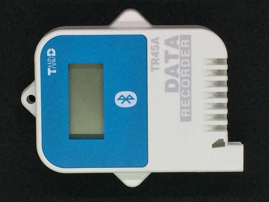
SRD50150
Sep 26, 2024Data Logger
Equipment Class
DTS - Digital Transmission System
SRD50140
Apr 08, 2023Data Logger
Equipment Class
DTS - Digital Transmission System
SRD50110
Jul 11, 2021Data Logger
Equipment Class
DTS - Digital Transmission System
SRD50100
Dec 02, 2020Data Logger Remote Unit
Equipment Class
DTS - Digital Transmission System
SRD10100
Dec 02, 2020Data Logger Base Unit
Equipment Class
DTS - Digital Transmission System