SRD10060Wireless Dongle
TandD Corporation
Click to zoom
Application Details
- Equipment Class
- JBP - Part 15 Class B Computing Device Peripheral
- Date of Grant
- May 22, 2011
- Application Purpose
- Original Equipment
- Date of Application
- May 22, 2011
- Equipment Note
- Wireless Dongle
- Company
- TandD Corporation
- Country
- Japan
Documents & Files
Document Text
Text extracted from the exhibit documents filed with the FCC. Open a document above to read the original.
Users Manual
Cautions about using the Wireless Dongle(RTR-300) The following items should be strictly obeyed for the safe usage of this product, and for protecting yourself and other people from bodily harm and/or damage to property. Before using this product, please carefully read, understand, and follow the safety rules and precautions outlined below. Explanation of Warning Symbols Danger These entries denote the safety rules and precautions which, if failed to be followed, can cause serious physical damage or death. Caution These entries denote the safety rules and precautions which, if failed to be followed, can cause physical injury or damage to persons or things. Explanation of Picture Symbols Denotes an important warning or actions. Denotes a forbidden action. Denotes an action that must be taken. Danger Do not use an AC adaptor other than the one that is specified by T&D Corporation. Do not short out, take apart, modify, deform, solder, or try to repair this product. Do not store, leave, or use the product in any place subject to high temperatures such as direct sunlight or near heating equipment, or to extremely low temperatures. Make sure not to get it wet. If it does get wet, immediately stop using. Do not use or store in humid places such as a bathroom. Do not use in or near fire, nor directly put into cooking equipment such as a microwave oven or a high pressure cooker. Caution This is a precision piece of equipment. Do not expose to strong impact or throw it. Before inserting or removing the Product, please first touch metal around you (steel desk, door knob) to clear static electricity. Set and store out of the reach of infants. If and when a child is to use the product, make sure they are given proper instructions on how to use it. Do not touch with wet hands. If the product is not to be used for a long period of time, make sure to disconnect it from the AC adaptor and PC. Do not connect to a PC using a USB hub. This product is not for saving data. Notices about this Document and Disclaimers -Due to continual improvements specifications, design and other contents outlined in the document are subject to change without notice. -Please follow the safety precautions outlined in this document carefully. -T&D Corporation accepts no responsibility for any damages which occurred due to natural disasters and factors which are not the responsibility of T&D, including fire, acts by the third party, other accidents, your willful or negligent misuse, abuse, mishandling or other use under abnormal conditions. -We cannot guarantee nor are we responsible for safety if this product is used in any manner other than was intended. We accept no responsibility for any damage or loss of income caused by the use of our product. -We are not responsible for any malfunction or trouble caused by the use of our product or by any problem caused by the use of measurement results of our product. Please be fully aware of this before using our product. -We accept no responsibility for any damages arising from the use of this product in combination with any and all types of connective devices not related to T&D.
External Photos
ATTACHMENT A1 to File No.: T35019-00 mikes-testingpartners gmbh Ohmstrasse 2-4 D-94342 Strasskirchen Tel:+49-9424-9481-0 Fax:+49-9424-9481-240 Photo documentation of the EUT Model: RTR-300 External Views: ATTACHMENT A1 to File No.: T35019-00 mikes-testingpartners gmbh Ohmstrasse 2-4 D-94342 Strasskirchen Tel:+49-9424-9481-0 Fax:+49-9424-9481-240 External Views:
ID Label/Location Info
9.4 ケース上下勘合時に接着。 19.5 79.5 認証シリアルシール 設計 製図 検図 承認 内 容 年 月 日 担当 株式会社 ティアンドデイ 材料 処理 品名 製品コード 0 0.5 0.5 6 6 30 30 120 120 350 350 1000 ±0.05 ±0.1 ±0.5 ±0.8 1 2 3 ±0.2 ±0.3 差 公 度 尺 量 数 Doc.No.851-0454-7000 1:1 福田 09/07/28 0454 RTR-300 外観図
Internal Photos
ATTACHMENT A1 to File No.: T35019-00 mikes-testingpartners gmbh Ohmstrasse 2-4 D-94342 Strasskirchen Tel:+49-9424-9481-0 Fax:+49-9424-9481-240 Internal view – Rear view of PCB: ATTACHMENT A1 to File No.: T35019-00 mikes-testingpartners gmbh Ohmstrasse 2-4 D-94342 Strasskirchen Tel:+49-9424-9481-0 Fax:+49-9424-9481-240 Internal view – Front view of PCB:
Test Report
mikes-testingpartners gmbh File No. T35019-00-08HU, page 1 of 16 Ohmstrasse 2-4 x 94342 Strasskirchen Tel.:+49(0)9424-94810 x Fax:+49(0)9424-9481240 Rev. No. 1.2, 9.9.2010 EMI − T E S T R E P O R T - FCC Part 15B - Test Report No. : T35019-00-08HU 18. May 2011 ______________________________________________________________________________________________ Date of issue Type / Model Name : RTR-300 Product Description : Wireless Dongle Applicant : T&D CORPORATION Address : 817-1 Shimadachi Matsumoto City NAGANO 390-0852 JAPAN Manufacturer : T&D CORPORATION Address : 817-1 Shimadachi Matsumoto City NAGANO 390-0852 JAPAN Licence holder : T&D CORPORATION Address : 817-1 Shimadachi Matsumoto City NAGANO 390-0852 JAPAN Test Result according to the standards listed in clause 1 test standards: POSITIVE The test report merely corresponds to the test sample. It is not permitted to copy extracts of these test results without the written permission of the test laboratory. mikes-testingpartners gmbh File No. T35019-00-08HU, page 2 of 16 Ohmstrasse 2-4 x 94342 Strasskirchen Tel.:+49(0)9424-94810 x Fax:+49(0)9424-9481240 Rev. No. 1.2, 9.9.2010 Contents 1 TEST STANDARDS 3 2 SUMMARY 4 3 EQUIPMENT UNDER TEST 5 3.1 Photo documentation of the EUT – Detailed photos see Attachment A1 5 3.2 Power supply system utilised 5 3.3 Short description of the equipment under test (EUT) 5 4 TEST ENVIRONMENT 7 4.1 Address of the test laboratory 7 4.2 Environmental conditions 7 4.3 Statement of the measurement uncertainty 7 4.4 Measurement Protocol for FCC, VCCI and AUSTEL 8 5 TEST CONDITIONS AND RESULTS 9 5.1 Conducted emissions 9 5.2 Radiated emissions 13 6 USED TEST EQUIPMENT AND ACCESSORIES 16 mikes-testingpartners gmbh File No. T35019-00-08HU, page 3 of 16 Ohmstrasse 2-4 x 94342 Strasskirchen Tel.:+49(0)9424-94810 x Fax:+49(0)9424-9481240 Rev. No. 1.2, 9.9.2010 1 TEST STANDARDS The tests were performed according to following standards: FCC Rules and Regulations Part 15 Subpart A - General (October, 2010) Part 15, Subpart A, Section 15.31 Measurement standards Part 15, Subpart A, Section 15.33 Frequency range of radiated measurements Part 15, Subpart A, Section 15.35 Measurement detector functions and bandwidths FCC Rules and Regulations Part 15 Subpart B - Unintentional Radiators (October, 2010) Part 15, Subpart B, Section 15.107 AC Line conducted emissions, Class B Part 15, Subpart B, Section 15.109 Radiated emissions, general requirements, Class B ANSI C63.4: 2003 Methods of Measurement of Radio-Noise Emissions from Low- Voltage Electrical and Electronic Equipment in the Range of 9 kHz to 40 GHz. CISPR 16-4-2: 2003 Uncertainty in EMC measurement CISPR 22: 2005 Information technology equipment EN 55022: 2006 mikes-testingpartners gmbh File No. T35019-00-08HU, page 4 of 16 Ohmstrasse 2-4 x 94342 Strasskirchen Tel.:+49(0)9424-94810 x Fax:+49(0)9424-9481240 Rev. No. 1.2, 9.9.2010 2 SUMMARY GENERAL REMARKS: The EuT is capable to exchange data with a PC via USB port. The EuT can also connected to an AC Adapter (sold separately) and used as a Repeater. This test report describes the radiated disturbance by the data transfer via USB port and conducted disturbance produced by using an AC Adapter. The measurement has been performed in Standby (Dongle Open). The EuT is declared as Class B digital device. FINAL ASSESSMENT: The equipment under test fulfills the EMI requirements cited in clause 1 test standards. Date of receipt of test sample : acc. to storage records Testing commenced on : 07. March 2011 Testing concluded on : 06. April 2011 Checked by: Tested by: Harald Buchwald Dipl. Ing.(FH) Manager: EMC Markus Huber mikes-testingpartners gmbh File No. T35019-00-08HU, page 5 of 16 Ohmstrasse 2-4 x 94342 Strasskirchen Tel.:+49(0)9424-94810 x Fax:+49(0)9424-9481240 Rev. No. 1.2, 9.9.2010 3 EQUIPMENT UNDER TEST 3.1 Photo documentation of the EUT – Detailed photos see Attachment A1 3.2 Power supply system utilised Power supply voltage : 5.0 V / DC (USB power) 3.3 Short description of the equipment under test (EUT) The EuT is a wireless dongle. The RTR-300 allows wireless communication between RTR-322 units and a PC. Number of tested samples: 1 Serial number: see Photo documentation of the EuT / Equipment Under Test The equipment under test was operated during the measurement under the following conditions: - Standby (Dongle Open) - - EUT configuration: (The CDF filled by the applicant can be viewed at the test laboratory.) The following peripheral devices and interface cables were connected during the measurements: - Test Software Model : Supplied by manufacturer T&D - Laptop Model : Fa. mikes testingpartners gmbh - Model : - Model : - Model : - Model : mikes-testingpartners gmbh File No. T35019-00-08HU, page 6 of 16 Ohmstrasse 2-4 x 94342 Strasskirchen Tel.:+49(0)9424-94810 x Fax:+49(0)9424-9481240 Rev. No. 1.2, 9.9.2010 mikes-testingpartners gmbh File No. T35019-00-08HU, page 7 of 16 Ohmstrasse 2-4 x 94342 Strasskirchen Tel.:+49(0)9424-94810 x Fax:+49(0)9424-9481240 Rev. No. 1.2, 9.9.2010 4 TEST ENVIRONMENT 4.1 Address of the test laboratory mikes-testingpartners gmbh Ohmstrasse 2-4 94342 Strasskirchen Germany 4.2 Environmental conditions During the measurement the environmental conditions were within the listed ranges: Temperature: 15-35 ° C Humidity: 30-60 % Atmospheric pressure: 86-106 kPa 4.3 Statement of the measurement uncertainty The data and results referenced in this document are true and accurate. The reader may notice that tolerances within the calibration of the equipment and facilities may cause additional uncertainty. The measurement uncertainty is calculated for all measurements listed in this test report acc. to CISPR 16-4-2 „Uncertainties, statistics and limit modelling – Uncertainty in EMC measurement“ and documented in the mikes-testingpartners gmbh quality system acc. to DIN EN ISO/IEC 17025. For all measurements shown in this report, the measurement uncertainty of the test laboratory, mikes-testingpartners gmb…
Text truncated - open the document above for the full version.
Test Setup Photos
FCC ID:SRD10060 mikes-testingpartners gmbh File No. T35019-00-04HU, page 9 of 46 Ohmstrasse 2-4 x 94342 STRASSKIRCHEN x GERMANY Tel.:+49(0)9424-94810 xFax: ++49(0)9424-9481240 Rev. No. 1.2, 9.9.2010 5 TEST CONDITIONS AND RESULTS 5.1 Conducted emissions For test instruments and accessories used see section 6 Part A 4. 5.1.1 Description of the test location Test location: Shielded Room S2 5.1.2 Photo documentation of the test set-up 5.1.3 Applicable standard According to FCC Part 15, Section 15.207(a): Except as shown in paragraphs (b) and (c) of this Section, for an intentional radiator that is designed to be connected to the public utility (AC) power line, the radio frequency voltage that is conducted back onto the AC power line on any frequency or frequencies within the band 150 kHz to 30 MHz shall not exceed the given limits. 5.1.4 Description of Measurement The measurements are performed following the procedures set out in ANSI C63.4 described under item 4.4.3. If the minimum limit margin appears to be less than 20 dB with a peak mode measurement, the emissions are remeasured using a tuned receiver with quasi-peak and average detection and recorded on the data sheets. FCC ID:SRD10060 mikes-testingpartners gmbh File No. T35019-00-04HU, page 23 of 46 Ohmstrasse 2-4 x 94342 STRASSKIRCHEN x GERMANY Tel.:+49(0)9424-94810 xFax: ++49(0)9424-9481240 Rev. No. 1.2, 9.9.2010 5.4 Spurious emissions conducted For test instruments and accessories used see section 6 Part SEC1, SEC2 and SEC3. 5.4.1 Description of the test location Test location: Shielded Room S4 5.4.2 Photo documentation of the test set-up 5.4.3 Applicable standard According to FCC Part 15C, Section 15.247(d): In any 100 kHz bandwidth outside the frequency band 902 to 928 MHz, the digitally modulated radio frequency power that is produced by the intentional radiator shall be at least 20 dB below that in the 100 kHz bandwidth within the band that contains the highest level of the desired power, based on either an RF conducted or an radiated measurement. Attenuation below the general limits specified in Section 15.209(a) is not required. In addition, radiated emissions which fall in the restricted bands, as defined in Section 15.205(a), must also comply with the radiated emission limit specified in Section 15.209(a). 5.4.4 Description of measurement A spectrum analyzer is connected to the output of the transmitter while EUT was operating in transmit mode at the assigned frequency. FCC ID:SRD10060 mikes-testingpartners gmbh File No. T35019-00-04HU, page 32 of 46 Ohmstrasse 2-4 x 94342 STRASSKIRCHEN x GERMANY Tel.:+49(0)9424-94810 xFax: ++49(0)9424-9481240 Rev. No. 1.2, 9.9.2010 5.5 Spurious emissions For test instruments and accessories used see section 6 Part SER 1, SER 2, SER 3. 5.5.1 Description of the test location Test location: OATS1 Test distance: 3 metres Test location: Anechoic Chamber A2 Test distance: 3 metres 5.5.2 Photo documentation of the test set-up FCC ID:SRD10060 mikes-testingpartners gmbh File No. T35019-00-04HU, page 33 of 46 Ohmstrasse 2-4 x 94342 STRASSKIRCHEN x GERMANY Tel.:+49(0)9424-94810 xFax: ++49(0)9424-9481240 Rev. No. 1.2, 9.9.2010 5.5.3 Applicable standard According to FCC Part 15, Section 15.247(d): In any 100 kHz bandwidth outside the frequency bands 2400 – 2483.50 MHz and 5725 – 5850 MHz, the digitally modulated radio frequency power that is produced by the intentional radiator shall be at least 20 dB below that in the 100 kHz bandwidth within the band that contains the highest level of the desired power, based on either an RF conducted or an radiated measurement. Attenuation below the general limits specified in Section 15.209(a) is not required. In addition, radiated emissions which fall in the restricted bands, as defined in Section 15.205(a), must also comply with the radiated emission limit specified in Section 15.209(a) (see Section 15.205(c)). 5.5.4 Description of Measurement The radiated power of the spurious emission from the EUT is measured in a test setup following the procedures set out in ANSI C63.4. If the emission level of the EUT in peak mode complies with the average limit is 20 dB lower, then testing will be stopped and peak values of the EUT will be reported, otherwise the emission will be measured in average mode again and reported. 5.5.4.1 Radiated emission test f < 1 GHz In the frequency range from 9 kHz to 30 MHz no emissions from the EuT could be measured. In the frequency range from 30 MHz up to 1 GHz no emissions from the EuT could be measured.
Contact Information
Applicant
Akemi Oana(Sales Department)
Test Firm
CSA Group Bayern GmbHThomas Weise
Technical Specifications
| # | Rule Parts | Frequency Range | Power Output |
|---|---|---|---|
| 1 | 15B | - | - |
Other Applications from TandD Corporation
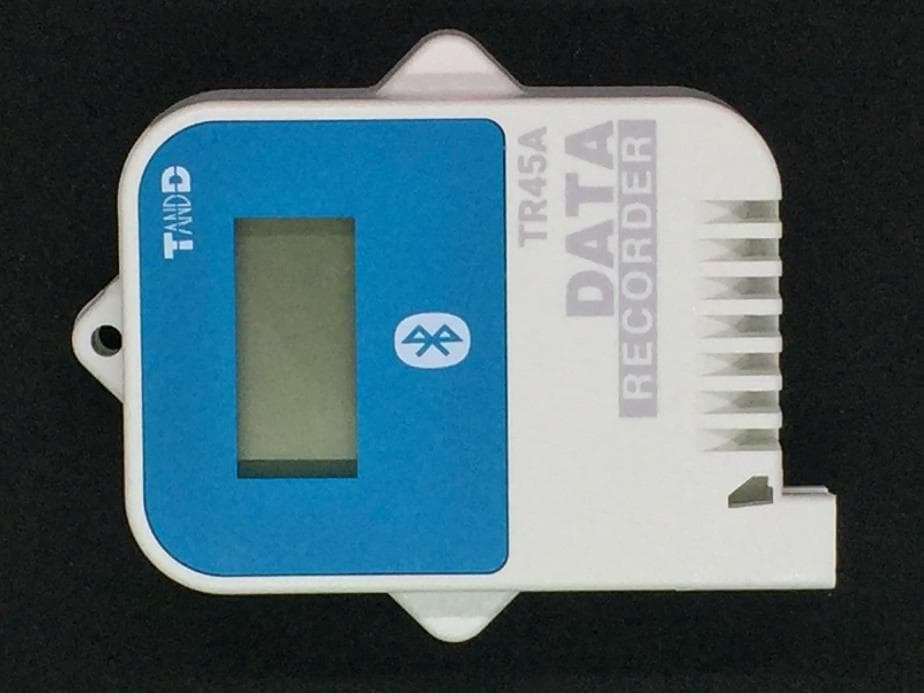
SRD50150
Sep 26, 2024Data Logger
Equipment Class
DTS - Digital Transmission System
SRD50140
Apr 08, 2023Data Logger
Equipment Class
DTS - Digital Transmission System
SRD50110
Jul 11, 2021Data Logger
Equipment Class
DTS - Digital Transmission System
SRD50100
Dec 02, 2020Data Logger Remote Unit
Equipment Class
DTS - Digital Transmission System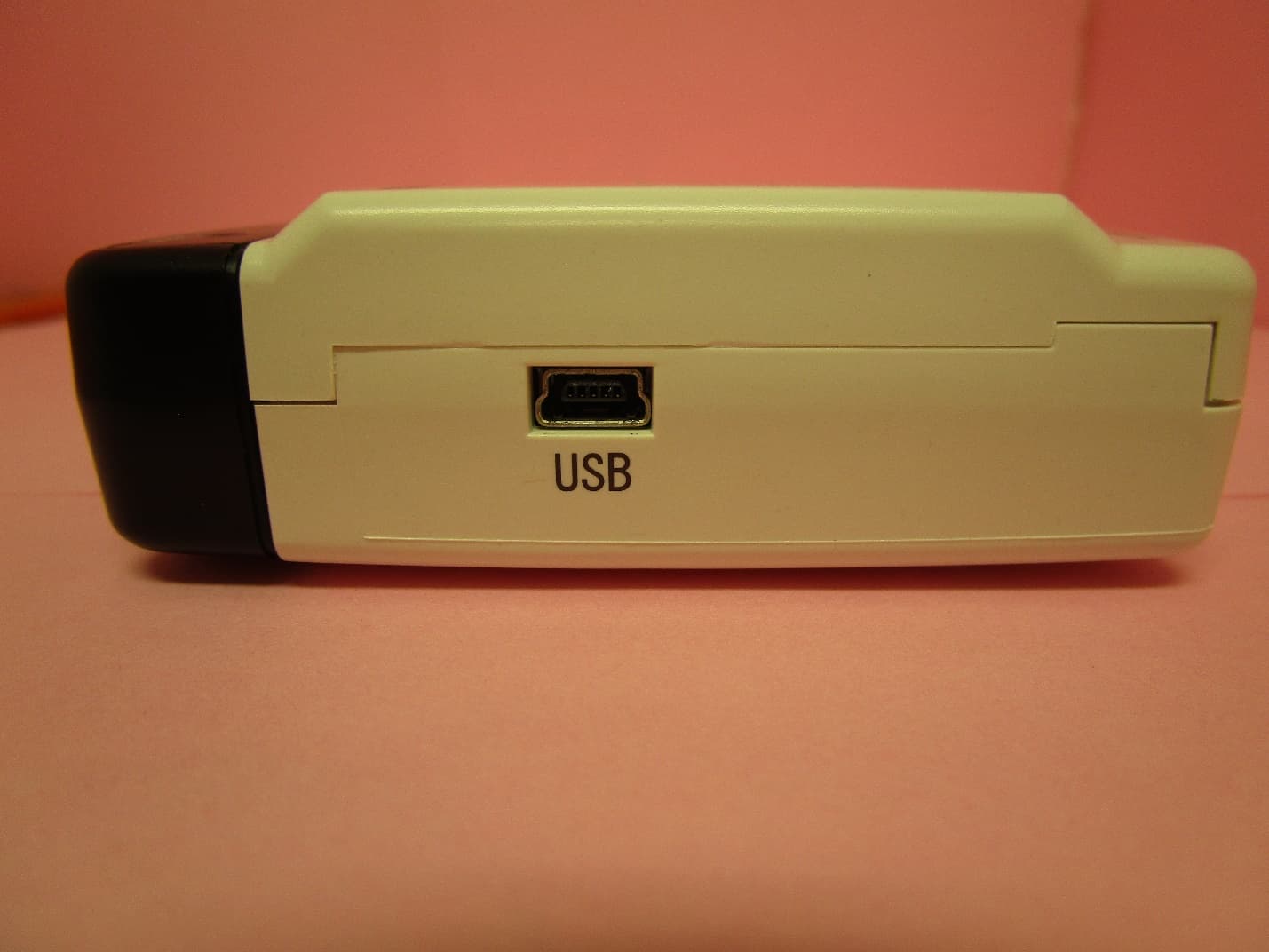
SRD10100
Dec 02, 2020Data Logger Base Unit
Equipment Class
DTS - Digital Transmission System