SRD50020WIRELESS DATA RECORDER
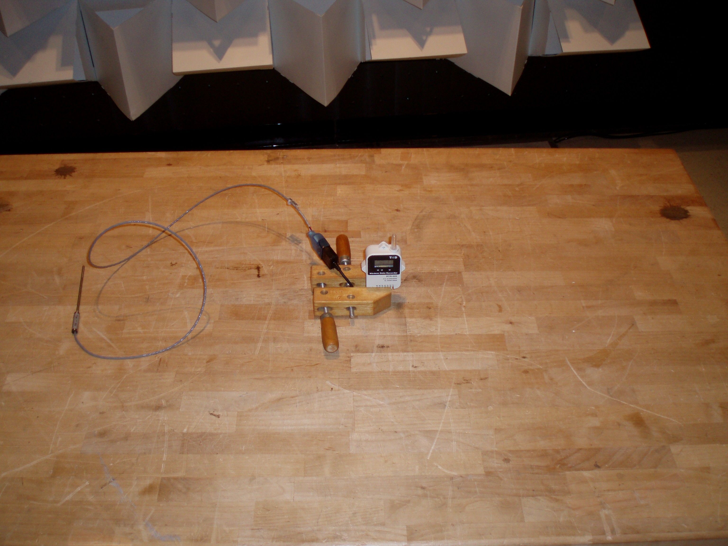
TandD Corporation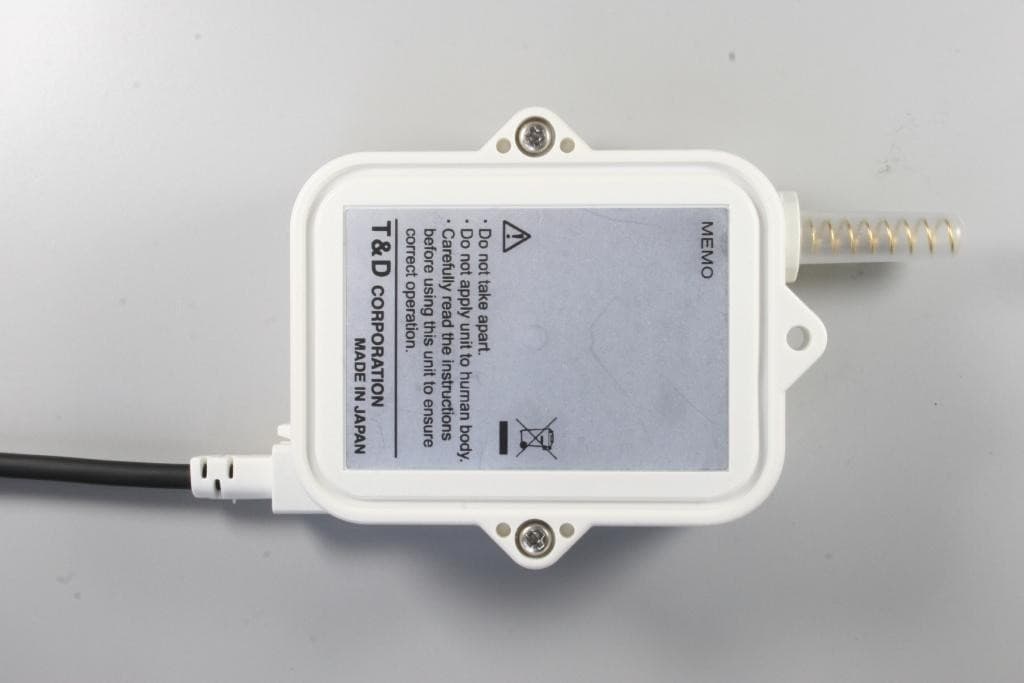
Click to zoom
Application Details
- Equipment Class
- DTS - Digital Transmission System
- Date of Grant
- Jun 13, 2011
- Application Purpose
- Original Equipment
- Date of Application
- Jun 13, 2011
- Equipment Note
- WIRELESS DATA RECORDER
- Frequency Range
- 902.93760000 - 927.12960000
- Company
- TandD Corporation
- Country
- Japan
Documents & Files
Document Text
Text extracted from the exhibit documents filed with the FCC. Open a document above to read the original.
Users Manual
Continued on Back Page. >> Part Names 2. Connecting an Input Module Insert the module into the module jack. Once the Unit recognizes the module, the LCD display will change as shown below and recording will start. (If you have purchased an RTR-505-P, the Unit has been ready for the pulse measure-ment by default, therefore recording will start upon installation of the battery.The factory default settings are as follows: Recording Interval at 10 minutes, Recording Start at Immediate Start, Recording Mo de at Endless. Make sure that the module is completely inserted until you hear a “click” sound. Set Model Number Measurement Items Input Module LCD Displayed Items (see the following section #3) Compatible Sensors RTR-505-TC Temperature Thermocouple Module (TCM-3010) Measurement, Unit of Measurement, Sensor Type, Operational Status Thermocouple: Type K, J, T, S RTR-505-Pt Temperature PT Module (PTM-3010) Measurement, Unit of Measurement, Sensor Type, Operational Status Pt100, Pt1000 RTR-505-V Voltage Voltage Module (VIM-3010) Measurement, Unit of Measurement, Operational Status Voltage Input Signal RTR-505-mA 4-20mA 4-20mA Module (AIM-3010) Measurement, Unit of Measurement, Operational Status 4-20mA Input Signal RTR-505-P Pulse Pulse Input Cable (PIC-3150) Measurement, Unit of Measurement, Operational Status - - - - 1. Installing the Battery Cover Rubber Packing Lithium Battery(inserted into tube) Screws 1 Remove the screws and open the cover.Make sure to use the proper size and type of screwdriver. (Phillips head #1 screwdriver is recommended.) 2 Insert the included battery.Do not remove the battery from its tube casing. - If using a CR2 lithium battery, the tube is not necessary. 3 Check the rubber packing for any cuts or scratches and close the cover as it was when opened. - Dust or defects on the packing can adversely affect the waterproof capacity; in this case, remove the dust or replace the pack - ing if it is damaged. - Be sure to completely close the cover. - Make sure not to over tighten the screws. (Appropriate Tightening Torque: 20N cm to 30N cm{2Kgf cm to 3Kgf cm}) Notes about Battery Installation - After inserting the battery for the fi rst time, nothing may appear or occur for about 10 seconds; this is not a malfunction. - If a new battery has been installed and nothing appears in the display, please remove and reinsert the battery. - When inserting a battery, make sure no water or foreign objects get inside the case. - Make sure that + and - are in the correct direction. About Lithium Batteries - Lithium batteries CR2 sold in stores may also be used, but if you are using in an environment below -20°C, above 60°C, or in a situation such as transportation where continued vibration is likely to occur, we strongly suggest the purchase and use of the our lithium battery LS14250. (Please purchase the optional battery set TR-11P2 in which LS14250 is included.) - When using a LS14250 type lithium battery, even though a new battery has been inserted the battery warning mark may remain on for a short time. This is due to a special characteristic of the battery. Note that the longer the battery has been in stora ge the longer the amount of time, from 10 minutes to about 1 hour, the battery warning mark will remain on. If during that time the Ba se Unit is used to get the current status of the Remote Unit, the remaining battery level will show that the battery level is low. - Please store the lithium battery LS14250 in a place that is 20 °C or less. - When changing a CR2 battery, we strongly suggest changing the rubber packing and the drying agent. Please purchase the maintenance set TR-00P1 sold separately. RTR-505 is a Remote Unit. In order to use wireless communication,it is necessary to purchase a Base Unit separately. (Compatible Base Units: RTR-500, RTR-500NW, RTR-500AW) Wireless Data Recorder RTR-505 is referred to as the “Unit” in this manual. Specifications Device Name RTR-505 Measurement Items (*1) Temperature / Voltage / 4-20mA / Pulse Recording Intervals Select from 15 choices: 1, 2, 5, 10, 15, 20, and 30 sec. / 1, 2, 5, 10, 15, 20, 30, and 60 min. Logging Capacity 16,000 Readings Recording Start Method Immediate Start / Programmed StartRecording Mode Endless / One Time (Factory Default Setting: Endless) LCD Displayed Items Measurement, Recording Status, Recording Mode, Battery Life Warning, Unit of Measurement, Full (Logging Capacity FULL), Sensor Unconnected, Input Module Unconnected, Measurement Range Exceeded, Display Range Exceeded) Communication Interfaces Wireless Communication / Optical Communication Wireless Communication Specifi cations RF Power 7mW Radio Standard Specifi cations FCC Part15 Section247 / IC RSS-210Frequency Range : 902 to 928MHz Transmission Range About 150m (500ft) (if direct and unobstructed)Communication Speed About 2 min. (when downloading 1 unit at full logging capacity) Optical Communication Speed About 160 sec. (when downloading 1 unit at full logging capacity at 2400bps) Power Lithium Battery (LS14250) / Lithium Battery (CR2) (*2) Battery Life (*3) About 10 months (for temperature measurement) Waterproof Capacity Splash proof (rated for use in daily life) (*4) Dimensions H62 W47 D19mm (excluding protrusions and sensor part) Weight About 55g (including battery / excluding input module) Operating Temperature Range Unit Temp Resistance: - 40 to 80 C (Unit temp resistance and measurement range is -40 to 80 C but wireless communication cannot occur in an environment of less than -30 C.) Other A Base Unit is required (sold separately).(Compatible Base Units: RTR-500, RTR-500NW, RTR-500AW) (*1) Measurement items other than Pulse will have different measurement range depending on the input module and sensor to be connected. For details, see the User s Guide included with the input module. (*2) The included lithium battery (LS14250) is not sold in stores. Please purchase the optional battery set for low-temperature use (TR-11P2) for replacement. (*3) …
Text truncated - open the document above for the full version.
External Photos
T&D CORPORATION FCC ID: SRD50020 EXTERNAL PHOTOS
ID Label/Location Info
64 21.4 47 58 66 19 設計 製図 検図 承認 内 容 年 月 日 担当 株式会社 ティアンドデイ 材料 処理 品名 製品コード 0 0.5 0.5 6 6 30 30 120 120 350 350 1000 ±0.05 ±0.1 ±0.5 ±0.8 1 2 3 ±0.2 ±0.3 差 公 度 尺 量 数 Doc.No.851-0476-7030 1:1 RTR-505(US) 外観図 福田 11.04.04
Internal Photos
T&D CORPORATION FCC ID: SRD50020 INTERNAL PHOTOS
Operational Description
Outline of Circuit (RF BLOCK) Each Part’s Functions (1)Transceiver(IC200) Transceiver(IC200)consists of five parts: Reference oscillator, Frequency synthesizer, Modulation, transmitter, and receiver. 1 Reference oscillator Reference signal is generated by crystal oscillator 13.1072MHz(X200). 2 Frequency synthesizer Frequency synthesizer consists of frequency divider, reference frequency divider, phase comparator, charge pump and VCO. Oscillating frequency is set by a control signal from the control CPU (ICI). Output frequency Lo1 of VCO is eight-ninth of the Rf, and Lo2 is one-ninth of the Rf. 3 Modulation Baseband signal is FSK modulated. Bit Rate is 8192bps Deviation is 204.8kHz 4 Transmitter FSK signal is up-converted to RF through the 1 st mixer and the 2 nd mixer, then supplied to Transmitter Power Amplifier. It is programmable to set the output of power amplifier and it is set by the control CPU (ICI). To regulate transmission power, supply voltage is regulated to 1.8V in power source of Power Amp (in IC200). 5 Receiver RF input signal is sent to the 1 st mixer after amplified by Low Noise Amplifier (LNA), then converted to Intermediate Frequency RF*1/9. Next, it is converted to baseband by the 2 nd mixer, and demodulated via channel filter. (2)RF Output Part RF signal which is input or output to the antenna (CN3) is band-limited by SAW Filter (F1). This improves selectivity for receiving and unnecessary radiation. (3)Controller Part The CPU (IC1) controls followings: 1. Control Transceiver A) Frequency synthesizer setting B) RF output power setting C) Transmitting / Receiving Control D) Communication Control 2. Serial Communication Control 3. Power Monitor 4. Others (3)Power Transceiver power is regulated at 3V. (External Sensor BLOCK) Option Sensor module comes into following four types. Temperature Measurement Voltage Measurement Current Measurement Pulse Count Main unit communicates with each sensor module via serial communication (UART) to get readings. About Pulse Count, pulse signal is counted directly by CPU (IC1) after level adjustment and filtering.
Parts List/Tune Up Info
Code Material Parts Number Maker Qty Reference 13004767102 PCB RTR-505.PCB AIN 1 PCB1 14004032110 Terminal TR-51(+)terminal --- 1 CN1 14004037030 Terminal TR-5/RTR-5(-)terminal --- 1 CN2 14004751010 LCD 912-A42A-0224 E&E 1 LCD1 20101000601 Resistor RK73B1ETTP101J KOA 7 R9,R15,R16,R18,R24,R25,R27 20101001600 Resistor RK73B1JTTD102J KOA 1 R44 20101002400 Resistor RK73H1JTTD1002F KOA 1 R19 20101002600 Resistor RK73B1JTTD103J KOA 6 R31,R36,R37,R39,R40,R42 20101003600 Resistor RK73B1JTTD104J KOA 7 R5,R6,R17,R20,R21,R61,R62 20101004600 Resistor RK73B1JTTD105J KOA 2 R7,R11 20101009401 Resistor RK73H1ETTP1R00F KOA 1 R1 20101009600 Resistor RK73B1JTTD1R0J KOA 1 D1 20102001600 Resistor RK73B1JTTD202J KOA 2 R8,R32 20102003600 Resistor RK73B1JTTD204J KOA 1 R22 20104700600 Resistor RK73B1JTTD471J KOA 1 R30 20104701600 Resistor RK73B1JTTD472J KOA 1 R33 20104702600 Resistor RK73B1JTTD473J KOA 3 R12,R13,R14 20105103600 Resistor RK73B1JTTD514J KOA 1 R28 20108203600 Resistor RK73B1JTTD824J KOA 1 R3 20106801400 Resistor RK73H1ETTP682F KOA 3 R2,R23,R26 20131000600 Resistor SG73S1JTTD101J KOA 1 R4 20801002803 Capacitor TEESVA1C106M NEC 1 C12 20801081802 Capacitor TEESVP1A105M8R NEC 1 C14 20924730900 Capacitor FC0H473ZFTBR24 NEC 1 C7 21021503600 Capacitor GRM1882C1H150JA01D Murata 2 C5,C6 21021023701 Capacitor GRM188B11H102KA01D Murata 1 C10 21021031700 Capacitor GRM155B11E103KA01D Murata 1 C36 21021040700 Capacitor GRM155B31C104KA87D Murata 1 C35 21021041701 Capacitor GRM188B11E104KA01D Murata 6 C2,C4,C8,C11,C13,C20 21021050700 Capacitor LMK107BJ105KA-T YAIYO YUDEN 2 C9,C19 21021050701 Capacitor GRM155B31A105KE15D Murata 2 C31,C32 21021060800 Capacitor JMK107BJ106MA-T YAIYO YUDEN 1 C18 21021583200 Capacitor GRM1884C1H1R5CZ01D Murata 1 Z1 21022003600 Capacitor GRM1882C1H200JA01D Murata 1 C43 21022203601 Capacitor GRM1552C1H220JZ01D Murata 3 C16,C17,C39 21022213602 Capacitor GRM1882C1H221JA01D Murata 1 C3 21022240700 Capacitor GRM155B10J224KE01D Murata 1 C33 21022260800 Capacitor JMK212BJ226MG-T YAIYO YUDEN 1 C21 21023313600 Capacitor GRM1882C1H331JA01D Murata 1 C1 21024730701 Capacitor GRM155B11A473KA01D Murata 1 C34 21026813600 Capacitor GRM1552C1H681JA01D Murata 1 C37 21422700001 Diode EDZTE6127B ROHM 1 D5 21440413101 Diode RB520S-30 ROHM 3 D2,D3,D4 21722226300 Transistor 2SC2412K-T146Q ROHM 1 Q2 21782123300 Transistor RN2402 TOSHIBA 1 Q1 21901100003 PhotoTransistor PS1101W STANLEY 1 PC2 21901100005 PhotoTransistor PT17-21B EVERLIGHT 1 PC1 22021115200 FET SSM3K15FU(TE85L_F) TOSHIBA 3 QF1,QF3,QF4 22051126300 FET SSM3J15FS(TE85L_F) TOSHIBA 1 QF2 22710265500 REG S-817A22ANB SII 1 IC5 22711464500 REG R1180Q301C-TR RICOH 1 IC6 22925000008 VolDet S-80822CNNB-B8H-T2 SII 1 IC4 22935000005 IC SX1211I084TRT SEMTECH 1 IC200 23199001400 IC TC7WH14FK TOSHIBA 2 IC3,IC7 23363001901 EEPROM 24LC256T-I/SN MicroChip 1 IC2 23501000025 CPU MNBEF63GXWUB Panasonic 1 IC1 24026303103 IrLED AN1102W STANLEY 1 DS1 24943000101 Connector MM8130-2600 Murata 1 CN3 25100005001 Thermistor TCT3GH103H370H TATEYAME KAGAKU 1 TH1 25308131500 Oscillator NX5032SA-13.1072MHz NDK 1 X200 25308327200 Oscillator TFX-02-32.768KHz_10ppm River Eletec 1 X2 25338800400 Oscillator CSTCE8M00G52-R0 Murata 1 X1 25401015000 Inductor LQW15ANR10J00D Murata 1 L3 25404705000 Inductor LQW18AN47NG00D Murata 1 L5 25406882000 Inductor LQW18AN6N8C00D Murata 1 L6 25406885000 Inductor LQW15AN6N8G00D Murata 2 L1,L2 25408286000 Inductor LL1005-FHL8N2J TOKO 1 L4 25659172301 Filter WF998D0915CE NDK 1 F1 25898011001 FUSE FCC16801ABTP KAMAYA 1 R10 Blank 9 C15,C38,C40,C41,C42,DS2,R34,R38
Test Report
FCC PART 15.247 AND IC ICES-003 TEST REPORT DIGITAL SPREAD SPECTRUM Applicant T&D CORPORATION Address 817-1 SHIMADACHI MATSUMOTO 390-0852 JAPAN FCC ID SRD50020 IC 5558A-50020 Model Number RTR-505 Product Description WIRELESS DATA RECORDER Date Sample Received 4/21/2011 Date Tested 5/17/2011 Tested By Joe Scoglio Approved By Mario R. de Aranzeta Report Number 809AUT11TestReport.doc Test Results PASS FAIL THE ATTACHED REPORT SHALL NOT BE REPRODUCED EXCEPT IN FULL WITHOUT THE WRITTEN APPROVAL OF TIMCO ENGINEERING, INC. 849 NW State Road 45 Newberry, FL 32669 USA Ph: 888.472.2424 or 352.472.5500 Fax: 352.472.2030 Email: [email protected] Website: www.timcoengr.com Testing Certificate # 0955-01 APPLICANT: T&D CORPORATION FCC ID: SRD50020 IC: 5558A-50020 REPORT: T\T&D CORP_SRD\809AUT11\809AUT11TestReport.doc Page 2 of 20 Mdea 3.14.2008 TABLE OF CONTENT GENERAL REMARKS ............................................................................................................................. 3 GENERAL INFORMATION ...................................................................................................................... 4 EMC EQUIPMENT LIST.......................................................................................................................... 5 TEST PROCEDURES .............................................................................................................................. 6 RADIATION INTERFERENCE ................................................................................................................. 7 POWER LINE CONDUCTED INTERFERENCE ...................................................................................... 10 OCCUPIED BANDWIDTH ..................................................................................................................... 11 POWER OUTPUT ................................................................................................................................. 13 SPURIOUS EMISSIONS AT ANTENNA TERMINALS .............................................................................. 14 RADIATED SPURIOUS EMISSIONS INTO ADJACENT RESTRICTED BAND .......................................... 16 POWER SPECTRAL DENSITY ............................................................................................................... 20 APPLICANT: T&D CORPORATION FCC ID: SRD50020 IC: 5558A-50020 REPORT: T\T&D CORP_SRD\809AUT11\809AUT11TestReport.doc Page 3 of 20 Mdea 3.14.2008 GENERAL REMARKS The attached report shall not be reproduced except in full without the written permission of Timco Engineering Inc. The test results relate only to the items tested. Summary The device under test does: fulfill the general approval requirements as identified in this test report not fulfill the general approval requirements as identified in this test report Attestations This equipment has been tested in accordance with the standards identified in this test report. To the best of my knowledge and belief, these tests were performed using the measurement procedures described in this report. All instrumentation and accessories used to test products for compliance to the indicated standards are calibrated regularly in accordance with ISO 17025: 2005 requirements. Testing Certificate # 0955-01 I attest that the necessary measurements were made, under my supervision, at: Timco Engineering Inc. 849 NW State Road 45 Newberry, Fl 32669 Authorized Signatory Name: Mario de Aranzeta C.E.T. Compliance Engineer/ Lab. Supervisor Date: June 13, 2011 APPLICANT: T&D CORPORATION FCC ID: SRD50020 IC: 5558A-50020 REPORT: T\T&D CORP_SRD\809AUT11\809AUT11TestReport.doc Page 4 of 20 Mdea 3.14.2008 GENERAL INFORMATION DUT Specification Applicable Standard Part 15.247, RSS-210, RSS-GEN DUT Description WIRELESS DATA RECORDER FCC ID SRD50020 IC: 5558A-50020 Model RTR-505 Operating Frequency TX: 902 – 928 MHz DUT Power Source 110–120Vac/50– 60Hz DC Power Battery Operated Exclusively Test Item Prototype Pre-Production Production Type of Equipment Fixed Mobile Portable Antenna Helical Antenna Test Facility Timco Engineering Inc. located at 849 NW State Road 45 Newberry, FL 32669 USA. Test Conditions Temperature: 26ºC Relative humidity: 50% Test Exercise The DUT was placed in continuous transmit mode of operation. Test Supporting Equipment Supporting Device Manufacturer Model / FCC ID Serial Number N/A APPLICANT: T&D CORPORATION FCC ID: SRD50020 IC: 5558A-50020 REPORT: T\T&D CORP_SRD\809AUT11\809AUT11TestReport.doc Page 5 of 20 Mdea 3.14.2008 EMC EQUIPMENT LIST Device Manufacturer Model Serial Number Cal/Char Date Due Date 3-Meter Semi- Anechoic Chamber Panashield N/A N/A Listed 3/10/10 3/10/12 Antenna: Dipole Kit Electro- Metrics TDA-30/1-4 153 CHAR 6/10/09 6/10/11 Antenna: Passive Loop EMC Test Systems EMCO 6512 9706-1211 CAL. 6/1/09 6/2/11 Frequency Counter HP 5385A 2730A03025 CAL 8/4/09 8/4/11 Hygro- Thermometer Extech 445703 0602 CAL 1/30/10 1/30/12 Modulation Analyzer HP 8901A 3435A06868 CAL 5/26/09 5/26/11 Analyzer Tan Tower Preamplifier HP 8449B-H02 3008A00372 CAL 11/21/09 11/21/11 Analyzer Tan Tower Quasi- Peak Adapter HP 85650A 3303A01690 CAL 11/22/09 11/22/11 Analyzer Tan Tower RF Preselector HP 85685A 3221A01400 CAL 11/21/09 11/21/11 Analyzer Tan Tower Spectrum Analyzer HP 8566B Opt 462 3138A07786 3144A20661 CAL 11/24/09 11/24/11 Temperature Chamber Tenney Engineering TTRC 11717-7 CHAR 4/25/10 4/25/12 APPLICANT: T&D CORPORATION FCC ID: SRD50020 IC: 5558A-50020 REPORT: T\T&D CORP_SRD\809AUT11\809AUT11TestReport.doc Page 6 of 20 Mdea 3.14.2008 TEST PROCEDURES Radiation Interference: ANSI C63.4-2003 using a spectrum analyzer, a preselector, a quasi-peak adapter, and an appropriate antenna. The analyzer was calibrated in dB above a microvolt at the output of the antenna. The resolution bandwidth was 100 kHz with an appropriate sweep speed and the video bandwidth was 300 kHz up to 1 GHz and 1 MHz with a video BW of 3 MHz above 1 GHz. When an emission was foun…
Text truncated - open the document above for the full version.
Contact Information
Applicant
Akemi Oana(Sales Department)
Test Firm
Timco Engineering, Inc.Bruno Clavier
Technical Specifications
| # | Rule Parts | Frequency Range | Power Output |
|---|---|---|---|
| 1 | 15C | 902.9376 MHz - 927.1296 MHz | 3.00 mW |
Other Applications from TandD Corporation
SRD50150
Sep 26, 2024Data Logger
Equipment Class
DTS - Digital Transmission System
SRD50140
Apr 08, 2023Data Logger
Equipment Class
DTS - Digital Transmission System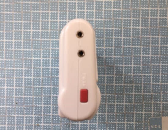
SRD50110
Jul 11, 2021Data Logger
Equipment Class
DTS - Digital Transmission System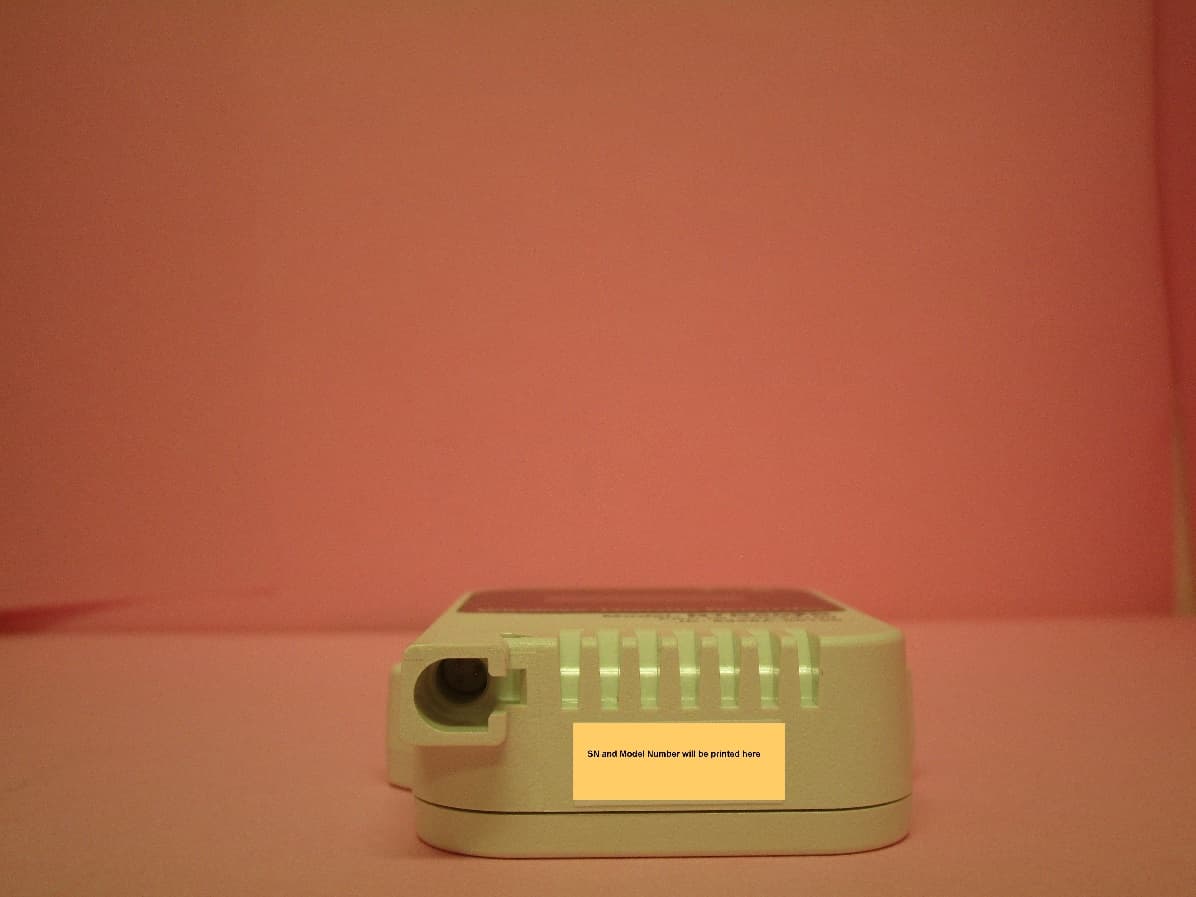
SRD50100
Dec 02, 2020Data Logger Remote Unit
Equipment Class
DTS - Digital Transmission System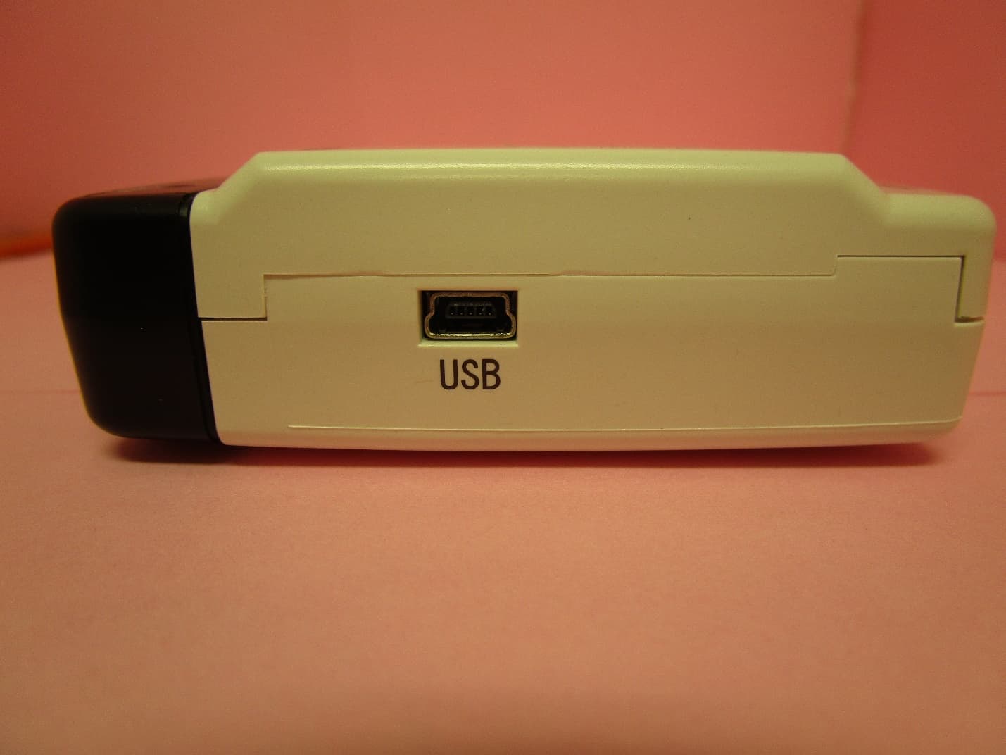
SRD10100
Dec 02, 2020Data Logger Base Unit
Equipment Class
DTS - Digital Transmission System