SRD50040WIRELESS CO2 RECORDER
TandD Corporation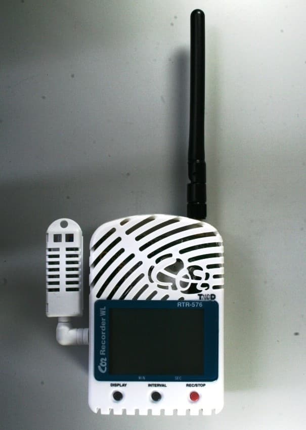
Click to zoom
Application Details
- Equipment Class
- DTS - Digital Transmission System
- Date of Grant
- Oct 29, 2012
- Application Purpose
- Original Equipment
- Date of Application
- Oct 29, 2012
- Equipment Note
- WIRELESS CO2 RECORDER
- Frequency Range
- 902.00000000 - 928.00000000
- Company
- TandD Corporation
- Country
- Japan
Documents & Files
Document Text
Text extracted from the exhibit documents filed with the FCC. Open a document above to read the original.
Users Manual
Part Names and LCD Display Thank you for purchasing our product. To ensure safe and proper operation, please read this manual thoroughly before use. RTR-576 Package Contents RTR-576 -H Package Contents • Wireless CO2 Recorder (RTR-576)• Temperature/Humidity Sensor (THA-3001)• AC Adaptor (AD-0638)• USB Communication Cable (US-15C)• AA Alkaline Battery x 4• User's Manual (Warranty Included) • Wireless CO2 Recorder (RTR-576)• High Precision Temperature/Humidity Sensor (HHA-3151) • AC Adaptor (AD-0638)• USB Communication Cable (US-15C)• AA Alkaline Battery x 4• User's Manual (Warranty Included) http://www.tandd.com/ © Copyright T&D Corporation. All rights reserved. 2012.07. 1650480XXXX 1st EditionPrinted on recycled paper. Notes about Operation This product has been designed for use in normal living conditions, and is not suited for controlled environments such as a CO2 incubator. When measuring outdoors, avoid exposure to sunlight, dust, rain, or wind. Also make sure to use in the operating environment indicated in the speci fi cations. This product cannot measure CO or O2. Do not use it for purposes such as avoiding O2 de fi ciency, CO intoxication or any other health related purpose. For one to two weeks after installation of the unit, CO2 concentration measurements may fl uctuate suddenly. This is due to the normal operation of Auto Calibration and is not a malfunction of the RTR-576.Do not use or store the unit in areas exposed to direct sunlight and abrupt changes in temperature.Do not allow the unit to become wet. Do not use or store the unit in places where condensation occurs.To help prevent deterioration of the unit, do not use or store the unit in areas exposed to cigarette smoke, gas, and dust in the air.Do not expose the Unit to a strong impact. This will adversely affect measurement accuracy and may cause the case to break resulting in bodily injury.The measurement accuracy of the CO2 sensor can not be guaranteed for CO2 concentrations of 5,000ppm or more.As a Remote Unit, RTR-576 requires a Base Unit to carry out wireless communication.(Compatible Base Units: RTR-500, RTR-500NW/500AW, RTR-500DC)Please set up the Base Unit fi rst before the RTR-576. AntennaCO2 Sensor Area (Internal)LCD Display Operation Buttons Button Button Button Battery CoverTemperature and Humidity Sensor Jack AC Adaptor JackUSB Communication Cable JackSerial Communication Cable Jack (RS-232C)External Alarm Terminal (EXT ALM) Switch [REC] Mark Shows recording statusON: Recording in progressBLINKING: Waiting for programmed startOFF: Recording stopped Data Scale After every 2,000 readings the scale will be marked from left to right. Logging capacity is 8,000 readings. [COM] Mark Shows communication status but not displayed normally.ON: The unit is connected to a PC with a USB cable.RAPID BLINKING: The unit is in communication with the computer via USB or infrared communication. Rec. Mode Recording mode settings can be made by using the supplied software. Endless: Upon reaching the logging capacity of 8,000 readings, the oldest data will be overwritten and recording will continue. One Time: Upon reaching the logging capacity of 8,000 readings, recording will automatically stop and in the LCD the current measurement and the word “FULL” will alternately appear. Battery Mark Shows source of power and voltage level. (See "Interpreting the Battery Mark" for details.) Current Tempera-ture and Humidity Readings Area Shows the current readings for temperature (°C / °F) and humidity (%RH). Press-ing the button will change the measurement item to be displayed. This area is also used to display messages. Current CO2 Readings Area Shows the current readings for CO2 concentration (ppm). This area is also used to display messages. Wireless CO2 Recorder RTR-576 User's Manual Setting up the RTR-576 Button Operations Do not connect an RTR-576 to your computer before fi rst installing the supplied software that comes with the Base Unit you are using. Connect the Sensor Turn ON the Power AC AdaptorWhen measuring and recording over long periods of time, please use a supplied AC adaptor.Four AA Alkaline BatteriesIf running on only batteries, the estimated battery life is about two days. Keeping batteries in the unit allows a backup source of power for when and if electrical power is cut from the AC adaptor. • Note: When using batteries as a backup power supply, it is recommended to replace them approximately once every two years to avoid battery leakage. Install the Battery If battery power is lost, all recorded data stored in the unit will be erased. Do not leave the unit without batteries. 1. Remove the battery cover from the back of the unit. While pressing down on the triangular mark, slide the cover to the bottom of the unit. Lift off the cover. 2. Insert the supplied batteries. • Make sure to use new batteries of the same kind.• Make sure not to mistake + / -.• Do not insert or change batteries with wet hands.• Be sure to completely close the cover. Messages and Display on the LCD Settings Messages Button LockWhen "Button Lock" has been set to ON in the CO2 Recorder for Windows, operational buttons are not active.Memory FullWhen recording mode has been set to “One Time” and the unit reaches its logging capacity of 8,000 readings, the measurement and the message [FULL] will alternately appear in the LCD. Stop recording and download the recorded data before re-starting recording. "Endless" mode does not have the Memory Full status. Turn on the switch. After setting up the power supply, turn on the switch. • See Button Operations for notes about turning off the switch. "ON" position Warm-up Time for CO2 SensorAfter switching on the unit, it will take about one minute to display the normal CO2 concentration. Register Remote Units Register RTR-576 as a Remote Unit by using the software supplied with the Base Unit. After connecting an RTR-576 to your computer via USB cable, carry out registration using your software: Settings Util…
Text truncated - open the document above for the full version.
External Photos
APPLICANT: T&D CORPORATION FCC ID: SRD50040 EXTERNAL PHOTOS
ID Label/Location Info
66 96 108.9 202.5 EXTPOWER DC6V 46 TANDD REC/STOPINTERVALDISPLAY EXTALM POWER COM USB 締付けトルク2.5kgf・cm なべM2X8BタイトLRタンバープルーフ(3ヶ所) 設計 製図 検図 承認 内 容 年 月 日 担当 株式会社 ティアンドデイ 材料 処理 品名 製品コード 0 0.5 0.5 6 6 30 30 120 120 350 350 1000 ±0.05 ±0.1 ±0.5 ±0.8 1 2 3 ±0.2 ±0.3 差 公 度 尺 量 数 1:1 岡崎 12.03.07 RTR-576(US)外観図 Doc.No.851-0480-7050
ID Label/Location Info
材料:ポリエステルフィルム 色:シルバー(銀マ ット)厚さ100ミ クロン 文字色: 黒 ラミ ネート 加工の事 岡崎 12 03 07 Doc.No.852-0480-7020 図名:RTR-576(US)シリアルシール版下 日付:2012/03/07 作成:岡崎 シリアルNo.表記・・・32Cは固定で40001~5FFFFの16進数 (尺度2:1) (尺度1:1)
Internal Photos
APPLICANT: T&D CORPORATION FCC ID: SRD50040 INTERNAL PHOTOS
Parts List/Tune Up Info
RTR-576 Base-Board PartsList 2012/7/4 Material Parts Name Manufacturer Qua Reference P.C.B 13004648101.PCB --- 1 PCB1battery-terminal RTR-500GSM_Terminal(+) --- 2 JP1,JP3 battery-terminal RTR-500GSM_Terminal(-) --- 2 JP2,JP4 Resitor RK73Z1JTTD KOA 1 R23Resitor RK73H1JTTD1000F KOA 2 R11,R12Resitor RK73B1JTTD101J KOA 4 R1,R2,R37,R38Resitor RK73B1JTTD102J KOA 1 R24Resitor RK73B1JTTD103J KOA 4 R9,R10,R25,R34Resitor RK73B1JTTD104J KOA 10 R5,R14,R18,R19,R22,R26,R28,R32,R33,R53Resitor RK73B1JTTD471J KOA 2 R13,R20Resitor RK73B1JTTD514J KOA 2 R36,R39Resitor RK73G1JTTD7502F KOA 1 R17Resitor RN732ATTD1202F50 KOA 1 R21Resitor RK73B1JTTD220J KOA 1 R40Resitor RK73B2BTTD100J KOA 1 R35Resitor SR73W3ATTDR100F KOA 1 R16Capacitor TEESVA0J107M8R NEC 1 C9Capacitor TEESVC1C476M12R NEC 1 C25Capacitor EMVA160ADA221MF80G NIPPON CHEMI-CON 1 C13Capacitor EMVA4R0ADA471MF80G NIPPON CHEMI-CON 1 C8Capacitor FC0V224ZFTBR24 NEC 1 C30Capacitor GRM188B11H102KA01D Murata 2 C28,C29Capacitor GRM188B11E104KA01D Murata 3 C7,C18,C19Capacitor GRM155B31A105KE15D Murata 2 C14,C15Capacitor GRM219F11E105ZA01D Murata 1 C26Capacitor GRM188F11C105ZA01D Murata 4 C1,C2,C3,C4Capacitor EMK316F106ZL-T TAIYO YUDEN 1 C16Capacitor LMK212F106ZG-T TAIYO YUDEN 4 C6,C17,C23,C24Capacitor TMK325BJ106MM-T TAIYO YUDEN 1 C27Capacitor GRM31CB30J226KE18L Murata 1 C21Capacitor GRM188F11C474ZA01D Murata 2 C11,C12Capacitor GRM1885C1H680JA01D Murata 1 C20Diode DF2S30FS(TPL3) TOSHIBA 1 D11Diode HZM6.2ZMWA Hitachi 1 D5Diode RB521S-30 ROHM 3 D9,D13,D14Diode RB520S-30 ROHM 4 D3,D4,D8,D12Diode CMS04 TOSHIBA 4 D1,D2,D6,D10 Transistor 2SA1182-TE85L TOSHIBA 1 Q1FET SSM6J51TU(TE.F) TOSHIBA 1 IC1FET SSM6K18TU(TE.F) TOSHIBA 1 IC6FET SSM3K15FU(TE85L_F) TOSHIBA 4 QF1,QF3,QF4,QF7FET SSM3K7002FU(TE85L_F) TOSHIBA 1 QF6FET SSM3J15FS(TE85L_F) TOSHIBA 1 QF8FET TPCS8303 TOSHIBA 1 QF2Regulator R1163D331B-TR-F RICOH 2 IC3,IC4Regulator R1500H050B-F RICOH 1 IC8DC/DC_CONV XC9104D093MR TOREX 1 IC5Switch CMS-2214C copal 1 SW1Connector S04B-PASK-2(LF)(SN) JST 1 CN7Connector F604-MGN-D047-24-P Cherng Weei 1 CN6Connector P122-SGP-025/000/025-05 Cherng Weei 3 CN1,CN2,CN3Connector P321-R2GP-030/000/028-08 Cherng Weei 1 CN5Connector M04-260DJ Technical electron 1 CN4 Inductor LQH55PN100MR0 Murata 1 L1Filter BLM18SG221TN1 Murata 2 L4,L5Filter NFM21CC223R1H3 Murata 5 LF1,LF2,LF3,LF4,LF5
Parts List/Tune Up Info
RTR-576 CPU-Board PartsList 2012/7/4 Material Parts Name Manufacturer Qua Reference P.C.B 13004648202.PCB --- 1 PCB1LCD 0464_LCD_R200 YEEBOH 1 LCD1Resitor RK73Z1JTTD KOA 3 R13,R38,R47Resitor RK73B1JTTD101J KOA 2 R39,R42Resitor RK73B1JTTD103J KOA 8 R1,R3,R8,R9,R23,R26,R32,R37Resitor RK73B1JTTD104J KOA 8 R20,R28,R29,R31,R33,R41,R43,R44Resitor RK73B1JTTD105J KOA 2 R10,R45Resitor RK73B1JTTD100J KOA 2 R34,R36Resitor RK73B1JTTD202J KOA 3 R12,R15,R18Resitor RK73B1JTTD203J KOA 2 R21,R30Resitor RK73B1JTTD204J KOA 1 R16Resitor RK73B1JTTD330J KOA 2 R2,R4Resitor RK73B1JTTD514J KOA 3 R11,R14,R17Resitor RK73B2ATTD1R0J KOA 1 R40Capacitor TEESVA0J107M8R NEC 1 C21Capacitor EMVA4R0ADA221MF55G NIPPON CHEMI-CON 1 C22Capacitor GRM188B11H102KA01D Murata 5 C17,C19,C24,C34,C35Capacitor GRM188B11H103KA01D Murata 3 C13,C16,C18Capacitor GRM188B11E104KA01D Murata 14 C1,C2,C4,C5,C6,C7,C8,C9,C10,C11,C12,C20,C31,C37Capacitor LMK107BJ105KA-T TAIYO YUDEN 4 C25,C27,C29,C30Capacitor GRM1882C1H200JZ01D Murata 1 C15Capacitor GRM1882C1H221JA01D Murata 1 C3Diode HZM6.2ZMWA Hitachi 3 D1,D2,D14Diode RB521S-30 ROHM 8 D4,D5,D6,D7,D8,D11,D12,D13Diode RB520S-30 ROHM 2 D9,D10Transistor 2SC2412K-T146Q ROHM 1 Q1FET SSM3K15FU(TE85L_F) TOSHIBA 3 QF2,QF3,QF5FET SSM3J15FS(TE85L_F) TOSHIBA 2 QF1,QF4Regulator XC6202P352MR-N TOREX 1 IC6Reset IC S-80822CNNB-B8H-T2 SII 1 IC4IC TC4S71F TOSHIBA 1 IC9IC TC7MBL6353SFK TOSHIBA 2 IC3,IC5EEPROM 24LC512T-I/SMG Microchip 1 IC2CPU S1C17602 EPSON 1 IC1IC CP2103-GM Silicon Labs 1 IC7Switch SKQYPAE010 ALPS 3 SW1,SW2,SW3Connector 02-641P0-33BKA EX Company 1 CN6Connector P625-M6GN-030/069-24-P Cherng Weei 1 CN3Connector TCX0101-110177 HOSIDEN 1 CN1Connector TCX3171-010100 HOSIDEN 1 CN2Oscillator TFX-02-32.768KHz_10ppm RIVER ELETEC 1 X2 Oscillator CSTCE8M00G52-R0 Murata 1 X1Filter BLM18SG221TN1 Murata 3 L1,L2,L3Filter NFM21CC223R1H3 Murata 2 LF1,LF2Filter 985BH-1007=P2 TOKO 1 T1
Test Report
FCC PART 15.247 AND IC RSS-210 TEST REPORT DIGITAL SPREAD SPECTRUM Applicant T&D CORPORATION Address 817-1 SHIMADACHI MATSUMOTO 390-0852 FCC ID SRD50040 IC 5558A-50040 Model Number RTR-576 Product Description WIRELESS CO2 RECORDER Date Sample Received 7/30/2012 Date Tested 8/10/2012 Tested By John A. Day Approved By Mario R. de Aranzeta Report Number 1898AUT12TestReport.doc Test Results PASS FAIL THE ATTACHED REPORT SHALL NOT BE REPRODUCED EXCEPT IN FULL WITHOUT THE WRITTEN APPROVAL OF TIMCO ENGINEERING, INC. 849 NW State Road 45 Newberry, FL 32669 USA Ph: 888.472.2424 or 352.472.5500 Fax: 352.472.2030 Email: [email protected] Website: www.timcoengr.com Testing Certificate # 0955-01 APPLICANT: T&D CORPORATION FCC ID: SRD50040 IC: 5558A-50040 REPORT #: T\T&D CORP_SRD\1898AUT12\1898AUT12TestReport.doc Page 2 of 15 Mdea 3.14.2008 TABLE OF CONTENT GENERAL REMARKS ............................................................................................................................. 3 GENERAL INFORMATION ...................................................................................................................... 4 EMC EQUIPMENT LIST.......................................................................................................................... 5 TEST PROCEDURES .............................................................................................................................. 6 RADIATION INTERFERENCE ................................................................................................................. 7 POWER LINE CONDUCTED INTERFERENCE ...................................................................................... 10 OCCUPIED BANDWIDTH ..................................................................................................................... 12 POWER OUTPUT ................................................................................................................................. 13 SPURIOUS EMISSIONS AT ANTENNA TERMINALS .............................................................................. 14 POWER SPECTRAL DENSITY ............................................................................................................... 15 APPLICANT: T&D CORPORATION FCC ID: SRD50040 IC: 5558A-50040 REPORT #: T\T&D CORP_SRD\1898AUT12\1898AUT12TestReport.doc Page 3 of 15 Mdea 3.14.2008 GENERAL REMARKS The attached report shall not be reproduced except in full without the written permission of Timco Engineering Inc. The test results relate only to the items tested. Summary The device under test does: fulfill the general approval requirements as identified in this test report not fulfill the general approval requirements as identified in this test report Attestations This equipment has been tested in accordance with the standards identified in this test report. To the best of my knowledge and belief, these tests were performed using the measurement procedures described in this report. All instrumentation and accessories used to test products for compliance to the indicated standards are calibrated regularly in accordance with ISO 17025: 2005 requirements. Testing Certificate # 0955-01 I attest that the necessary measurements were made, under my supervision, at: Timco Engineering Inc. 849 NW State Road 45 Newberry, Fl 32669 Authorized Signatory Name: Mario de Aranzeta C.E.T. Compliance Engineer/ Lab. Supervisor Date: 8/28/2012 APPLICANT: T&D CORPORATION FCC ID: SRD50040 IC: 5558A-50040 REPORT #: T\T&D CORP_SRD\1898AUT12\1898AUT12TestReport.doc Page 4 of 15 Mdea 3.14.2008 GENERAL INFORMATION DUT Specification Applicable Standard Part 15.247, RSS-210, RSS-GEN DUT Description WIRELESS CO2 RECORDER FCC ID SRD50040 IC 5558A-50040 Model RTR-576 Operating Frequency TX: 902-928 RX: Same DUT Power Source 110–120Vac/50– 60Hz DC Power Battery Operated Exclusively Test Item Prototype Pre-Production Production Type of Equipment Fixed Mobile Portable Antenna Connector FCC Rules require that the antenna connector be unique. Antenna Test Facility Timco Engineering Inc. located at 849 NW State Road 45 Newberry, FL 32669 USA. Test Conditions Temperature: 26ºC Relative humidity: 50% Test Exercise The DUT was placed in continuous transmit mode of operation. Test Supporting Equipment Supporting Device Manufacturer Model / FCC ID Serial Number N/A APPLICANT: T&D CORPORATION FCC ID: SRD50040 IC: 5558A-50040 REPORT #: T\T&D CORP_SRD\1898AUT12\1898AUT12TestReport.doc Page 5 of 15 Mdea 3.14.2008 EMC EQUIPMENT LIST Device Manufacturer Model Serial Number Cal/Char Date Due Date 3/10-Meter OATS TEI N/A N/A 12/31/11 12/31/13 3-Meter OATS TEI N/A N/A 12/31/11 12/31/13 Antenna: Passive Loop EMC Test Systems EMCO 6512 9706-1211 06/14/12 06/14/14 Frequency Counter HP 5385A 2730A03025 08/17/11 08/17/13 Frequency Counter HP 5352B 2632A00165 06/22/11 06/22/13 Digital Multimeter Fluke 77 43850817 02/22/12 02/22/13 Digital Multimeter Fluke FLUKE-77-3 79510405 06/13/11 06/13/13 Frequency Counter HP 5385A 3242A07460 06/22/11 06/22/13 3-Meter Semi- Anechoic Chamber Panashield N/A N/A 12/31/11 12/31/13 Temperature Chamber Thermotron Corp. S1.2 Mini Max 25-1420-09 07/03/12 07/03/14 Analyzer Tan Tower Preamplifier HP 8449B-H02 3008A00372 11/21/09 10/28/13 Analyzer Tan Tower Quasi- Peak Adapter HP 85650A 3303A01690 11/22/09 10/28/13 Analyzer Tan Tower RF Preselector HP 85685A 3221A01400 11/21/09 10/28/13 Analyzer Tan Tower Spectrum Analyzer HP 8566B Opt 462 3138A07786 3144A20661 11/24/09 10/28/13 Antenna: Biconnical Eaton 94455-1 1057 05/31/11 05/31/13 Antenna: Log- Periodic Eaton 96005 1243 05/31/11 05/31/13 APPLICANT: T&D CORPORATION FCC ID: SRD50040 IC: 5558A-50040 REPORT #: T\T&D CORP_SRD\1898AUT12\1898AUT12TestReport.doc Page 6 of 15 Mdea 3.14.2008 TEST PROCEDURES Radiation Interference: ANSI C63.4-2003 using a spectrum analyzer, a preselector, a quasi-peak adapter, and an appropriate antenna. The analyzer was calibrated in dB above a microvolt at the output of the antenna…
Text truncated - open the document above for the full version.
Test Setup Photos
APPLICANT: T& D CORPORATION FCC ID: SRD50040 TEST SET UP PHOTOS RADIATED EMISSIONS TEST SET UP PHOTO POWERLINE CONDUCTED EMISSIONS TEST SET UP PHOTO
Contact Information
Applicant
Ryota Suzuki(Corporate Director)
Test Firm
Timco Engineering, Inc.Bruno Clavier
Technical Specifications
| # | Rule Parts | Frequency Range | Power Output |
|---|---|---|---|
| 1 | 15C | 902 MHz - 928 MHz | 2.60 mW |
Other Applications from TandD Corporation
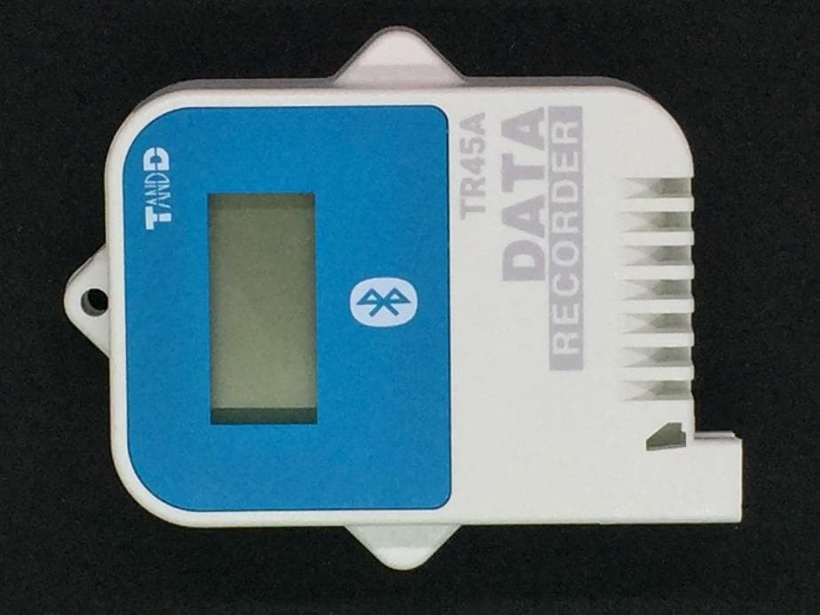
SRD50150
Sep 26, 2024Data Logger
Equipment Class
DTS - Digital Transmission System
SRD50140
Apr 08, 2023Data Logger
Equipment Class
DTS - Digital Transmission System
SRD50110
Jul 11, 2021Data Logger
Equipment Class
DTS - Digital Transmission System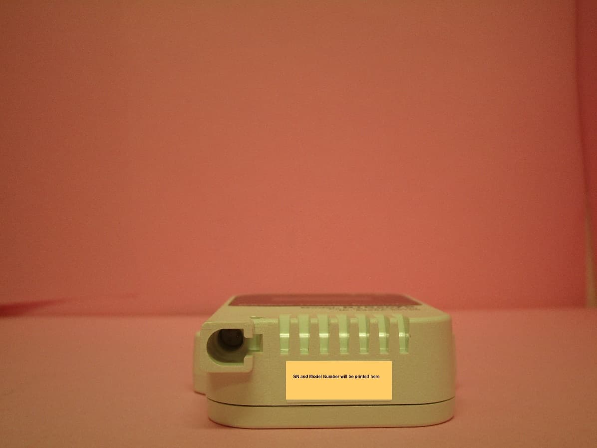
SRD50100
Dec 02, 2020Data Logger Remote Unit
Equipment Class
DTS - Digital Transmission System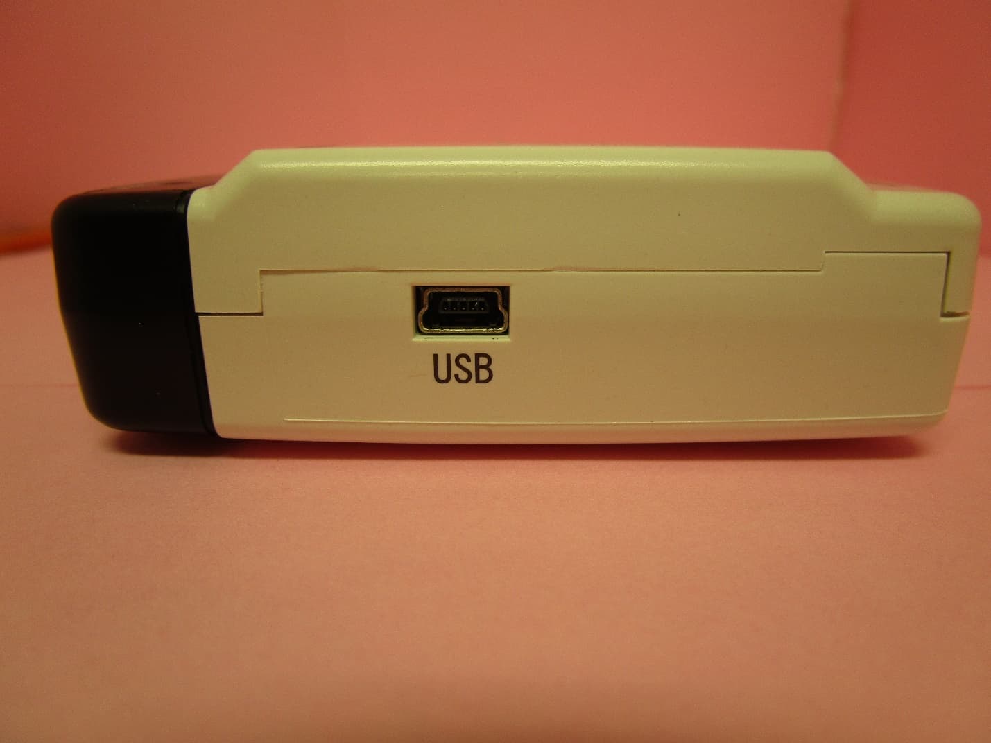
SRD10100
Dec 02, 2020Data Logger Base Unit
Equipment Class
DTS - Digital Transmission System