SRD50060Wireless LAN Thermo Recorder
TandD Corporation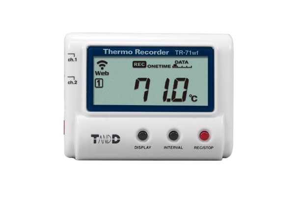
Click to zoom
Application Details
- Equipment Class
- DTS - Digital Transmission System
- Date of Grant
- Sep 30, 2013
- Application Purpose
- Original Equipment
- Date of Application
- Sep 29, 2013
- Equipment Note
- Wireless LAN Thermo Recorder
- Frequency Range
- 2412.00000000 - 2462.00000000
- Company
- TandD Corporation
- Country
- Japan
Documents & Files
Document Text
Text extracted from the exhibit documents filed with the FCC. Open a document above to read the original.
Users Manual
Please Read First TR-71wf TR-72wf TR-72wf-H Part Names and Functions [RIGHT SIDE][FRONT] [BACK] [LEFT SIDE] Sensor Jack Channel 1 For connecting a sensorINTERVAL ButtonPress to change recording/upload interval settings or view current settings. Sensor Jack Channel 2 For connecting a sensor (TR-71wf only) REC/STOP ButtonPress to start or stop recording. POWER ButtonUse this to turn the device ON and OFF. USB PortFor connecting to PC with USB cable DISPLAY ButtonPress to change LCD display mode. Battery Cover Safety Precautions and Instructions The following items should be strictly obeyed for the safe usage of this product, and for protecting yourself and other people from bodily harm and/or damage to property. Explanation of Symbols <Warning Symbols> DANGER These entries are actions that absolutely under no circumstance should be taken. The taking of such an action may cause serious personal physical damage or death. CAUTION These entries are actions that if taken may lead to physical injury or damage to persons or things. <Picture Symbols> Denotes an impor- tant warning or caution. Denotes a forbidden action. Denotes an action that should be carried out. DANGER To Prevent Serious Accidents Do not disassemble, repair or modify the unit and accessories. Do not use the unit in any environment that is exposed to chemicals and harmful gases. Doing so may cause corrosion and/or other danger to the unit. Also, coming in contact with hazardous substances may cause bodily harm to the user or people nearby. This unit is not water resistant. If water or a foreign object enters the case, immedi- ately remove batteries and stop using it. Do not handle the unit, remove batteries or cables with wet hands. This product has been designed for private and/or industrial use only. It should not be used in situations where strict safety precautions are necessary such as with medical equipment, or in systems directly or indirectly connected with human life or well-being. Do not drop or expose the unit to a strong impact. Do not connect any communication cables connected to the unit to telephone line outlets. Continued use may cause fire or electrocution. Do not cut or process the cords for the communication cables. Also, do not twist, pull on or swing any of the cords. To prevent damage to the unit from static electricity, remove static electricity from your body by touching metal around you (such as a door knob and window frame) before touching the unit. Place and store the unit and accessories out of the reach of children. We are not responsible for any damage, malfunction or trouble, whether direct or indirect, caused by the use of our product. Do not use any battery, sensor, or cable other than those specified by T&D Corpora- tion. Do not put anything on top of the cable. This may cause overheating. Do not disconnect the USB cable during USB communication. Doing so may cause adverse effects to the unit and/or PC. Make sure that sensor and cable plugs are all inserted fully, so as not to cause an improper connection. Also, when unplugging the cable from the unit, do not pull the cord, but hold the connector to disconnect. If the unit produces heat, emits smoke or a strange smell, or makes unusual noise, immediately remove the batteries and stop using it. Also, unplug the unit from the PC. If the unit is not to be used for a long period of time, remove batteries. If left in the unit, the batteries may leak and lead to malfunctioning. Install new batteries when starting or re-starting to use a unit. CAUTION Do not place or store in the following areas: • Areas exposed to direct sunlight • Areas exposed to excessive heat or high temperatures such as near fire or heating equipment • Areas exposed to static electricity • Areas exposed to strong magnetic fields • Areas exposed to dampness • Areas subject to condensation or wet areas • Areas exposed to excessive vibration • Areas exposed to excessive smoke, dust or dirt. CAUTION Other Precautions • Use the unit in the specified operating environment. Do not use it for any purpose other than for which it was designed. • Condensation may occur inside the case when a unit is moved from one environment to another where there is a great difference in temperature. • Do not use the unit in wet areas or places exposed to water such as bathroom. • When connecting the unit to your PC, make sure to follow all warnings and directions from your com- puter manufacturer. • We shall not guarantee the unit's operation if it has been connected to a PC using a USB hub or a USB extension cable. • Do not insert any foreign objects into any of the units' jacks. • If the unit gets dirty, wipe it with a clean cloth. • Make sure to remove dust and dirt from plugs of any cables. • Battery terminals may provide insufficient contact due to age or vibration. This may lead to data loss. • If the unit is not to be used for a long period of time, for safety reasons please remove the battery. If left in the unit, the battery may leak and lead to malfunctioning. • Please note that this document has been written based on the presupposition that details about con- tracts with an Internet provider, specific network environments and the set-up of any other necessary equipment to enable network connection has already been taken care of by the User and that con- nection has been confirmed as workable. T&D Corporation shall not be responsible for any damages which a contractor, a user or a third party may suffer, whether direct or indirect, due to the inability to communicate or use communication devices. CAUTION Notices about Sensors • Do not connect any sensor to the unit other than those specified by T&D Corporation. • Make sure to use sensors within the measurement range indicated in the specifications for that sensor. • If extremely severe temperature changes occur, it may result in large errors in humidity measure- ment. Once the sensor's temperature becomes stable, the measurements will return to…
Text truncated - open the document above for the full version.
Users Manual
Making Settings By making settings for auto-upload, it is possible to automatically upload recorded data to the online T&D WebStorage Service. • In the auto-upload, the maximum number of readings which can be stored in T&D WebStorage Service is 80,000. When this limit is exceeded, the oldest data will be overwritten and deleted. • Wireless LAN settings via operation of buttons on the logger can be made only when using a wireless LAN access point supporting WPS. • If your access point does not support WPS, use the T&D application "TR-7wf for Windows" or "ThermoWEB" to make wireless LAN settings. Make sure you have your Wireless LAN SSID, Security Mode, and Security Key (Password) information. • The time difference setting can be changed via TR-7wf for Windows or ThermoWEB. The default time difference is as follows: Serial number "No.4XXXXXXX" : GMT +1:00 Serial number "No.3XXXXXXX" : GMT -8:00 11 Press-and-hold the <POWER> and <DISPLAY> buttons together until appears on the LCD screen. 21 Set your wireless LAN access point to "WPS" mode. For details on the wireless LAN access point, contact the manufacturer of your access point. 31 If the setup is successfully completed, the mark on the LCD display will turn ON. If keeps blinking: It means the device is unable to connect to the wireless network. After adjusting the distance between the device and the access point, start from step 1 again. 41 Click the <INTERVAL> button to display the current upload interval. 51 Press-and-hold the <INTERVAL> button until the display flashes. 61 With each pressing of the <INTERVAL> button the upload inter- val time will change. When the desired interval appears, stop pressing the button. If you wish NOT to use the auto-upload feature, select "OFF". Below are some examples of upload intervals and the corresponding estimated battery life1 In general, the shorter the upload interval, the shorter the battery life. Upload Interval1 min.10 min.1 hr.12 hrs. Battery LifeAbout 10 daysAbout 2 monthsAbout 1 yearAbout 1.5 years * All estimates are based on operations carried out with a new battery and are in no way a guarantee of actual battery life. * The auto-upload interval can also be changed during a recording session. Installing the Device Install the device to the actual place it will be used. To perform auto-upload, make sure to install the device at a place that has wireless LAN Internet access. Check Wireless LAN Connection Status InternetWireless LAN Access Point Checking Connection Status By pressing the <REC/STOP> button, recorded data will be sent to T&D WebStorage Service. If the transmission is successful, will still be ON even after communication is complete and turns OFF. is blinking : Wireless LAN connection failed. Try adjusting the position of the device or its distance from the access point. is blinking : Internet connection failed. Confirm whether your access point can connect to the Internet. Checking Recorded Data Check recorded data uploaded to the T&D WebStorage Service. 11 Access T&D WebStorage Service from the web browser on your PC or mobile device. T&D WebStorage Service : http://www.webstorage-service.com/ 21 Follow the directions as they appear to get a User ID. If you already have your User ID, go to 3 below. 31 Login by entering the registered User ID and Password. 41 Clicking the [Account] button will take you to the Account Man- agement page. 51 Select [Device Registration], and enter the serial number and registration code for the target TR-7wf Series and then click the [Register this device] button. The registration code can be found on the supplied Registration Code Label. 61 At first, only the added TR-7wf Series device will appear in the [Current Readings] tab page. Measurements will appear after clicking the <REC/STOP> button on the device or when data is auto-uploaded from the device. If measurements are not displayed: * Check the device screen to make sure is ON. Recorded data will not be uploaded when recording is not in progress. * See "Checking Connection Status" in , and check if the device has a wireless LAN connection. If the display of measurements is not refreshed: We recommend making the recording interval shorter than the auto-upload interval. If the recording interval is set to longer than the upload interval, the same measurement is displayed until the next recording occurs and the new data is uploaded. View Data from other than a Web Browser Recorded data which was sent to the T&D WebStorage Service can also be viewed with ThermoWEB and/or T&D Graph. Saving Auto-Uploaded Data Recorded data which has been uploaded to the T&D WebStorage Service can be saved in the PC by using T&D Graph and accessing T&D WebStorage Service. For details, please see printed on the back of this paper. Changing the Settings By using the T&D WebStorage Service, it is possible to change the following settings: • Auto-upload Interval• Warning Settings The changes in settings will be applied when the device communicates with the T&D WebStorage Service. To apply the changes immediately, press the <REC/STOP> button on the device after settings are completed. Thermo Recorder TR-7wf Series Introductory Manual What can TR-7wf Series devices do? Auto-upload of Recorded Data *1 Wireless LAN Communication View with a Web Browser Setup and Data Download Setup and Data Download Graph Display Graph Display Setup USB Communication *2 Smartphone Tablet device PC TR-7wf Series TR-7wf SeriesTR-7wf Series Graph Display Download Data Wireless Communication *3 (Wireless LAN) Apply Settings Via Cloud Via USBVia Wireless *1: To auto upload recorded data to the T&D WebStorage Service, it is necessary to have Internet access via wireless LAN and a T&D WebStorage Service User ID. *2: A USB communication cable (sold separately) is required for connecting the TR-7wf series device to your computer. *3: A mobile device with wireless LAN capability is required for direct communication with the TR-7wf series device. S…
Text truncated - open the document above for the full version.
Users Manual
Regarding the Use of Wireless LAN Products 16704930002 (1st Edition) http://www.tandd.com/ Precautions when Installing Wireless Communication Devices Wireless LAN signals are affected by device placement and interference caused by other environmental factors. The following factors can especially cause an unstable wireless connection, please be mindful of them when deploying devices. Physical Objects: Placing the unit far from a wireless LAN access point and/or near to obstacles (such as metal objects, concrete, plants, etc.) may lead to a poor wireless connection. Electrical Interference: Placed near cooking equipment such as microwave ovens or communication devices that generate electromagnetic waves. Access Point Capacity: Having many devices connected to one access point simultaneously. Regar ding how many wireless devices can simultaneously connect to an access point and still maintain stable connections, please contact the manufacturer of the wireless access point. Channel Congestion: Using multiple wireless LAN access points with the same communication frequency channel. Change the wireless LAN access point settings to assign a non-over- lapping channel to each access point. Note: If unstable wireless connection continues, not only will more data transmission errors occur, but battery life will also be shortened. Compliance Information For FCC Model FCC and IC Statement This device complies with Part 15 of the Federal Communications Commission (FCC) rules and RSS-210 of the Industry Canada (IC). Operation is subject to the following two conditions: (1) This device may not cause harmful interference, and (2) this device must accept any interference received, including interference that may cause undesired operation. Ce dispositif est conforme à la norme RSS 210 d’Industrie Canada. L’utilisation de ce dispositif est autorisée seulement aux conditions suivantes : (1) il ne doit pas produire de brouillage et (2) l’utilisateur du dispositif doit être prêt à accepter tout brouillage radioélectrique reçu, même si ce brouillage est susceptible de compromettre le fonctionnement du dispositif. This equipment has been tested and found to comply with the limits for a Class B digital device, pursuant to Part 15 of the FCC Rules. These limits are designed to provide reasonable protection against harmful interference in a residential installation. This equipment generates, uses and can radiate radio frequency energy and, if not installed and used in accordance with the instructions, may cause harmful interference to radio communi- cations. However, there is no guarantee that interference will not occur in a particular installation. If this equipment does cause harmful interference to radio or television reception, which can be determined by turning the equipment off and on, the user is encouraged to try to correct the interfer- ence by one or more of the following measures: - Reorient or relocate the receiving antenna. - Increase the separation between the equipment and receiver. - Connect the equipment into an outlet on a circuit different from that to which the receiver is connected. - Consult the dealer or an experienced radio/TV technician for help. Continued on Back Page. To comply with the limits for the Class B digital device, pursuant to Part 15 of the FCC Rules, this device must be installed in computer equipment All cables used to connect the computer and peripherals must be shielded and gr cables may result in interference to radio or television reception. Caution: This Class B digital apparatus complies with Canadian ICES-003. Cet appareil numérique de la classe B est conforme à la norme NMB-003 du Canada. This transmitter must not be co-located or operated in conjunction with any other antenna or transmitter. For CE Model CE Statement Important Notice Wireless products cannot be used in countries other than where those products have been approved for use, according to that country's wireless regulations. T&D Corporation shall in no manner whatsoever take responsibility for the usage of these products, nor be liable in any manner for legal conse- quences stemming from the usage of these wireless products in unapproved areas. • • LAN TR-7wfLAN 1. 2. 3. http://www.tandd.co.jp/support/ 2.4 2.4GHz DS DS-SS 4 40m This equipment complies with FCC/IC radiation exposure limits set forth for an uncontrolled environment and meets the FCC radio frequency (RF) Exposure Guidelines and RSS-102 of the IC radio frequency (RF) Exposure rules. This equipment has very low levels of RF energy that it deemed to comply without maximum permissive exposure evaluation (MPE). But it is desirable that it should be installed and operated keeping the radiator at least 20cm or more away from person’s body (excluding extremities: hands, wrists, feet and ankles). Cet équipement est conforme aux limites d’exposition aux rayonnements énoncées pour un environnement non contrôlé et respecte les règles les radioélectriques (RF) de la FCC lignes directrices d'exposition et d’exposition aux fréquences radioélectriques (RF) CNR-102 de l’IC. Cet équipement émet une énergie RF très faible qui est considérée conforme sans évaluation de l’exposition maximale autorisée. Cependant, cet équipement doit être installé et utilisé en gardant une distance de 20 cm ou plus entre le dispositif rayonnant et le corps (à l’exception des extrémités : mains, poignets, pieds et chevilles).
External Photos
External Photo [Model: TR-71wf] Front Rear External Photo [Model: TR-71wf] Top Bottom External Photo [Model: TR-71wf] Right Left
External Photos
External Photo [Model: TR-72wf] Front Rear External Photo [Model: TR-72wf] Top Bottom External Photo [Model: TR-72wf] Right Left
ID Label/Location Info
25 20 R0.2 (4ヶ所) 認証No. 量産時には正しい認可番号を表示する φ5.5 ・材質:PET 50μ ベース色:白 ・文字色:黒 ・表面はラミネート処理 ・版下No.852-0493-1090 坂野 坂野13.09.04 TR-7wf(US) 認証シール 162-0493-0040 二木 設計 製図 検図 承認 内 容 年 月 日 担当 株式会社 ティアンドデイ 材料 処理 品名 製品コード 0 0.5 0.5 6 6 30 30 120 120 350 350 1000 ±0.05 ±0.1 ±0.2 ±0.3±0.5 ±0.8 1 2 3 差 公 度 尺 位 単 2:1 Doc.No.851-0493-0040US認証 mm
Internal Photos
Internal Photo [Model: TR-71wf] Front with LCD Front Internal Photo [Model: TR-71wf] Rear with Shield Rear
Internal Photos
Internal Photo [Model: TR-72wf] Front with LCD Front Internal Photo [Model: TR-72wf] Rear with Shield Rear
RF Exposure Info
Applicant: Tand D Corporation Type of Equipment : Wireless LAN Thermo Recorder Model No. : TR-71wf / TR-72wf FCC ID: 5558A-50060 Tand D Corporation declares that Model : TR-71wf / TR-72wf ⇒ complies with FCC radiation exposure requirement specified in the FCC Rules A292.1091 (for mobile). RF Exposure Calculations: ← The following information provides the minimum separation distance for the highest gain antenna provided with the “TR-71wf / TR-72wf“ as calculate d from (B) Limits for General Population / Uncontrolled Exposure of TABLE 1- LIMITS FOR MAXIMUM PERMISSIBLE EXPOSURE (MPE) of §1.1310 Radiofrequency radiation exposure limits. This calculation is based on the highest EIRP possible from the system, considering maximum power and antenna gain, and considering a 1.0mW/cm^2 uncontrolled exposure limit. The Friis formula used was: S = (P * G) / (4* π * r 2 ) Where P = 15.45 mW (Maximum peak output power) G = 1.64 Numerical Antenna gain; equal to2.14dBi r =20.0 cm For: TR-71wf / TR-72wfS =0.00503 mW/cm 2 No. : 10007808H RF Exposure / MPE Calculation
Test Report
Test report No. : 10007808H-A-R1 Page : 2 of 31 Issued date : August 30, 2013 Revised date : September 27, 2013 FCC ID : SRD50060 UL Japan, Inc. Head Office EMC Lab. 4383-326 Asama-cho, Ise-shi, Mie-ken 516-0021 JAPAN Telephone : +81 596 24 8999 Facsimile : +81 596 24 8124 REVISION HISTORY Original Test Report No.: 10007808H-A Revision Test report No. Date Page revised Contents - (Original) 10007808H-A August 30, 2013 - - 1 10007808H-A-R1 September 27, 2013 P.11 Correction of KDB Section number Test report No. : 10007808H-A-R1 Page : 3 of 31 Issued date : August 30, 2013 Revised date : September 27, 2013 FCC ID : SRD50060 UL Japan, Inc. Head Office EMC Lab. 4383-326 Asama-cho, Ise-shi, Mie-ken 516-0021 JAPAN Telephone : +81 596 24 8999 Facsimile : +81 596 24 8124 CONTENTS PAGE SECTION 1: Customer information ......................................................................................................... 4 SECTION 2: Equipment under test (E.U.T.) ........................................................................................... 4 SECTION 3: Test specification, procedures & results ............................................................................ 5 SECTION 4: Operation of E.U.T. during testing .................................................................................... 8 SECTION 5: Conducted Emission .......................................................................................................... 10 SECTION 6: Radiated Spurious Emission ............................................................................................ 11 SECTION 7: Antenna Terminal Conducted Tests ................................................................................ 12 APPENDIX 1: Data of EMI test .............................................................................................................. 13 Conducted Emission ......................................................................................................................... 13 6dB Bandwidth ................................................................................................................................. 16 Maximum Peak Output Power .......................................................................................................... 18 Radiated Spurious Emission ............................................................................................................. 19 Conducted Spurious Emission .......................................................................................................... 23 Power Density ................................................................................................................................... 26 99%Occupied Bandwidth ................................................................................................................. 28 APPENDIX 2: Test instruments ............................................................................................................. 29 APPENDIX 3: Photographs of test setup ............................................................................................... 30 Conducted Emission ......................................................................................................................... 30 Radiated Spurious Emission ............................................................................................................. 31 Worst Case Position (Horizontal: X-axis/ Vertical:Y-axis) .............................................................. 32 Test report No. : 10007808H-A-R1 Page : 4 of 31 Issued date : August 30, 2013 Revised date : September 27, 2013 FCC ID : SRD50060 UL Japan, Inc. Head Office EMC Lab. 4383-326 Asama-cho, Ise-shi, Mie-ken 516-0021 JAPAN Telephone : +81 596 24 8999 Facsimile : +81 596 24 8124 SECTION 1: Customer information Company Name : TandD Corporation Address : 817-1 Shimadachi, Matsumoto, Nagano 390-0852 JAPAN Telephone Number : +81-263-40-0027 Facsimile Number : +81-263-40-3152 Contact Person : Masaya Futatsugi SECTION 2: Equipment under test (E.U.T.) 2.1 Identification of E.U.T. Type of Equipment : Wireless LAN Thermo Recorder Model No. : TR-71wf / TR-72wf Serial No. : Refer to Section 4, Clause 4.2 Rating : DC 5.0V (USB) DC 3.0V (Battery) Receipt Date of Sample : August 11, 2013 Country of Mass-production : Japan Condition of EUT : Production prototype (Not for Sale: This sample is equivalent to mass-produced items.) Modification of EUT : No Modification by the test lab 2.2 Product Description General Specification Clock frequency(ies) in the system : CPU: 16MHz, WLAN CPU44MHz Radio Specification Radio Type : Transceiver Frequency of Operation : 2412-2462MHz Modulation : DSSS Power Supply (radio part input) : DC 1.8V Antenna type : PCB Pattern Antenna Antenna Gain : 2.14dBi (Max) *Model No. TR-71wf has a similar model: TR-72wf. The difference between TR-71wf and TR-72wf is only sensor. (Same radio module is embedded in these models) The test was performed with TR-71wf as a representative because it has the worst result. Test report No. : 10007808H-A-R1 Page : 5 of 31 Issued date : August 30, 2013 Revised date : September 27, 2013 FCC ID : SRD50060 UL Japan, Inc. Head Office EMC Lab. 4383-326 Asama-cho, Ise-shi, Mie-ken 516-0021 JAPAN Telephone : +81 596 24 8999 Facsimile : +81 596 24 8124 SECTION 3: Test specification, procedures & results 3.1 Test Specification Test Specification : FCC Part 15 Subpart C: 2013, final revised on June 11, 2013 and effective July 11, 2013 Title : FCC 47CFR Part15 Radio Frequency Device Subpart C Intentional Radiators Section 15.207 Conducted limits Section 15.247 Operation within the bands 902-928MHz, 2400-2483.5MHz, and 5725-5850MHz * The EUT complies with FCC Part 15 Subpart B: 2013, final revised on June 11, 2013 and effective July 11, 2013. 3.2 Procedures and results Item Test Procedure Specification Worst margin Results Remarks Conducted Emission FCC: ANSI C63.4:2003 7. AC powerli…
Text truncated - open the document above for the full version.
Test Setup Photos
Test report No. : 10007808H-A-R1 Page : 30 of 31 Issued date : August 30, 2013 Revised date : September 27, 2013 FCC ID : SRD50060 UL Japan, Inc. Head Office EMC Lab. 4383-326 Asama-cho, Ise-shi, Mie-ken 516-0021 JAPAN Telephone : +81 596 24 8999 Facsimile : +81 596 24 8124 APPENDIX 3: Photographs of test setup Conducted Emission Photo 1 Photo 2 Test report No. : 10007808H-A-R1 Page : 31 of 31 Issued date : August 30, 2013 Revised date : September 27, 2013 FCC ID : SRD50060 UL Japan, Inc. Head Office EMC Lab. 4383-326 Asama-cho, Ise-shi, Mie-ken 516-0021 JAPAN Telephone : +81 596 24 8999 Facsimile : +81 596 24 8124 Radiated Spurious Emission Photo 1 Photo 2
Contact Information
Applicant
Ryota Suzuki(Corporate Director)
Technical Contact
UL Japan, Inc.Masanori Nishiyama
[email protected]81-596-24-8999
4383-326 Asama-cho, Ise-shi · Mie-ken · Japan
Test Firm
UL Japan, Inc. Head office EMC Lab.Tetsuya Hashimoto
Technical Specifications
| # | Rule Parts | Frequency Range | Power Output |
|---|---|---|---|
| 1 | 15C | 2.41 GHz - 2.46 GHz | 15.50 mW |
Other Applications from TandD Corporation
SRD50150
Sep 26, 2024Data Logger
Equipment Class
DTS - Digital Transmission System
SRD50140
Apr 08, 2023Data Logger
Equipment Class
DTS - Digital Transmission System
SRD50110
Jul 11, 2021Data Logger
Equipment Class
DTS - Digital Transmission System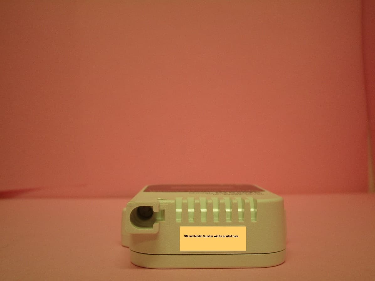
SRD50100
Dec 02, 2020Data Logger Remote Unit
Equipment Class
DTS - Digital Transmission System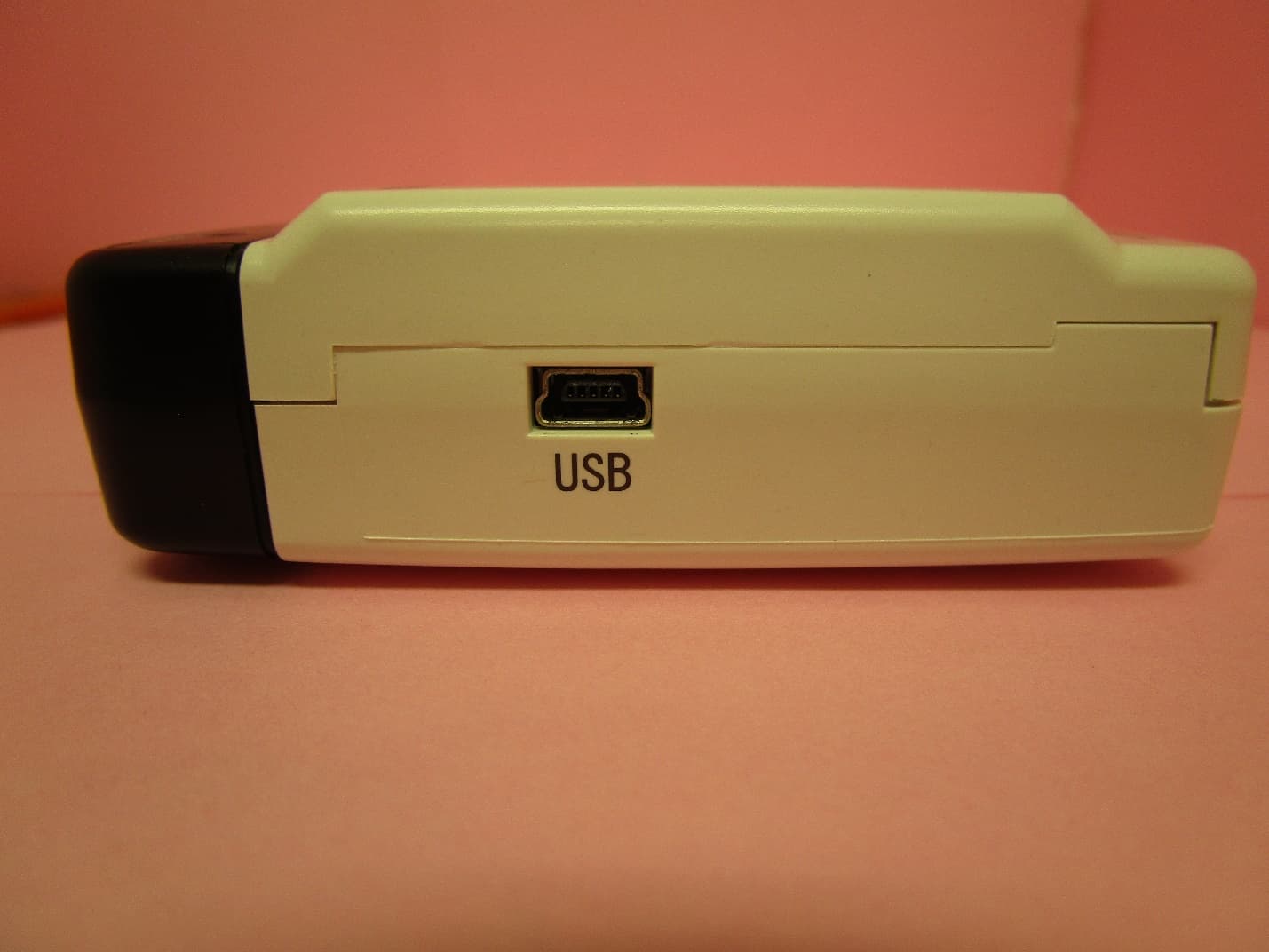
SRD10100
Dec 02, 2020Data Logger Base Unit
Equipment Class
DTS - Digital Transmission System