SRDRTR5X900 MHz Data Recorder
TandD Corporation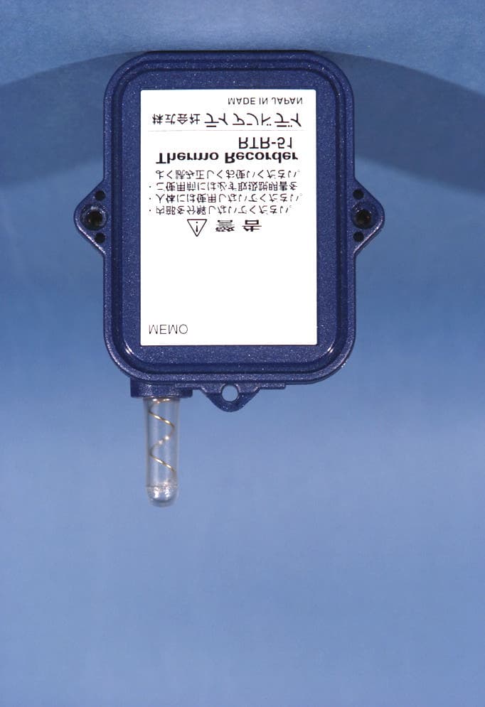
Click to zoom
Application Details
- Equipment Class
- DXT - Part 15 Low Power Transceiver, Rx Verified
- Date of Grant
- Dec 28, 2004
- Application Purpose
- Original Equipment
- Date of Application
- Dec 28, 2004
- Equipment Note
- 900 MHz Data Recorder
- Frequency Range
- 902.28000000 - 927.64000000
- Company
- TandD Corporation
- Country
- Japan
Documents & Files
Document Text
Text extracted from the exhibit documents filed with the FCC. Open a document above to read the original.
Users Manual
2003.07 16004264080 User’s Manual Thank you for purchasing our product. Carefully read this instruction manual before using this unit. ��������� ��������� ��� ������������ ��� ������ ��������� ■ Notices about this User’s Manual Carefully read this manual so that you can properly use this product. T&D Corporation accepts no responsibility for any malfunction of and / or trouble with this product or with your computer that is caused by the improper handling of this product and will deem such trouble or malfunction as falling outside the conditions for free repair of the attached warranty. ● All rights of this user’s manual belong to T&D Corporation. It is prohibited to use, duplicate and / or arrange a part or whole of this user’s manual without the permission of T&D Corporation. ● Microsoft and Windows are registered trademarks of Microsoft Corporation USA and are binding in the USA and all other countries. ● Company names and product names are trademarks or registered trademarks of each company. ● Specifications, design and other contents are subject to change without notice. ● On screen messages in this manual may vary slightly from the actual messages. ● Please notify the shop where you purchased this product or T&D Corporation of any mistakes, errors or unclear explanations in this manual. T&D Corporation accepts no responsibility for any damage or loss of income caused by the use of our product. ● This product has been designed for private or industrial use only. It is not for use in situations where strict safety precautions are necessary such as in connection with medical equipment, whether directly or indirectly. ● We are not responsible for any malfunction or trouble caused by the use of our product or by any problem caused by the use of measurement results of our unit. Please be fully aware of this before using our product. ● Some of our products, which come under the category of strategic goods in foreign trade law, need the permission of the Japanese government to be exported outside of Japan. ● This user’s manual cannot be reissued, so please keep it in a safe place. ● Please carefully read warranty and provisions for free repair. i ■ Escape Clauses ● T&D Corporation does not guarantee the operation of T&D Recorder for Windows. ● T&D Corporation shall not accept any responsibility for any damage, whether direct or indirect, that results from the usage of T&D Recorder for Windows. ● Specifications of T&D Recorder for Windows may be subject to change and service may be terminated without advance notice to the user. In such a case, T&D Corporation shall not be responsible for any damages, whether direct or indirect, from the inability to use T&D Recorder for Windows. ● T&D Corporation has no obligation to correct any defects found in T&D Recorder for Windows. ■ Copyright ● The Copyright for T&D Recorder for Windows, including the program and relevant documents, belongs solely to T&D Corporation. ● The reprinting or redistribution for commercial purposes whether in part or in whole, in magazines or as a part of any product is strictly forbidden without the expressed consent of T&D Corporation. Any inquires concerning commercial redistribution should be directed to the Sales Department of T&D Corporation. ● Please do not attempt to make any changes or modifications to T&D Recorder for Windows. Software User Agreement ii iii Table of Contents Introduction ● Software User’s Agreement ...................ii ● What is T&D Recorder for Windows ?........1 ● Communication with Data Loggers ............3 Getting Ready ● Installing the Software .......................5 ● Operating the Software ......................6 ● Computer Communication Settings ・ Connecting the Communication Cable .......8 ・ Setting Up the Serial Port ..................9 ● Remote Unit Registration .....................11 ・ Other Remote Unit Registration Functions ....16 Basic Functions ● RTR-51 / 52 ・ Start Recording ...........................21 ・ Downloading Recorded Data ...............23 ● RTR-53 ・ Start Recording ...........................25 ・ Downloading Recorded Data ...............28 ● RVR-52 ・ Start Recording ...........................29 ・ Downloading Recorded Data ...............32 ● RTR-57C ・ Downloading Recorded Data ...............33 ・ Set Clock ................................39 ・ Set Upper and Lower Limits ................40 iv Temperature and Humidity Graph ● Display Names and Functions ................41 ● Editing the Graph ・ Changing the Graph Display ................45 ・ Graph Operation ..........................50 Multi-Scale Graph ● Display Names and Functions ................51 ● Editing the Graph ・ Changing the Graph Display ................55 ・ Graph Operation ..........................62 Event Viewer ● Display Names and Functions ................63 ● File Information .............................65 ● Printing Preview and Printing .................66 Other Functions ● Saving Recorded Data .......................67 ● Creating Text File ...........................69 ● Opening Data Files ..........................71 ● Re-installation ..............................72 Other ● Troubleshooting .............................73 ● Specifications ...............................77 1 ■ Outline By using T&D Recorder for Windows, you can easily display the data measured and recorded with the RTR-51/52/53, RVR-52 via our exclusive short-wave wireless technology in table or graph form and control printing with your computer. Upon opening T&D Recorder for Windows, a launcher window in which icons are displayed will appear. By clicking an icon, the graph, settings, and /or communication screen for that type of unit will be displayed. This software requires the following operating environment: Compatible OS Microsoft Windows 98 / Me / NT 4.0 Microsoft Windows 2000 / XP PC / CPU IBM compatible equipped with more than Pentium 90MHz or NEC 98 Series with serial communication (RS-232C D-Sub 9 pin). Memory More than16…
Text truncated - open the document above for the full version.
Users Manual
40 RTR-57C Upper and Lower Limits RTR-57C Upper and Lower Limits can be set from your computer. Setting is directly possible in RTR-57C Main Units version 2 or higher. The version can be confirmed in [Help]-[RTR-57C Version Info]. See the Help Menu in T&D Recorder for Windows for details. 1. In the main window, click the icon RTR-57C. 2. Click the [Upper and Lower Limit Settings] tab, and check the < Change > box. 3.After entering the upper and lower limit values, check <ON> and by clicking the [Write] button, the information will be transmitted. ON: Judges whether recorded data is within the set range when RTR-57C has downloaded the recorded data. OFF: Judgment isn’t carried out even if upper and lower limits have been set. 4.Click [Close] button to complete the setting. ■ [ Read ] Button If you wish to view the current settings, click the [Read] button. [ Write ] button Enter upper and lower limit values. Check ON/OFF Check < Change > [Upper and Lower Limit Settings] tab [ Close ] button [ Read ] button ■ Display Names and Functions 41 Click Temperature / Humidity Graph ■ How to Open Open the Graph display by clicking the icon [Temp/Humid Graph] in the Main Window. ● In the Main Window or in the Settings/Communication Display of RTR-57C, RTR-51/52, or RTR-53, select the [Temp/Humid Graph] from the [Start] menu to open the graph. ● If you have clicked [Display the graph after downloading recorded data], the graph will automatically open. ② ⑥⑤ ① ③ ④ ⑦ ⑧ ⑨ ⑩ ④ Menu Bar Click on the desired menu in the Menu Bar to set or display each function from which you can choose from an array of commands. ⑤ Button for Moving Horizontal Axis The time axis moves by clicking these arrow buttons. ⑥ Horizontal Gauge Bar By dragging the gauge you can move left and right to the data you want to be displayed. ⑦ Button for Moving Vertical Axis The vertical axis moves up or down by clicking these arrow buttons. ⑧ Vertical Gauge Bar By dragging the gauge you can move up and down to the data you want to be displayed. ⑨ A and B Cursor Position Information ⑩ Channel Info List Display Displays data information for Channels 1 to 8. ① A and B Cursor Movement Buttons By clicking the arrow buttons, you can simultaneously move the A/B cursors. ② A and B Cursor Buttons Click and drag the A or B button to move the cursor to the left or right. ③ Toolbar Buttons appear for frequently used commands. 42 ① Open File ② Overwrite Data ③ Save Data as... ④ Change Data Display Colors ⑤ Data Display ON/OFF ⑥ Return to Original Size ⑦ Step-by-Step to Original ⑧ Set High, Low, Avg. Calculation Range ⑨ Edit Recording Conditions ⑩ Re-order Channels ⑪ Erase Selected Channels Data ⑫ Vertical Axis Settings ⑬ Print ⑭ Help ⑮ Hide / View Channels ②⑤⑦⑫ ①③⑥④⑪⑧⑨⑩⑬ ⑮ ⑭ 43 ● Zoom in Using the Mouse With the left button drag the mouse to outline the area you want to zoom in on. ● Menu Display Using the Mouse By right clicking on the graph, the Menu will be displayed. 44 ■ Data List Display ● [Date / Time] Button By clicking this button, you can shift the display between the recorded date and amount of elapsed time since recording started. ① This is a list of the data that was displayed in graph form. The highest value is in RED, lowest is in BLUE, and the average is in PINK. ② Scroll Bar: By dragging it up and down you can move to the data you want. ① ② Recorded Date Display [ Date / Time ] Button Elapsed Time Display ● Menu Display Using the Mouse By right clicking on the list, the Menu will be displayed. 45 ● Selected Channels ON/OFF: From the [View] Menu 1.The channel numbers are displayed in the pull down menu of [Selected Channels ON/OFF]. 2.Check the channel numbers you wish to display. ※ By clicking a Channel Number in the Toolbar, you can carry out the same operation. Check 《 Enlarged 》 Editing the Graph ■ Changing the Graph Display ● Changing graph display colors: From the [View] Menu You can change the letters used in the data list display for each channel between monochrome and channel color ● Set High, Low, Average Calculation Range: From the [Tools] Menu 1.Set the calculation range in [Set High, Low, Avg. Calculation Range] box. [OK] button [ Entire Graph ] button Enter the numerical value. 46 2.By clicking the [OK] button, the high, low, average calculation range of each channel data will be changed. On the graph display, the calculation range that you have set will be displayed. 2.By clicking the [OK] button after changing, the setting will be completed. ● If you wish to continue to change other channels, repeat the process as in 1. ※ The [Restore] button is effective only during the setting, and cannot return to the condition it was after the [OK] button has been clicked. ● Name: Up to 32 letters can be entered. ● Starting Date/Time: The month, day, year, hour, minute and second can be changed. ● [ Entire Graph ] Button To make the Calculation Range that of the Entire Graph, click the "Entire Graph" button. The dates and times in the [Set High, Low, Avg. Calculation Range] box will be displayed as those of the entire graph. ● Set by using the AB Cursors In the Graph Display, open the [Set High, Low, Average Calculation Range] box adjusting the AB cursors to the desired start and end positions. The dates and times of those cursors will be displayed automatically. ● Edit Recording Conditions: From the [Tools] Menu 1.By clicking the [Ch.] button you wish to change, the information for that number will be displayed in the "Edit Items". [ Restore ] button [ OK ] button The selected channel number Channel Number Enter letters and numerical values 47 【 Move by selecting the channel number 】 1. Enter in From: , the Channel number you wish to move from, and enter the Channel number to which you want to move in To: . 2. By clicking the [Re-order] button, the movement will be completed. ※ The [Restore] button is effective only during the setting, and cannot return to the condition it was by clicking the [OK] button. 【 Move by dragging the chan…
Text truncated - open the document above for the full version.
External Photos
TandD FCC ID: SRDRTR5X EUT Photographs © 2004 PCTEST Lab. 900 MHz Data Recorder Models: RTR-51, RTR-52 TandD FCC ID: SRDRTR5X EUT Photographs © 2004 PCTEST Lab. 900 MHz Data Recorder Models: RTR-51, RTR-52 TandD FCC ID: SRDRTR5X EUT Photographs © 2004 PCTEST Lab. 900 MHz Data Recorder Models: RTR-51, RTR-52 TandD FCC ID: SRDRTR5X EUT Photographs © 2004 PCTEST Lab. 900 MHz Data Recorder Models: RTR-51, RTR-52 TandD FCC ID: SRDRTR5X EUT Photographs © 2004 PCTEST Lab. 900 MHz Data Recorder Models: RTR-51, RTR-52 TandD FCC ID: SRDRTR5X EUT Photographs © 2004 PCTEST Lab. 900 MHz Data Recorder Models: RTR-51, RTR-52 TandD FCC ID: SRDRTR5X EUT Photographs © 2004 PCTEST Lab. 900 MHz Data Recorder Models: RTR-51, RTR-52 TandD FCC ID: SRDRTR5X EUT Photographs © 2004 PCTEST Lab. 900 MHz Data Recorder Models: RTR-51, RTR-52 TandD FCC ID: SRDRTR5X EUT Photographs © 2004 PCTEST Lab. 900 MHz Data Recorder Models: RTR-51, RTR-52
ID Label/Location Info
Low Power Transceiver, Rx Verified (DXT), FCC Rule Part 15.249 PCTEST LAB TEST REPORT 15.249 FCC CERTIFICATION REPORT Reviewed by: Quality Manager Filename: TX.241117643-R1.SRD Test Dates: Nov. 17-18, 2004 EUT Type: 900 MHz Data Recorder FCC ID: SRDRTR5X Page 17 of 24 © 2004 PCTEST Engineering Laboratory, Inc. CONFIDENTIAL PROPERTY OF PCTEST EXHIBIT B – Labeling Requirements Sample Label & Location New Labeling Requirements Per 2.1074 & 15.19; Docket 95-19 The sample label shown below shall be permanently affixed at a conspicuous location on the device; instruction manual or pamphlet supplied to the user and be readily visible to the purchaser at the time of purchase. However, when the device is so small wherein placement of the label with specified statement is not practical, only the trade name, FCC ID, and the FCC logo must be displayed on the device per Section 15.19 (b)(2). Low Power Transceiver, Rx Verified (DXT), FCC Rule Part 15.249 PCTEST LAB TEST REPORT 15.249 FCC CERTIFICATION REPORT Reviewed by: Quality Manager Filename: TX.241117643-R1.SRD Test Dates: Nov. 17-18, 2004 EUT Type: 900 MHz Data Recorder FCC ID: SRDRTR5X Page 18 of 24 © 2004 PCTEST Engineering Laboratory, Inc. CONFIDENTIAL PROPERTY OF PCTEST EXHIBIT B – Labeling Requirements (Cont.) Sample Label & Location FCC ID Label
Internal Photos
TandD FCC ID: SRDRTR5X EUT Photographs © 2004 PCTEST Lab. 900 MHz Data Recorder Models: RTR-51, RTR-52 TandD FCC ID: SRDRTR5X EUT Photographs © 2004 PCTEST Lab. 900 MHz Data Recorder Models: RTR-51, RTR-52 TandD FCC ID: SRDRTR5X EUT Photographs © 2004 PCTEST Lab. 900 MHz Data Recorder Models: RTR-51, RTR-52 TandD FCC ID: SRDRTR5X EUT Photographs © 2004 PCTEST Lab. 900 MHz Data Recorder Models: RTR-51, RTR-52 TandD FCC ID: SRDRTR5X EUT Photographs © 2004 PCTEST Lab. 900 MHz Data Recorder Models: RTR-51, RTR-52 TandD FCC ID: SRDRTR5X EUT Photographs © 2004 PCTEST Lab. 900 MHz Data Recorder Models: RTR-51, RTR-52 TandD FCC ID: SRDRTR5X EUT Photographs © 2004 PCTEST Lab. 900 MHz Data Recorder Models: RTR-51, RTR-52 TandD FCC ID: SRDRTR5X EUT Photographs © 2004 PCTEST Lab. 900 MHz Data Recorder Models: RTR-51, RTR-52 TandD FCC ID: SRDRTR5X EUT Photographs © 2004 PCTEST Lab. 900 MHz Data Recorder Models: RTR-51, RTR-52
Test Report
© 2004 PCTEST Engineering Laboratory, Inc. PCTEST ENGINEERING LABORATORY, INC. 6660 – B Dobbin Road • Columbia, MD 21045 • USA Telephone 410.290.6652 / Fax 410.290.6654 http://www.pctestlab.com (email: [email protected]) CERTIFICATE OF COMPLIANCE FCC Part 15.249 Certification MANUFACTURER NAME & ADDRESS: DATE & LOCATION OF TESTING: TandD Corporation Date(s) of Tests: November 17-18, 2004 5652-169, Sasaga, Matsumoto City Test Report S/N: TX.241117643-R1.SRD Nagano, 399-0033 JAPAN Test Site: PCTEST Lab, Columbia, MD FCC ID: SRDRTR5X APPLICANT: TandD Corporation SUMMARY: Model No.(s): RTR-51, RTR-52, RTR-53, RVR-521 Equipment EUT Type: 900 MHz Data Recorder Frequency Range: 902.28 – 927.64 MHz FCC Classification: FCC Part 15 Low Power Transceiver, Rx Verified (DXT) FCC Rule Part(s): Parts 15.249 (Subpart C – Intentional Radiator) Test Device Serial No.: S/N: 0 This equipment has been shown to be capable of compliance with the applicable technical standards as indicated in the measurement report and was tested in accordance with the measurement procedures specified in ANSI C-63.4-2001. If the EUT contains any additional embedded transmitters, then those transmitters were active during all tests. All models were evaluated and the worst case data was reported (Model: RTR-52). The JBC portion of this EUT is covered in the DOC report. I authorize and attest to the accuracy of data. All measurements reported herein were performed by me or were made under my supervision and are correct to the best of my knowledge and belief. I assume full responsibility for the completeness of these measurements and vouch for the qualifications of all persons taking them. PCTEST certifies that no party to this application has been denied the FCC benefits pursuant to Section 5301 of the Anti-Drug Abuse Act of 1988, 21 U.S.C. 862. Low Power Transceiver, Rx Verified (DXT), FCC Rule Part 15.249 PCTEST LAB TEST REPORT 15.249 FCC CERTIFICATION REPORT Reviewed by: Quality Manager Filename: TX.241117643-R1.SRD Test Dates: Nov. 17-18, 2004 EUT Type: 900 MHz Data Recorder FCC ID: SRDRTR5X Page i of i © 2004 PCTEST Engineering Laboratory, Inc. CONFIDENTIAL PROPERTY OF PCTEST TABLE OF CONTENTS ATTESTATION STATEMENTS.............................................................................................................................1 FCC PART 15.249 MEASUREMENT REPORT COVER PAGE...........................................................................................2 1.0 INTRODUCTION.......................................................................................................................................................3 1.1 EVALUATION PROCEDURE.......................................................................................................................................................................................................3 1.2 SCOPE................................................................................................................................................................................................................................................3 1.3 PCTEST TEST LOCATION............................................................................................................................................................................................................3 2.0 PRODUCT INFORMATION......................................................................................................................................4 2.1 EQUIPMENT DESCRIPTION........................................................................................................................................................................................................4 2.2 ENCLOSURE....................................................................................................................................................................................................................................4 2.3 EMI SUPPRESSION DEVICE(S)/MODIFICATIONS................................................................................................................................................................4 3.0 DESCRIPTION OF TEST............................................................................................................................................5 3.1 CONDUCTED EMISSIONS..........................................................................................................................................................................................................5 3.2 RADIATED EMISSIONS.................................................................................................................................................................................................................6 4.0 ANTENNA REQUIREMENTS.....................................................................................................................................7 5.0 TEST EQUIPMENT CALIBRATION DATA...............................................................................................................8 EXHIBIT A. SUMMARY.......................................................................................................................................................9 EXHIBIT A. RADIATED FUNDAMENTAL & HARMONIC MEASUREMENTS...................................................................10-12 EXHIBIT A. RADIATED SPURIOUS MEASUREMENTS......................................................................................................13 EXHIBIT A. EQUIPMENT DESCRIPTION...........................................................................................................................14 EXHIBIT A. LINE CONDUCTED.........................................................................................................................................15-16 EXHIBIT B. LABELING REQUIREMENTS.........................................................................…
Text truncated - open the document above for the full version.
Test Setup Photos
TandD FCC ID: SRDRTR5X EUT Photographs © 2004 PCTEST Lab. 900 MHz Data Recorder Models: RTR-51, RTR-52 TandD FCC ID: SRDRTR5X EUT Photographs © 2004 PCTEST Lab. 900 MHz Data Recorder Models: RTR-51, RTR-52 TandD FCC ID: SRDRTR5X EUT Photographs © 2004 PCTEST Lab. 900 MHz Data Recorder Models: RTR-51, RTR-52 TandD FCC ID: SRDRTR5X EUT Photographs © 2004 PCTEST Lab. 900 MHz Data Recorder Models: RTR-51, RTR-52 TandD FCC ID: SRDRTR5X EUT Photographs © 2004 PCTEST Lab. 900 MHz Data Recorder Models: RTR-51, RTR-52 TandD FCC ID: SRDRTR5X EUT Photographs © 2004 PCTEST Lab. 900 MHz Data Recorder Models: RTR-51, RTR-52
Contact Information
Applicant
Ryota Suzuki(Corporate Director)
Technical Contact
PCTEST Engineering Lab., Inc.Randy Ortanez
[email protected]410-290-6652
6660-B Dobbin Road · Columbia, Maryland · United States
Test Firm
PCTEST Engineering Laboratory, Inc.Randy Ortanez
Technical Specifications
| # | Rule Parts | Frequency Range | Power Output |
|---|---|---|---|
| 1 | 15C | 902.28 MHz - 927.64 MHz | - |
Other Applications from TandD Corporation
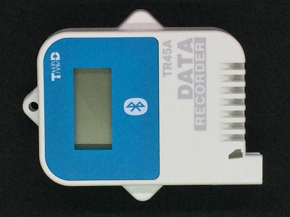
SRD50150
Sep 26, 2024Data Logger
Equipment Class
DTS - Digital Transmission System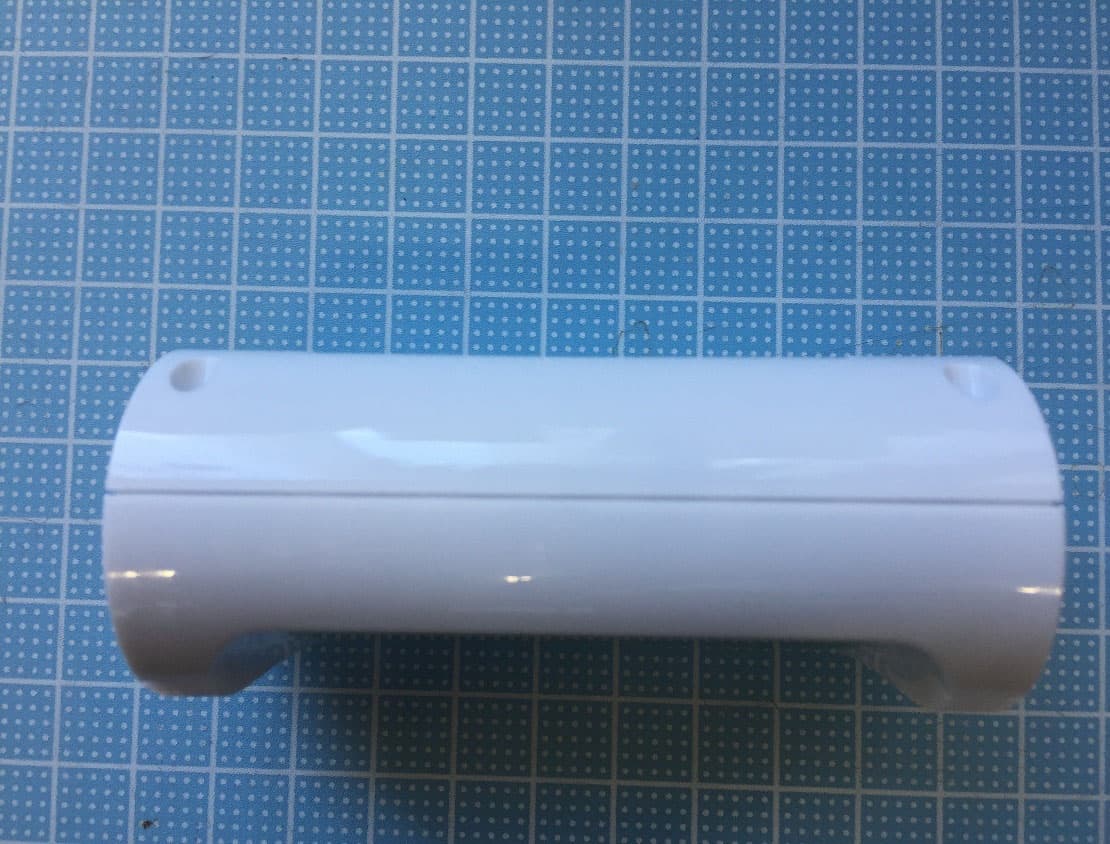
SRD50140
Apr 08, 2023Data Logger
Equipment Class
DTS - Digital Transmission System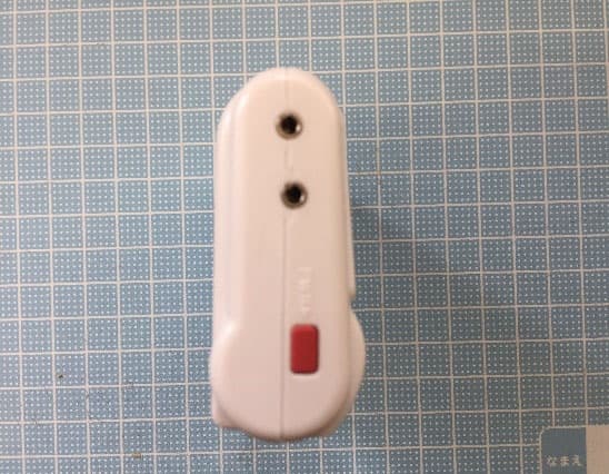
SRD50110
Jul 11, 2021Data Logger
Equipment Class
DTS - Digital Transmission System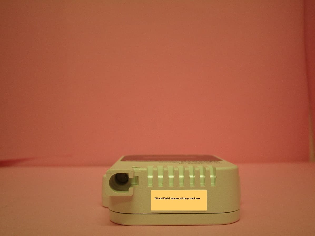
SRD50100
Dec 02, 2020Data Logger Remote Unit
Equipment Class
DTS - Digital Transmission System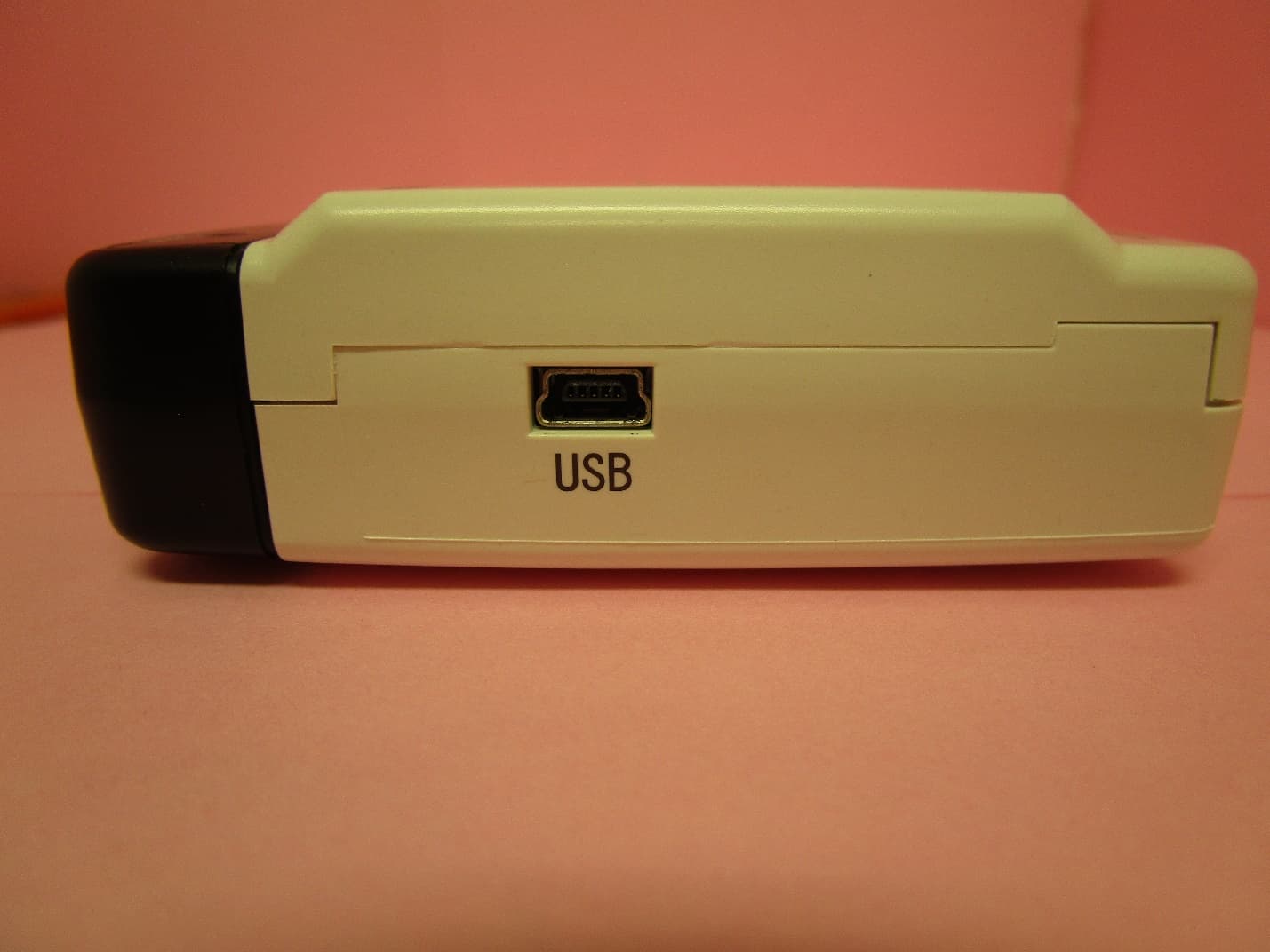
SRD10100
Dec 02, 2020Data Logger Base Unit
Equipment Class
DTS - Digital Transmission System