SRDRTR6XWIRELESS CORE TEMPERATURE DATA LOGGER
TandD Corporation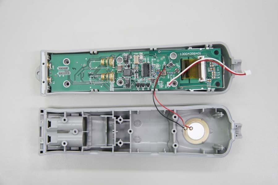
Click to zoom
Application Details
- Equipment Class
- DXX - Part 15 Low Power Communication Device Transmitter
- Date of Grant
- Nov 13, 2007
- Application Purpose
- Original Equipment
- Date of Application
- Nov 11, 2007
- Equipment Note
- WIRELESS CORE TEMPERATURE DATA LOGGER
- Frequency Range
- 902.28000000 - 927.64000000
- Company
- TandD Corporation
- Country
- Japan
Documents & Files
Document Text
Text extracted from the exhibit documents filed with the FCC. Open a document above to read the original.
Users Manual
What is RTR-61? ɜ Thermo Recorder Push Wireless RTR-61 is a handy-type device which acts both as a thermometer and a temperature recorder, which has been designed to easily measure and record the internal temperature of food items and liquid temperature using a needle-type sensor. ɜ This product has been designed to meet IP64 standards (splash resistant; rated for use in daily life). RTR-61 measures and records core temperature, which makes it suitable for use in the food production industry especially temperature management for HACCP. ɜ The unit incorporates a battery life warning function, which informs the user when it is time to replace the battery. When the battery power becomes low, all normal operations will stop in order to protect the data. ɜ The LCD Backlight allows the display to be easily read even in low light. The LCD contrast can also be easily adjusted for better viewing. ɜThese units are also designed with special short wave radio functions that when coupled with our exclusive software set "Push Wireless Communication Set (RTR-61SK)", makes it possible to carry out wireless communication, allowing for easy and effective management of multiple RTR-61 units. ɡBattery Life Indicator The battery indicator on the LCD display allows you to view the status of the battery life. If the remaining battery power becomes zero, a battery replacement message will appear. Once the message appears, please change the battery as soon as possible. Battery Life Indicator A battery replacement message will appear. If the batteries are further left, LCD display goes blank. ɡInstalling the Batteries ŏŐŕņ -If the LCD display goes blank and batteries are further left unchanged, recorded data may be erased. Please replace the batteries as soon as possible. -Make sure that the + and – are in the correct direction. If the battery terminals + / - are mistaken and a short occurs, all data stored in the main unit will be erased. -When opening the battery case to change the batteries, make sure no water or foreign object gets inside the case. -Make sure to change both batteries at the same time and use two batteries of the same type. Ӳ Lift up ӱ Push Ӳ Push it down until you hear a clicking sound ӱ Insert the top end of the cover into the unit 1.2.3. Open the RTR-61 by pushing up on the bottom of the battery case on the back of the unit. Insert 2 AAA alkaline batteries, making sure that the + and – are in the correct direction. (The + of two batteries should face toward the bottom of the case). Be sure to securely close the cover until you hear a clicking sound. ӱȁ Installing the Batteries Package of Contents Read the following for details about battery life and battery installation. Part Names and Functions ̋ Judgment LED (Red / Green) ȁȁ ̋ Ȥ The judgment result of temperature measurement will be shown. Out of Range: Red LED will fl ash. Within Range: Green LED will fl ash. ɖJudgment LED Settings By changing settings, it is possible to turn ON or OFF the Judgment LED function. ɡTemperature Sensor (Optional) All-in-One Short Type Ȭunitȇmmȭ RTR-6110 Short Type Sensor RTR-6130 Long Type Sensor Separate Short Type ȁȁȁȁȁȁȁȁȁ Ȭunitȇmmȭ RTR-6210 Short Type Sensor RTR-6230 Long Type Sensor ɡRTR-61 Series ӱRTR-61-110ȇAll-in-One Short Type Set ȁMain Unit + All-in-One Short Type Sensor ӲRTR-61-130ȇAll-in-One Long Type Set ȁ Main Unit + All-in-One Long Type Sensor ӳRTR-61-210ȇSeparate Short Type Set ȁ Main Unit + Separate Short Type Sensor ӴRTR-61-230ȇSeparate Long Type Set ȁMain Unit + All-in-One Long Type Sensor *Common Items Included: 2 AAA alkaline batteries User's Manual (this document) RTR-61 Main Unit (Sensor attached) AAA Alkaline Batteries (LR03) x 2 User's Manual Warranty (this document) LCD Display The RTR-61 is designed with a graphic LCD display with a resolution of 132 X 64 pixels. ɖBacklight Function The LCD Backlight makes the display easier to read in low light conditions. ɖContrast Adjustment Function The display contrast can be adjusted here. <MENU> button By pressing this button, the Menu will be displayed. Also, press to return to the previous window. <ENT> button Press to enter the settings menu or determine the settings. Optical Communication Area for communication with the Base Unit (RTR-50 / RTR-5W). If the unit gets dirty, wipe it with a clean cloth dipped in alcohol. Temperature Sensor As for details about how to remove or change the sensor, please see the User's Manual that comes with the sensor you will be using. Please be careful when handling the temperature sensor. PUSH Record LED (Orange) By pressing the <REC> button, the lamp will turn on when a temperature measurement is recorded. *The recorded object is the temperature at the instant when the <REC> button is pressed. <REC> button (Record) When this button is pressed, the Temperature, Date / Time, User Name, Item, and Judgment Result at the time of pressing are recorded into the RTR-61. Cursor buttons (Moving Up and Down) Press to move the Cursors up and down on the display. <ON / OFF> button (Power) Press to turn on / off the power. ɖAutomatic Power-OFF Function If the unit is not used for about fi ve minutes, it will automatically turn off. ɖAutomatic Power-ON Function If a unit is OFF, when wireless or optical communication is carried out by a Management Operator, that unit will be automatically turned ON. ɡProduct Specifi cations Measurement ItemTemperature Measurement Channels1 Channel Measurement RangeȽ25Ɏȡ235Ɏ Temperature Sensorthermistor Measurement Accuracy 10Ɏոئȁ ȁ: Ⱦ1.5Ɏ130Ɏȡ150Ɏ :Ⱦ1.0Ɏ 40Ɏȡ10Ɏ : Ⱦ1.0Ɏ150Ɏȡ180Ɏ :Ⱦ1.5Ɏ 40Ɏȡ85Ɏ : Ⱦ0.8Ɏ180Ɏȡ200Ɏ :Ⱦ2.0Ɏ 85Ɏȡ110Ɏ : Ⱦ0.5Ɏȁȁ200Ɏոષ :Ⱦ2.5Ɏ 110Ɏȡ130Ɏ :Ⱦ0.8Ɏ Measurement / Display Resolution 0.1Ɏ Measuring / Display Interval0.5sec Number of Recorded Data1800 data readings LCD Display Date and Time / Measured Value / Battery Life Warning Unit of Temperature (Ɏ/ȌF) / User / Items Temp. Judgment LED Display Out of Range: Red LED Blink Within Range: Green LED Blink Clock Resolution Mo…
Text truncated - open the document above for the full version.
Operational Description
ANTENNA SPECIFICATION Model: RTR-61 Frequency Range: 915MHz Gain: ≦2.14dB Type: Mono Pole Antenna 1/4 WaveLength Refer to 851-0439-7580.PDF
Test Report
TEST REPORT PER FCC PART 15.249 & IC RSS-210 UNLICENSED INTENTIONAL RADIATOR Applicant T AND D US, LLC Address PO BOX 321 Saratoga Springs, New York 12866 USA FCC ID SRDRTR6X IC Label IC: 5558A-RTR6X Model Number RTR-61 Product Description Wireless Core Temperatrue Data Logger Date Sample Received 10/17/2007 Date Tested 10/31/2007 Tested By Richard Block Approved By Mario de Aranzeta Report Number 3376AUT7TestReport.pdf Test Results PASS FAIL THE ATTACHED REPORT SHALL NOT BE REPRODUCED EXCEPT IN FULL WITHOUT THE WRITTEN APPROVAL OF TIMCO ENGINEERING, INC. 849 NW State Road 45 Newberry, FL 32669 USA Ph: 888.472.2424 or 352.472.5500 Fax: 352.472.2030 Email: [email protected] Website: www.timcoengr.com Certificate # 0955-01 APPLICANT: T AND D US, LLC FCC ID: SRDRTR6X, IC: 5558A-RTR6X Report #: W:\T\T&D_SRD\3376AUT7\3376AUT7TestReport Page 2 of 14 TABLE OF CONTENT ATTESTATION ................................................................................................................... 3 REPORT SUMMARY........................................................................................................... 4 TEST ENVIRONMENT AND TEST SETUP ........................................................................... 4 DUT SPECIFICATION......................................................................................................... 5 EMC EQUIPMENT LIST ..................................................................................................... 6 TEST PROCEDURES ......................................................................................................... 6 RADIATION INTERFERENCE ............................................................................................. 7 OCCUPIED BANDWIDTH ................................................................................................. 10 BAND EDGE COMPLIANCE ............................................................................................. 11 POWER LINE CONDUCTED INTERFERENCE................................................................... 13 APPLICANT: T AND D US, LLC FCC ID: SRDRTR6X, IC: 5558A-RTR6X Report #: W:\T\T&D_SRD\3376AUT7\3376AUT7TestReport Page 3 of 14 ATTESTATION The attached report shall not be reproduced except in full without the written permission of Timco Engineering Inc. Summary The device under test does: fulfill the general approval requirements as identified in this test report not fulfill the general approval requirements as identified in this test report Attestations This equipment has been tested in accordance with the standards identified in this test report. To the best of my knowledge and belief, these tests were performed using the measurement procedures described in this report. All instrumentation and accessories used to test products for compliance to the indicated standards are calibrated regularly in accordance with ISO 17025 requirements. Certificate # 0955-01 I attest that the necessary measurements were made, under my supervision, at: Timco Engineering Inc. 849 NW State Road 45 Newberry, Fl 32669 Authorized Signatory Name: Mario de Aranzeta Mario de Aranzeta C.E.T. Compliance Engineer/ Lab. Supervisor Date: November 7, 2007 APPLICANT: T AND D US, LLC FCC ID: SRDRTR6X, IC: 5558A-RTR6X Report #: W:\T\T&D_SRD\3376AUT7\3376AUT7TestReport Page 4 of 14 REPORT SUMMARY Disclaimer The test results relate only to the items tested. Purpose of Test To show the DUT in compliance with FCC CFR 47, Part 15.249 and Industry Canada RSS-210 Issue 7 requirements for 900 MHz low power radio. Test Standards FCC CFR 47 Part 15.249 IC RSS-210 ANSI C63.4: 2003 Related Approval(s)/Report(s) 3376CUT7TestReport.pdf TEST ENVIRONMENT AND TEST SETUP Test Facility RF output power and radiated emission were conducted by Timco Engineering Inc. located at 849 NW State Road 45, Newberry, FL 32669 USA Laboratory Test Condition Temperature: 26ºC Relative humidity: 50%. Deviation from the standards No deviation Modification to the DUT No modification. Test Exercise (e.g. software description, test signal, etc.) The DUT was placed in continuous transmitting mode of operation. System Setup Stand alone device. APPLICANT: T AND D US, LLC FCC ID: SRDRTR6X, IC: 5558A-RTR6X Report #: W:\T\T&D_SRD\3376AUT7\3376AUT7TestReport Page 5 of 14 DUT SPECIFICATION DUT Description WIRELESS CORE TEMPERATRUE DATA LOGGER FCC ID SRDRTR6X Model Number RTR-61 Operating Frequency TX: 902.3 – 927.1 MHz RX: Same No. of Channels 21 Modulations FM 110–120Vac/50– 60Hz DC Power DUT Power Source Battery Operated Exclusively Test Item Prototype Pre- Production Production Type of Equipment Fixed Mobile Portable Antenna Connector FCC Rules require that the antenna connector be unique. APPLICANT: T AND D US, LLC FCC ID: SRDRTR6X, IC: 5558A-RTR6X Report #: W:\T\T&D_SRD\3376AUT7\3376AUT7TestReport Page 6 of 14 EMC EQUIPMENT LIST Device Manufacturer Model Serial Number Cal/Char Date Due Date 3/10-Meter OATS TEI N/A N/A Listed 3/20/07 3/19/10 3-Meter OATS TEI N/A N/A Listed 1/11/06 1/10/09 Antenna: Biconnical Eaton 94455-1 1057 CAL 12/12/05 12/12/07 Antenna: Biconnical Eaton 94455-1 1096 CAL 10/11/06 10/11/08 Antenna: Biconnical Electro- Metrics BIA-25 1171 CAL 7/18/07 7/18/09 Analyzer Blue Tower Quasi-Peak Adapter HP 85650A 2811A01279 CAL 5/17/07 5/17/09 Analyzer Blue Tower RF Preselector HP 85685A 2926A00983 CAL 5/17/07 5/17/09 Analyzer Blue Tower Spectrum Analyzer HP 8568B 2928A04729 2848A18049 CAL 5/17/07 5/17/09 LISN Electro- Metrics ANS-25/2 2604 CAL 10/5/06 10/5/08 LISN Electro- Metrics EM-7820 2682 CAL 7/23/07 7/23/09 Antenna: Log-Periodic Eaton 96005 1243 CAL 12/14/05 12/14/07 APPLICANT: T AND D US, LLC FCC ID: SRDRTR6X, IC: 5558A-RTR6X REPORT: T\T&D_SRD\3376AT7\3376AT7TestReport Page 6 of 14 TEST PROCEDURES Radiation Interference: ANSI C63.4-2003 using a spectrum analyzer, a preselector, a quasi-peak adapter, and an appropriate antenna. The analyzer was calibrated in dB above a microvolt at the output of the antenna. The reso…
Text truncated - open the document above for the full version.
Contact Information
Applicant
Ryota Suzuki(Corporate Director)
Test Firm
Timco Engineering, Inc.Sid Sanders
Technical Specifications
| # | Rule Parts | Frequency Range | Power Output |
|---|---|---|---|
| 1 | 15C | 902.28 MHz - 927.64 MHz | - |
Other Applications from TandD Corporation
SRD50150
Sep 26, 2024Data Logger
Equipment Class
DTS - Digital Transmission System
SRD50140
Apr 08, 2023Data Logger
Equipment Class
DTS - Digital Transmission System
SRD50110
Jul 11, 2021Data Logger
Equipment Class
DTS - Digital Transmission System
SRD50100
Dec 02, 2020Data Logger Remote Unit
Equipment Class
DTS - Digital Transmission System
SRD10100
Dec 02, 2020Data Logger Base Unit
Equipment Class
DTS - Digital Transmission System