SW8WD6030USB Z-Wave dongle
Good Way Technology Co., Ltd.Application Details
- Equipment Class
- DXX - Part 15 Low Power Communication Device Transmitter
- Date of Grant
- Nov 16, 2013
- Application Purpose
- Original Equipment
- Date of Application
- Nov 13, 2013
- Equipment Note
- USB Z-Wave dongle
- Frequency Range
- 908.42000000 - 908.42000000
- Country
- Taiwan
Documents & Files
Document Text
Text extracted from the exhibit documents filed with the FCC. Open a document above to read the original.
Users Manual
WD6020/WD6030/WD6031/WD6032 (USB Z-Wave ® Dongle) User’s Manual 1. Software Specification ▓ Generic Device Class: GENERIC_TYPE_STATIC_CONYROLLER ▓ Specific Device Class: SPECIFIC_TYPE_PC_CONTROLLER ▓ Command Classes: COMMAND_CLASS_CONTROLLER_REPLICATION_V1 COMMAND_CLASS_BASIC_V1 COMMAND_CLASS_VERSION_V1 2. Hardware Specification 3. Installation 4. Product Specification ▓ Power:USB bus powered ▓ Interface:Compliant with USB 2.0 version specification. ▓ Full speed USB data transmission rate up to 12Mbps. ▓ Frequency:908.42(US)/868.42(EU)/ 922.5 MHz (JP) ▓ Data Rate: 100 kbps ▓ Operation Range:Up to 100 feet ▓ Operation Temperature:0~40 degree ▓ Regulatory Approvals:FCC/CE/TELEC Only for Android 5. You can scan the QR code .Download and installation the Z-control APP. 6. Regulatory Compliance FCC conditions FEDERAL COMMUNICATIONS COMMISSION INTERFERENCE STATEMENT This equipment has been tested and found to comply with the limits for a Class B digital device, pursuant to part 15 of the FCC Rules. These limits are designed to provide reasonable protection against harmful interference in a residential installation. This equipment generates, uses and can radiate radio frequency energy and, if not installed and used in accordance with the instructions, may cause harmful interference to radio communications. However, there is no guarantee that interference will not occur in a particular installation. If this equipment does cause harmful interference to radio or television reception, which can be determined by turning the equipment off and on, the user is encouraged to try to correct the interference by one or more of the following measures: ▓ Reorient or relocate the receiving antenna. ▓ Increase the separation between the equipment and receiver. ▓ Connect the equipment into an outlet on a circuit different from that to which the receiver is connected. ▓ Consult the dealer or an experienced radio/ TV technician for help. CAUTION: Any changes or modifications not expressly approved by the grantee of this device could void the user's authority to operate the equipment. This device complies with Part 15 of the FCC Rules. Operation is subject to the following two conditions: (1) this device may not cause harmful interference, and (2) this device must accept any interference received, including interference that may cause undesired operation. CE This equipment is in compliance with the requirements of the following regulations: EN 55 022: CLASS B WEEE Information For EU (European Union) member users: According to the WEEE (Waste electrical and electronic equipment) Directive, do not dispose of this product as household waste or commercial waste. Waste electrical and electronic equipment should be appropriately collected and recycled as required by practices established for your country. For information on recycling of this product, please contact your local authorities, your household waste disposal service or the shop where you purchased the product. 20131106
ID Label/Location Info
GOODWAY TECHNOLOGY CO., LTD. FCC ID.: SW8WD6030 3F, No. 135, Ln. 235, Baociao Rd., Sindian Dist., New Taipei City 231, Taiwan.Tel : +886 2 8919-1200 ext. 355 FCC ID Label
ID Label/Location Info
GOODWAY TECHNOLOGY CO., LTD. FCC ID.: SW8WD6030 3F, No. 135, Ln. 235, Baociao Rd., Sindian Dist., New Taipei City 231, Taiwan.Tel : +886 2 8919-1200 ext. 355 The FCC ID Label will be placed on the equipment as shown in the photograph below.
Test Report
Report No.: 139529R-RFUSP30V01 Page : 1 of 29 FCC Test Report Product Name USB Z-Wave dongle Model No. WD6020, WD6030 FCC ID. SW8WD6030 Applicant GOODWAY TECHNOLOGY CO., LTD. Address 3F, No. 135, Ln. 235, Baociao Rd., Sindian Dist., New Taipei City 231, Taiwan Date of Receipt Sep. 25, 2013 Issued Date Oct. 25, 2013 Report No. 139529R-RFUSP30V01 Report Version V1.0 The Test Results relate only to the samples tested. The test report shall not be reproduced except in full without the written approval of QuieTek Corporation. This report must not be used to claim product endorsement by TAF or any agency of the U.S. Government Report No.: 139529R-RFUSP30V01 Page : 2 of 29 Test Report Certification Issued Date: Oct. 25, 2013 Report No. : 139529R-RFUSP30V01 Product Name USB Z-Wave dongle Applicant GOODWAY TECHNOLOGY CO., LTD. Address 3F, No. 135, Ln. 235, Baociao Rd., Sindian Dist., New Taipei City 231, Taiwan Manufacturer GOODWAY TECHNOLOGY CO., LTD. Model No. WD6020, WD6030 FCC ID. SW8WD6030 EUT Rated Voltage DC 5V (by USB port) EUT Test Voltage AC 120V/60Hz Trade Name GOODWAY Applicable Standard FCC CFR Title 47 Part 15 Subpart C: 2012 ANSI C63.4: 2003, ANSI C63.10: 2009 Test Result Complied The Test Results relate only to the samples tested. The test report shall not be reproduced except in full without the written approval of QuieTek Corporation. This report must not be used to claim product endorsement by TAF or any agency of the U.S. Government Documented By : ( Senior Adm. Specialist / Rita Huang ) Tested By : ( Engineer / Vincent Chu ) Approved By : ( Manager / Vincent Lin ) Report No.: 139529R-RFUSP30V01 Page : 3 of 29 TABLE OF CONTENTS Description Page 1. GENERAL INFORMATION................................................................................................................4 1.1. EUT Description ......................................................................................................................................4 1.2. Operation Description ..............................................................................................................................5 1.3. Tested System Details ..............................................................................................................................5 1.4. Configuration of Test System...................................................................................................................6 1.5. EUT Exercise Software............................................................................................................................6 1.6. Test Facility..............................................................................................................................................7 2. Conducted Emission ..............................................................................................................................8 2.1. Test Equipment ........................................................................................................................................8 2.2. Test Setup .................................................................................................................................................8 2.3. Limits .......................................................................................................................................................9 2.4. Test Procedure..........................................................................................................................................9 2.5. Uncertainty...............................................................................................................................................9 2.6. Test Result of Conducted Emission .......................................................................................................10 3. Radiated Emission ...............................................................................................................................12 3.1. Test Equipment ......................................................................................................................................12 3.2. Test Setup ...............................................................................................................................................13 3.3. Limits .....................................................................................................................................................14 3.4. Test Procedure........................................................................................................................................15 3.5. Uncertainty.............................................................................................................................................15 3.6. Test Result of Radiated Emission ..........................................................................................................16 4. Band Edge.............................................................................................................................................22 4.1. Test Equipment ......................................................................................................................................22 4.2. Test Setup ...............................................................................................................................................23 4.3. Limit.......................................................................................................................................................23 4.4. Test Procedure........................................................................................................................................24 4.5. Uncertainty.............................................................................................................................................24 4.6. Test Result of Band Edge...............................................................…
Text truncated - open the document above for the full version.
Test Setup Photos
Report No.: 139529R-RFUSP30V01 Page : 1 of 3 Attachment 1: EUT Test Setup Photographs Front View of Conducted Test Back View of Conducted Test Report No.: 139529R-RFUSP30V01 Page : 2 of 3 Front View of Radiated Test Back View of Radiated Test Report No.: 139529R-RFUSP30V01 Page : 3 of 3 Front View of Radiated Test (Horn) Back View of Radiated Test (Horn)
Contact Information
Applicant
Alex Lee(Manager)
Technical Contact
QuieTek CorporationMaggie Chen
[email protected]886-2-86013788
No.5-22,Rueishu Keng, Linkou Dist · New Taipei City · Taiwan
Test Firm
DEKRA Testing and Certification Co., Ltd.Sky Hsu
Technical Specifications
| # | Rule Parts | Frequency Range | Power Output |
|---|---|---|---|
| 1 | 15C | 908.42 MHz - 908.42 MHz | - |
Other Applications from Good Way Technology Co., Ltd.
SW8SD42000N1
Mar 17, 2024Human Presence Sensor
Equipment Class
DTS - Digital Transmission System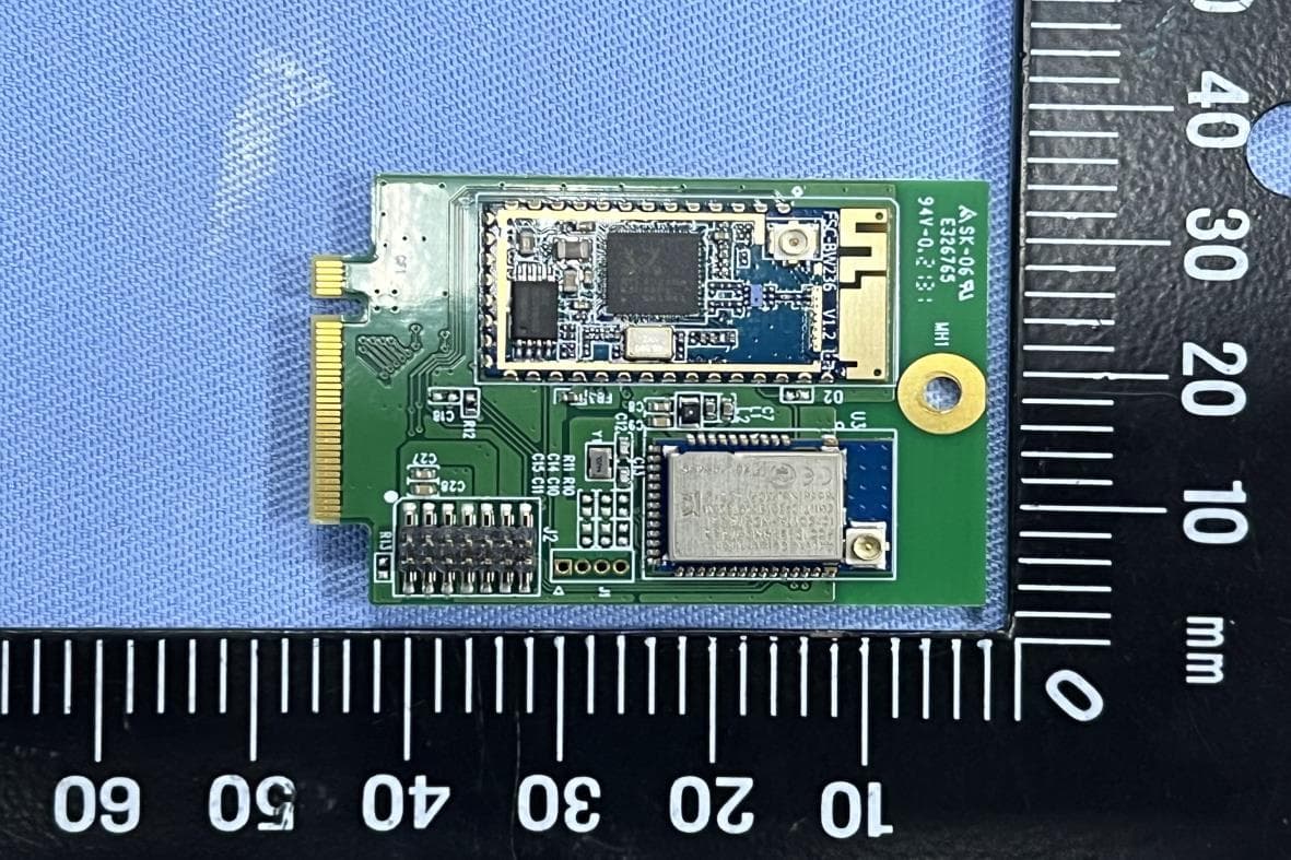
SW8TM51010
Jun 05, 2022Wi-Fi & BLE M.2 Wireless Module
Equipment Class
NII - Unlicensed National Information Infrastructure TX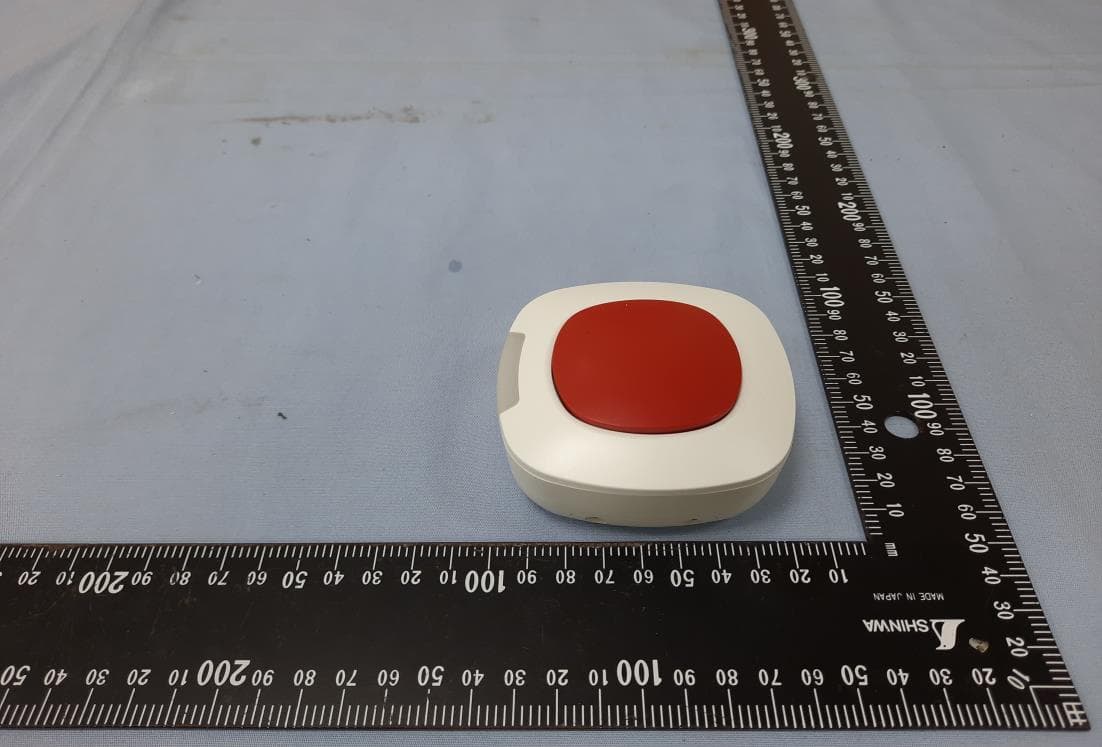
SW8TR1B100Z1S
Jul 12, 2020Scene Button
Equipment Class
DXX - Part 15 Low Power Communication Device Transmitter
SW8ZGATE
Oct 08, 2014802.11b/g/n and Z-WAVE
Equipment Class
DXX - Part 15 Low Power Communication Device Transmitter
SW8-WD9012R1
Sep 18, 2014HP Wireless Streaming Connector
Equipment Class
DTS - Digital Transmission System