SW8WD9007USB TV Dongle
Good Way Technology Co., Ltd.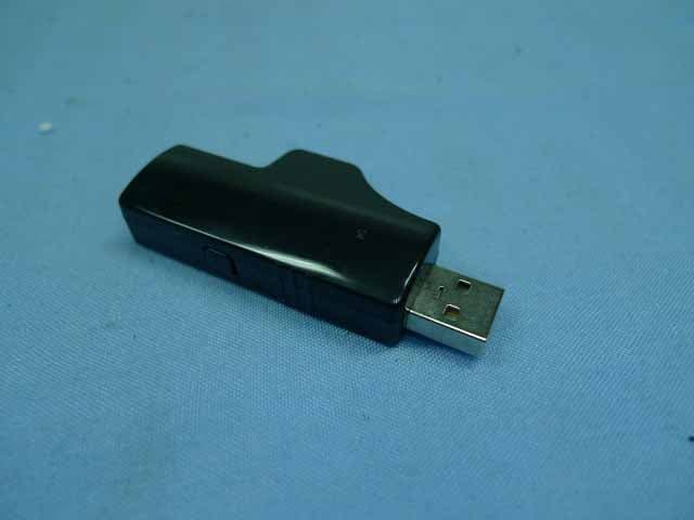
Click to zoom
Application Details
- Equipment Class
- DSS - Part 15 Spread Spectrum Transmitter
- Date of Grant
- Jun 25, 2010
- Application Purpose
- Original Equipment
- Date of Application
- Jun 23, 2010
- Equipment Note
- USB TV Dongle
- Frequency Range
- 2406.00000000 - 2472.00000000
- Country
- Taiwan
Documents & Files
Document Text
Text extracted from the exhibit documents filed with the FCC. Open a document above to read the original.
Users Manual
USB TV Dongle User’s Manual USB TV Dongle User’s Manual i ABOUT THIS MANUAL This manual is designed for use with the USB TV Dongle. Information in this document has been carefully checked for accuracy; however, no guarantee is given to the correctness of the contents. The information in this document is subject to change without notice. The manufacturer does not make any representations or warranties (implied or otherwise) regarding the accuracy and completeness of this document and shall in no event be liable for any loss of profit or any commercial damage, including but not limited to special, incidental, consequential, or other damage. SAFETY INSTRUCTIONS Always read the safety instructions carefully: Keep this User’s Manual for future reference Keep this equipment away from humidity If any of the following situation arises, get the equipment checked by a service technician: • The equipment has been exposed to moisture. • The equipment has been dropped and damaged. • The equipment has obvious sign of breakage. • The equipment has not been working well or you cannot get it to work according to the User’s Manual. COPYRIGHT This document contains proprietary information protected by copyright. All right are reserved. No part of this manual may be reproduced by any mechanical, electronic or other means, in any form, without prior written permission of the manufacturer. USB TV Dongle User’s Manual 1 Introduction This USB TV Dongle enables you wirelessly transmit sound form your TV to the Wireless Headphone. Without messy wires, just simply connecting the USB TV Dongle to your TV ‘s or media player ‘s USB and audio port, it can enable wireless audio connection between your device and headphone. USB TV Dongle User’s Manual 2 Features No more wires, and less cable clutter Proprietary 2.4GHz Wireless solution Special design for Media player and LED/LCD TV sets that come with USB ports. Low power consumption / Low audio noise Support 1-n Broadcasting Innovative transmission dongle can connect to all kinds of Media Players and TV sets that comes with the USB port. By using the USB power on Media Player and TV set, it doesn’t need extra power adapter for TV dongle side. Package Contents USB TV Dongle x1 Wireless Headphone x1 User’s Manual x1 Connection Cable x1 AAA Battery X2 How to use: 1. Plugging the USB TV Dongle into the player device (TV, DVD, NAS, etc.,) USB port, now, the power indicator (Blue) will light up continuingly. USB TV Dongle User’s Manual 3 2. Connecting the USB TV Dongle with connection cable to the player device (TV, DVD, NAS, etc.,), 3.5mm plug to the transmitter audio hole; RCA plug to TV(DVD, NAS, etc.) RCA Output. 3. Pressing lightly on the headphone power switch for 3 seconds to turn on the headphone power, now, the power indicator (Green) will light up continuingly. 4. Wearing on properly the headphones and enjoying cozily and happily the wireless freedom and relaxation. 5. Adjusting the volume button to choose the right volume level. If you want to do an association between the USB TV Dongle and the headphone, please follow the operation procedure below: Press the transmitter pairing bottom over 3 seconds first and then press the the headphone pair bottom over 3 seconds until you heard the “bi” sound in the headphone to indictor the association successfully. USB TV Dongle User’s Manual 4 Regulatory Compliance FCC Conditions This equipment has been tested and found to comply with Part 15 of the FCC Rules. Operation is subject to the following two conditions: (1) This device may not cause harmful interference (2) This device must accept any interference received. Including interference that may cause undesired operation. Important! Changes or modifications not expressly approved by the manufacturer responsible for compliance could void the user’s authority to operate the equipment. Use an approved phone set. Note: This equipment has been tested and found to comply with the limits for a Class B digital device, pursuant to part 15 of the FCC Rules. These limits are designed to provide reasonable protection against harmful interference in a residential installation. This equipment generates, uses and can radiate radio frequency energy and, if not installed and used in accordance with the instructions, may cause harmful interference to radio communications. However, there is no guarantee that interference will not occur in a particular installation. If this equipment does cause harmful interference to radio or television reception, which can be determined by turning the equipment off and on, the user is encouraged to try to correct the interference by one or more of the following measures: —Reorient or relocate the receiving antenna. —Increase the separation between the equipment and receiver. —Connect the equipment into an outlet on a circuit different from that to which the receiver is connected. —Consult the dealer or an experienced radio/TV technician for help. USB TV Dongle User’s Manual 5 CE This equipment is in compliance with the requirements of the following regulations: EN 55 022: CLASS B WEEE Information For EU (European Union) member users: According to the WEEE (Waste electrical and electronic equipment) Directive, do not dispose of this product as household waste or commercial waste. Waste electrical and electronic equipment should be appropriately collected and recycled as required by practices established for your country. For information on recycling of this product, please contact your local authorities, your household waste disposal service or the shop where you purchased the product. FCC ID: SW8WD9007
External Photos
Page 1 Figure 1 General Appearance (Front View) Figure 2 General Appearance (Back View) Good Way USB TV Dongle FCC ID: SW8WD9007
Internal Photos
Page 1 Figure 1 PCB (Front View) Figure 2 PCB (Back View) Good Way USB TV Dongle FCC ID: SW8WD9007 Page 2 Figure 3 Crystal Oscillator
RF Exposure Info
RF Exposure Statement 1. Standard Applicable According to 1.1307 (b)(1), systems operating under the provisions of this section shall be operated in a manner that ensure that the public is not exposed to radio frequency energy level in excess of the Commission’s guideline. This is a portable device. 2. Measurement Result: This is a portable device and the max peak output power is 4.39 dBm (2.75mW). Lower than the low threshold 60/f GHz = (24.27 mW), d<2.5 cm general population category. The SAR/MPE measurement is not necessary.
Test Report
FCC ID: SW8WD9007 Page 1 of 51 Audix Technology (Wujiang) Co., Ltd. EMC Dept. Report No.: ACWE-F1003001 APPLICATION FOR CERTIFICATION On Behalf of GOOD WAY TECHNOLOGY CO., LTD. USB TV Dongle Model No. : WD9007Y1 Brand : Good Way FCC ID : SW8WD9007 Prepared for GOOD WAY TECHNOLOGY CO., LTD. 3F, No. 135, Lane 235, Pau Chiao Rd., Hsin-Tien City, Taipei Hsien, Taiwan, R.O.C. Prepared by Audix Technology (Wujiang) Co., Ltd. EMC Dept. No. 1289 Jiangxing East Road, the Part of Wujiang Economic Development Zone Jiangsu China 215200 Tel : +86-512-63403993 Fax :+86-512-63403339 Report Number ACWE-F1003001 Date of Test Feb.25~Mar.02, 2010 Date of Report Mar. 03, 2010 FCC ID: SW8WD9007 Page 2 of 51 Audix Technology (Wujiang) Co., Ltd. EMC Dept. Report No.: ACWE-F1003001 TABLE OF CONTENTS Description Page TEST REPORT CERTIFICATION .......................................................................................................4 1. SUMMARY OF MEASUREMENTS AND RESULTS .............................................................5 2. GENERAL INFORMATION.......................................................................................................6 2.1. Description of Device (EUT).................................................................................................................. 6 2.2. Operating Condition of EUT .................................................................................................................. 6 2.3. Description of Test Facility .................................................................................................................... 7 2.4. Measurement Uncertainty....................................................................................................................... 7 3. CONDUCTED EMISSION MEASUREMET ............................................................................8 3.1. Test Equipment ....................................................................................................................................... 8 3.2. Block Diagram of Test Setup.................................................................................................................. 8 3.3. Power line Conducted Emission Limit (FCC Part15 section 15.207) .................................................... 8 3.4. Test Procedure ........................................................................................................................................ 9 3.5. Conducted Emission Measurement Results............................................................................................ 9 4. RADIATED EMISSION MEASUREMENT ............................................................................12 4.1. Test Equipment ..................................................................................................................................... 12 4.2. Block Diagram of Test Setup (At 3M Semi-Anechoic chamber) ......................................................... 12 4.3. Radiated Emission Limits (FCC Part15 section 15.209) ...................................................................... 13 4.4. Test Procedure ...................................................................................................................................... 14 4.5. Test Results........................................................................................................................................... 15 5. 20 DB BANDWIDTH MEASUREMENT .................................................................................34 5.1. Test Equipment ..................................................................................................................................... 34 5.2. Block Diagram of Test Setup................................................................................................................ 34 5.3. Specification Limits (§15.247(a)(1)) .................................................................................................... 34 5.4. Test Procedure ...................................................................................................................................... 34 5.5. Test Results........................................................................................................................................... 34 6. CARRIER FREQUENCY SEPARATION MEASUREMENT ..............................................37 6.1. Test Equipment ..................................................................................................................................... 37 6.2. Block Diagram of Test Setup................................................................................................................ 37 6.3. Specification Limits (§15.247(a)(1)(iii)) .............................................................................................. 37 6.4. Test Procedure ...................................................................................................................................... 37 6.5. Test Results........................................................................................................................................... 37 7. TIME OF OCCUPANCY MEASUREMENT ..........................................................................40 7.1. Test Equipment ..................................................................................................................................... 40 7.2. Block Diagram of Test Setup................................................................................................................ 40 7.3. Specification Limits (§15.247(a)(1)(iii)) .............................................................................................. 40 7.4. Test Procedure ...................................................................................................................................... 40 7.5. Test Results.........................................................................…
Text truncated - open the document above for the full version.
Test Setup Photos
FCC ID. SW8WD9007 Page 1 of 4 Audix Technology (Wujiang) Co., Ltd. EMC Dept. Report No.: ACWE-F1003001 1. PHOTOGRAPHS 1.1. Conducted Emission measurement Front View of Conducted Measurement Side View of Conducted Measurement FCC ID. SW8WD9007 Page 2 of 4 Audix Technology (Wujiang) Co., Ltd. EMC Dept. Report No.: ACWE-F1003001 1.2. Radiated Emission measurement 1.2.1. Frequency Range 30MHz~1GHz at Semi-Anechoic Chamber Front View of Radiated Emission Test (Working) Back View of Radiated Emission Test (Working) FCC ID. SW8WD9007 Page 3 of 4 Audix Technology (Wujiang) Co., Ltd. EMC Dept. Report No.: ACWE-F1003001 Front View of Radiated Emission Test (Transmitting) Back View of Radiated Emission Test (Transmitting) FCC ID. SW8WD9007 Page 4 of 4 Audix Technology (Wujiang) Co., Ltd. EMC Dept. Report No.: ACWE-F1003001 1.2.2. Frequency Range Above 1GHz at Semi-Anechoic Chamber 1.3. Photo of Section 5 ~ 11
Contact Information
Applicant
Alex Lee(Manager)
Technical Contact
Audix Technology (WuJiang)Co.,Ltd.Kin Lin
[email protected]0512-63403993
No.1289, Jiang Xing East Road,The Eastern Part of · Wujiang · China
Non-Technical Contact
Audix Technology (WuJiang)Co.,Ltd.Allen Wang
[email protected]0512-63403993
Test Firm
Audix Technology(WuJiang)Co.,LtdAllen Wang
Technical Specifications
| # | Rule Parts | Frequency Range | Power Output |
|---|---|---|---|
| 1 | 15C | 2.41 GHz - 2.47 GHz | 3.00 mW |
Other Applications from Good Way Technology Co., Ltd.
SW8SD42000N1
Mar 17, 2024Human Presence Sensor
Equipment Class
DTS - Digital Transmission System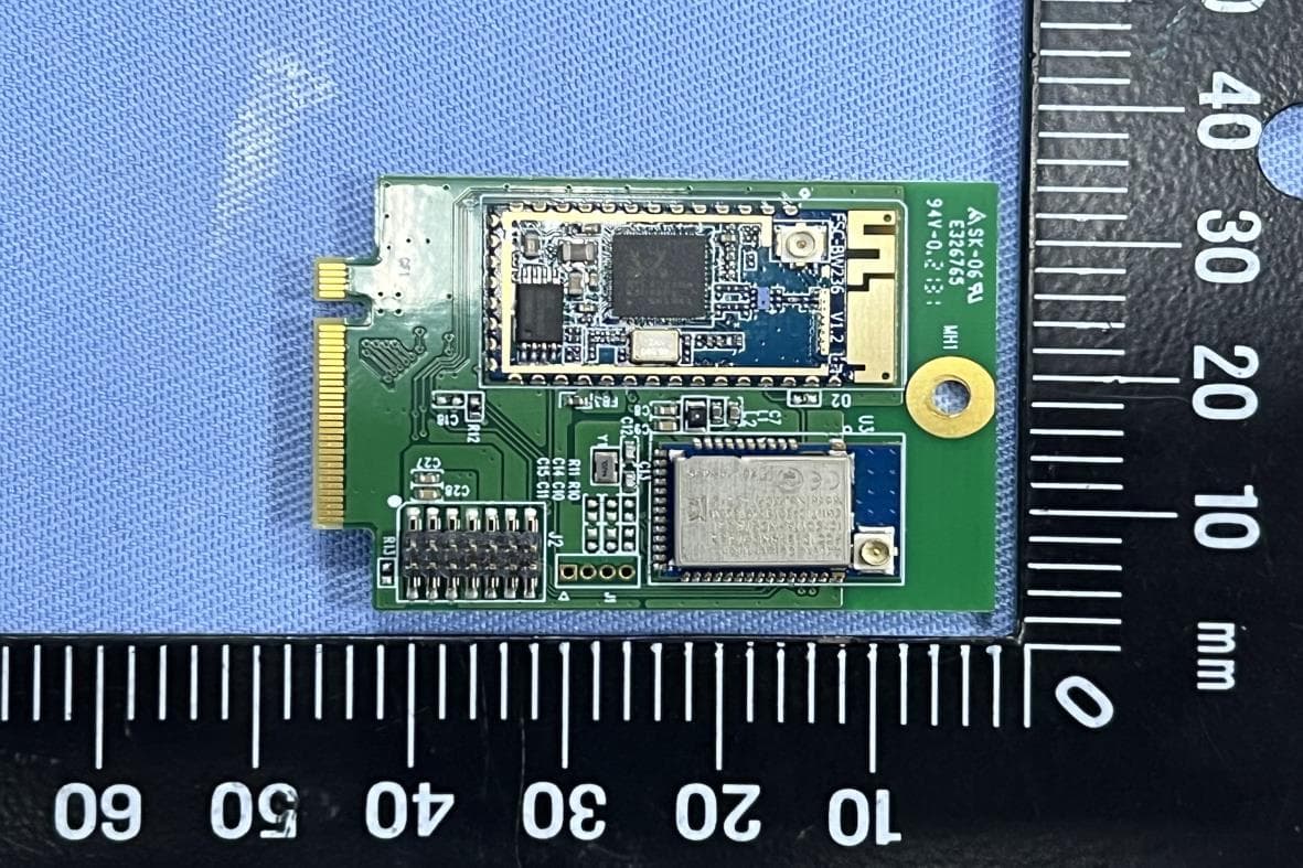
SW8TM51010
Jun 05, 2022Wi-Fi & BLE M.2 Wireless Module
Equipment Class
NII - Unlicensed National Information Infrastructure TX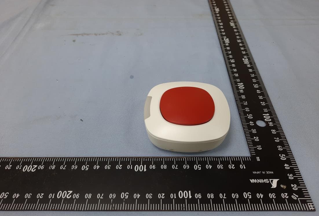
SW8TR1B100Z1S
Jul 12, 2020Scene Button
Equipment Class
DXX - Part 15 Low Power Communication Device Transmitter
SW8ZGATE
Oct 08, 2014802.11b/g/n and Z-WAVE
Equipment Class
DXX - Part 15 Low Power Communication Device Transmitter
SW8-WD9012R1
Sep 18, 2014HP Wireless Streaming Connector
Equipment Class
DTS - Digital Transmission System