T5E-200396Locator
3M Company - Scott Technologies, Inc.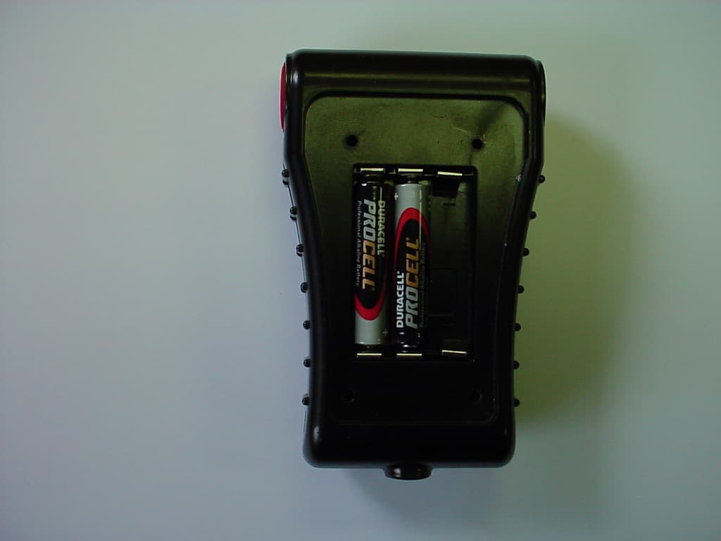
Click to zoom
Application Details
- Equipment Class
- DTS - Digital Transmission System
- Date of Grant
- Aug 07, 2006
- Application Purpose
- Original Equipment
- Date of Application
- Aug 07, 2006
- Equipment Note
- Locator
- Frequency Range
- 2425.00000000 - 2425.00000000
- Country
- United States
Documents & Files
Document Text
Text extracted from the exhibit documents filed with the FCC. Open a document above to read the original.
Users Manual
DRAFT COPY OPERATIONAL INSPECTION Complete operational inspection of the Personal Trans- mitter requires use of the Hand Held Receiver 1.To test the manual alarm, press either of the two manual alarm buttons on the Personal Transmitter. a) The Personal Transmitter shall sound a loud almost continuous 2 tone chirp accompanied by flashing of the red signal light. NOTE IF A LOW BATTERY INDICATION OCCURS AT ANY TIME DURING REGULAR OPERATIONAL INSPECTION, DO NOT USE THE EQUIPMENT. CHANGE THE BATTERIES AS REQUIRED AND REPEAT THE REGULAR OPERATIONAL TEST OR TAKE THE EQUIPMENT OUT OF SERVICE UNTIL THE BATTERIES ARE CHANGED AND THE REGULAR OPERATIONAL TEST IS SUCCESSFULLY PERFORMED. VISUAL INSPECTION 1.Visually inspect the Personal Transmitter enclosure for cracks or other damage. If any damage is found, remove the unit from service and tag for replacement. 2.Verify that the label with the Personal Transmitter ID Number is clear and legible. 3.Turn on the Personal Transmitter by removing the lanyard. Verify that the unit sounds and lights properly. The Personal Transmitter shall sound a loud almost continuous 3 tone chirp accompanied by flashing of the red signal light. 4.Battery Life – The Personal Transmitter will chirp once every three seconds to indicate the batteries are low and require changing. If the low battery indication occurs during the REGULAR OPERATIONAL INSPECTION, replace the batteries before proceeding with the inspection. See the BATTERY INSTALLATION section of this instruction. REGULAR OPERATIONAL INSPECTION WARNING FOLLOW REGULAR OPERATIONAL INSPECTION PRO- CEDURE EXACTLY. IF THE SCOTT PAK-TRACKER LOCATOR SYSTEM DOES NOT ACTUATE, OR DOES NOT OPERATE AS DESCRIBED OR IF ANY OTHER OPERA- TIONAL MALFUNCTION IS NOTED, DO NOT USE THE EQUIPMENT. FAILURE TO PROPERLY IDENTIFY MAL- FUNCTIONS MAY RESULT IN SERIOUS INJURY OR DEATH. WARNING FAILURE TO REGULARLY INSPECT THE SCOTT PAK- TRACKER LOCATOR SYSTEM EQUIPMENT, AS DESCRIBED IN THIS INSTRUCTION OR FAILURE TO IDEN- TIFY DAMAGE TO THE EQUIPMENT, MAY IMPAIR THE INTRINSIC SAFETY OF THE EQUIPMENT. THE INSTAL- LATION OF INCORRECT BATTERIES OR SUBSTITUTION OF ANY OTHER COMPONENTS MAY IMPAIR THE INTRIN- SIC SAFETY OF THE EQUIPMENT. IF THE EQUIPMENT IS USED IN AN EXPLOSIVE OR FLAMMABLE ATMOSPHERE, IMPAIRING THE INTRINSIC SAFETY OF THE EQUIPMENT MAY LEAD TO A FIRE OR AN EXPLOSION WHICH COULD RESULT IN SERIOUS INJURY OR DEATH. b) The Hand Held Receiver will sound an alert and display the Identification Number of the Personal Transmitter which appears on the label on the transmitter battery cover. c)Press the ENTER button ONCE on the Hand Held Receiver to select the displayed ID number d) Point the Hand Held Receiver directly at and in close proximity to the Personal Transmitter. The signal strength displayed will be at its highest value. 2.Reset the manual alarm by pressing simultaneously on both buttons located on the sides of the Personal Transmitter a) The unit will sound three chirps and the green light will flash. b) The Hand Held Receiver will reset to its non- alarm state. 3.Repeat the test in step 1 using the other manual alarm button. 4.To check the motion detector, leave the Personal Transmitter motionless for thirty (30) seconds. a) The Personal Transmitter shall sound a loud almost continuous 2 tone chirp accompanied by flashing of the red signal light after ten (10) seconds. b) The Hand Held Receiver will sound an alarm and display the Identification Number of the Personal Transmitter which appears on the label on the transmitter battery cover. c)Press the ENTER button ONCE on the Hand Held Receiver to select the displayed ID number d) Point the Hand Held Receiver directly at and in close proximity to the Personal Transmitter. The signal strength displayed will be at its highest value. 4.Turn the Personal Transmitter OFF by re-inserting the lanyard. The unit will sound a two tone chirp and the green light will go out. Install or replace batteries in the Personal Transmitter as follows: 1.Using a #1 Phillips screwdriver, loosen the four screws holding the battery cover. The screws are captive in the cover. See FIGURE 1. 2. Remove the old batteries and dispose of in accordance with state or local regulations. 3.Install three fresh batteries of the type designated. Orient the plus “+” and minus “-” ends of the batteries as illustrated inside the battery compartment. 4.Inspect the gasket on the inside of the battery cover for cuts or damage that might cause a leak. If any damage is found, remove the unit from service and tag for repair by authorized personnel. 5.Replace the battery cover and thread the four screws in alternately Place the Battery Cover with gasket onto the Personal Transmitter housing and secure the four (4) screws using the #1 Phillips screw driver. Evenly tighten the four cover screws by moving across the cover in an “X” pattern, turning each screw 1 to 2 times until cover is fully seated. 6.Test the operation of the Personal Transmitter according to the REGULAR OPERATIONAL INSPECTION section of this instruction. BATTERY INSTALLATION FOR THE PERSONAL TRANSMITTER The Personal Transmitter requires three (3) AAA batteries for operation. Use only three fresh batteries of the type specified. Batteries must only be installed or changed in an area known to be nonflammable. WARNING DISPOSE OF DAMAGED OR DEPLETED BATTERIES IN ACCORDANCE WITH FEDERAL, STATE, AND LOCAL EN- VIRONMENTAL REGULATIONS. DO NOT THROW AWAY DAMAGED BATTERIES AS ORDINARY TRASH. FAILURE TO HANDLE BATTERY PROPERLY MAY RESULT IN SERI- OUS INJURY. 1 Duracell is a registered trademark of The Gillette Company, Boston, MA. 2 Energizer and Eveready are registered trademarks of Eveready Battery Company, Inc., St. Louis, MO. NOTE DO NOT MIX BATTERY TYPES IN THE PERSONAL TRANSMITTER. ONLY USE THREE OF THE SAME KIND OF BATTERY IN THE UNIT AT ONE TIME. MIXING BATTERY TYPES MAY AFFECT THE PERFORMANCE OF THE PERSONAL TRANSMITTER. DO NOT USE RECHARGEABLE BATTERIES IN THE…
Text truncated - open the document above for the full version.
Cover Letter(s)
Scott Health & Safety 4320 Goldmine Road Monroe, NC 28110 U.S.A. Fire & Security Scott Health & Safety Tele:704.291.8395 Fax: 704.291.8380 e-mail: [email protected] Date: 04/04/2006 Time: 10:30 To: FCC Authorization & Evaluation Division 7435 Oakland Mills Road Columbia, MD 21045-0429 From: Klaus Wilkens Phone: 704-291-8395 Certification and Regulation Engineer Fax: 704-291-8380 Applicant: Scott Health & Safety Division of Scott Technologies, Inc. EMail: [email protected] ______________________________________________________________________________________ Subject: Request for Non disclosure for FCC ID: T5E -200396 To Whom It May Concern: Pursuant to 47 CFR Section 0.459, Scott Health & Safety Division of Scott Technologies, Inc. hereby requests non disclosure and confidential treatment of the following materials submitted in support of FCC certification application for FCC ID # T5E - 200396 a. Schematic Diagrams b. Operational Description c. Block Diagram Above materials contain trade secrets, proprietary and technical information which would customarily be guarded from competitors under 47 CFR section 0.457(d)(2). Disclosure or publication of any portion of this company confidential material to other parties could cause substantial competitive harm and provide unjustified benefits for competitors. Scott Health & Safety Division of Scott Technologies, Inc. understands that pursuant to 47 CFR section 0.457(d)(1)(ii) disclosure of the applicant and all accompanying documentation will not be made before the date of the grant. Sincerely yours, By: Klaus Wilkens Title: Certification and Regulation Engineer, Scott Health & Safety Division of Scott Technologies, Inc ____________________________________________________________________________________
Cover Letter(s)
Scott Health & Safety 4320 Goldmine Road Monroe, NC 28110 U.S.A. Fire & Security Scott Health & Safety Tele:704.291.8395 Fax: 704.291.8380 e-mail: [email protected] Date: 4 April 2006 Time: 10 : 05 To: FCC Authorization & Evaluation Division 7435 Oakland Mills Road Columbia, MD 21045-0429 From: Klaus Wilkens Phone: 704-291-8395 Certification and Regulation Engineer Fax: 704-291-8380 Applicant: Scott Health & Safety Division of Scott Technologies, Inc. EMail: [email protected] ______________________________________________________________________________________ Dear Ladies and/or Gentlemen: I appoint Kenneth L. Boston, James Blaha and Teresa White at L.S. Compliance, Inc., to act as an agent in the preparation of applications under Part 15 of the rules and regulations of the Federal Communications Commission. I certify that the exhibitions properly describe the device being submitted under this application and will implement any changes described in the test report. The labels described will be affixed to each item. The following statement is required by the Federal Communications Commission: By checking Yes, the applicant certifies that, in the case of an individual applicant, he or she is not subject to a denial of federal benefits, that included FCC benefits, pursuant to section 5301 of the Anti-Drug Abuse Act of 1988, 21 U.S.C 853(a), or, in the case of a non-individual applicant (e.g. corporation, partnership, or other unincorporated association), no party to the application is subject to a denial of federal benefits, that includes FCC benefits, pursuant to that section. ___X___Yes _______No By: Klaus Wilkens Title: Certification and Regulation Engineer, Scott Health & Safety Division of Scott Technologies, Inc.
External Photos
Scott Health & Safety Division of Scott Technologies, Inc. Pak Tracker Locator System FCC ID#: T5E-200396 Photo One – External Front View Scott Health & Safety Division of Scott Technologies, Inc. Pak Tracker Locator System FCC ID#: T5E-200396 Photo Two – External Back Side with FCC ID Label Scott Health & Safety Division of Scott Technologies, Inc. Pak Tracker Locator System FCC ID#: T5E-200396 Photo Three – External Close-Up of FCC ID Label Scott Health & Safety Division of Scott Technologies, Inc. Pak Tracker Locator System FCC ID#: T5E-200396 Photo Four – External Battery Compartment. Cover held in place with screws
ID Label/Location Info
LABEL MATERIAL: .0025 THK. DISTRUCTIBLE WHITE VINYL LABEL. Clarification: Label is destructible in the sense that if someone tries to remove it to use on another device, it tears. However, it is flame and heat resistant and indelible.
Internal Photos
Scott Health & Safety Division of Scott Technologies, Inc. Pak Tracker Locator System FCC ID#: T5E-200396 Photo One – Internal Open for Inspection Scott Health & Safety Division of Scott Technologies, Inc. Pak Tracker Locator System FCC ID#: T5E-200396 Photo Two – Internal Radio/RF Section Shielded PCB Antenna to the Right Scott Health & Safety Division of Scott Technologies, Inc. Pak Tracker Locator System FCC ID#: T5E-200396 Photo Three – Internal Shield Removed. RF Section Close-Up Scott Health & Safety Division of Scott Technologies, Inc. Pak Tracker Locator System FCC ID#: T5E-200396 Photo Four – Internal PCB Antenna Scott Health & Safety Division of Scott Technologies, Inc. Pak Tracker Locator System FCC ID#: T5E-200396 Photo Five – Internal PCB Flip-Side of RF Section/PCB Antenna Scott Health & Safety Division of Scott Technologies, Inc. Pak Tracker Locator System FCC ID#: T5E-200396 Photo Six – Internal PCB Side
RF Exposure Info
July 17, 2006 RF Exposure Threshold Computation – Tyco Personal Transmitter According to the calculations above, this portable device complies with FCC’s RF exposure limits for general population. Transmit packet on time: 0.87 (mS) Packet repetition time: 173.00 (mS) Maximum peak output power at antenna input terminal: 19.2 (dBm) Antenna gain(typical): 6.2 (dBi) Antenna gain(typical): 4.17 (numeric) Maximum peak output power at antenna output: 25.40 (dBm) Maximum peak output power at antenna output: 346.74 (mW) Source-based time-averaged power, conducted: 1.75 (mW) Maximum peak radiated output: 117.00 (dBuV/m @ 3m) Maximum peak radiated output: 21.80 (dBm) Maximum peak radiated output: 151.36 (mW) Source-based time-averaged power, radiated: 0.76 (mW) Low threshold for d<2.5 cm at 2.425 GHz: 24.74 (mW) Low threshold for d>2.5 cm at 2.425 GHz: 49.48 (mW) In both cases, computed and measured, the output power is below the low threshold for all separation distances greater than and less than 2.5 cm. LS Research, LLC TCB Response: Scott FCC ID #: T5E-200396 Page 2 of 5 Figure 1. Transmitter packet "on" time is 872 μS. Figure 2. Transmitter packet repetition time is 173 mS. LS Research, LLC TCB Response: Scott FCC ID #: T5E-200396 Page 3 of 5 Figure 3. Minimum antenna separation from the user is 2.9 cm. Figure 4. Product being worn in position 1. LS Research, LLC TCB Response: Scott FCC ID #: T5E-200396 Page 4 of 5 Figure 5. Product being worn in position 1. Figure 6. Product being worn in position 2. LS Research, LLC TCB Response: Scott FCC ID #: T5E-200396 Page 5 of 5 Figure 7. Product being worn in position 3
Test Report
LS Research, LLC W66 N220 Commerce Court Cedarburg, WI 53012 262-375-4400 Fax: 262-375-4248 COMPLIANCE TESTING OF : Personal Beacon Prepared For: Scott Health and Safety Attn: Ms. Ann Carver 4320 Goldmine Road Monroe, NC 28079 U.S.A. Test Report Number: 306151-Tx-v1 Test Dates: March 20 TH and 21 ST , 2006 All results of this report relate only to the items that were tested. This report is not to be reproduced, except in full, without written approval of L. S. Compliance, LLC. LS Research, LLC. Page 2 of 31 Test Report Number: 306151-Tx-v1 Prepared For: Scott Health and Safety Table of Contents Section Description Page Index 1 LS Research, LLC in Review 3 2 Signature Page 4 3 Product and General Information 5 4 Introduction 5 5 Product Description 6 6 Test Requirements 7 7 Summary of Test Report 7 8 Radiated Emissions Test 15.247 (b) and (d) 8-19 9 Band-Edge Measurements 15.247 (d) 20 10 Occupied Bandwidth 15.247 (a) 21 11 Conducted Emissions Test, AC Power Line 15.207 22 12 Power Output 15.247 (b) 23 13 Spurious Emissions 15,247 (d) 24-26 14 Power Spectral Density 15.247 (e) 27 15 Frequency and Power Stability 15.31(e) 28 16 MPE Calculations15.247(i) 29-30 Appendix A Test Equipment List 31 LS Research, LLC. Page 3 of 31 Test Report Number: 306151-Tx-v1 Prepared For: Scott Health and Safety 1. LS Research, LLC In Review LS Research, LLC - Accreditations and Listing’s As an EMC Testing Laboratory, our Accreditation and Assessments are recognized through the following: A2LA – American Association for Laboratory Accreditation Accreditation based on ISO/IEC 17025 : 1999 with Electrical (EMC) Scope of Accreditation A2LA Certificate Number: 1255.01 Federal Communications Commission (FCC) – USA Listing of 3 Meter Semi-Anechoic Chamber based on Title 47 CFR – Part 2.948 FCC Registration Number: 90756 Industry Canada On file, 3 Meter Semi-Anechoic Chamber based on RSS-212 – Issue 1 File Number: IC 3088-A On file, 3 and 10 Meter OATS based on RSS-212 – Issue 1 File Number: IC 3088 U. S. Conformity Assessment Body (CAB) Validation Validated by the European Commission as a U. S. Competent Body operating under the U. S. /EU, Mutual Recognition Agreement (MRA) operating under the European Union Electromagnetic Compatibility –Council Directive 2004/108/EC (formerly 89/336/EEC, Article 10.2) Date of Validation: January 16, 2001 Validated by the European Commission as a U.S. Notified Body operating under the U.S./EU, Mutual Recognition Agreement (MRA) operating under the European Union Telecommunication Equipment – Council Directive 99/5/EC, Annex V. Date of Validation: November 20, 2002 Notified Body Identification Number: 1243 LS Research, LLC. Page 4 of 31 Test Report Number: 306151-Tx-v1 Prepared For: Scott Health and Safety 2. Signature Page Prepared By: June 9, 2006 Teresa A. White, Document Coordinator Date Tested By: June 9, 2006 Abtin Spantman, EMC Engineer Date Approved By: June 9, 2006 Brian E. Petted, VP of Engineering Date LS Research, LLC. Page 5 of 31 Test Report Number: 306151-Tx-v1 Prepared For: Scott Health and Safety 3. Product and General Information Manufacturer: Scott Health and Safety Date(s) of Test: March 20 TH and 21 ST , 2006 Test Engineer(s): Tom Smith √ Abtin Spantman Ken Boston Model #: Personal Beacon Serial #: Engineering Sample Voltage: 4.5 VDC Operation Mode: Normal and continuous transmit 4. Introduction On March 20 TH and 21 ST , 2006, a series of Conducted and Radiated RF Emission tests were performed on one engineering sample of the Scott Health and Safety’s “Personal Beacon” transmitter, here forth referred to as the “Equipment Under Test” or “EUT”. These tests were performed using the procedures outlined in ANSI C63.4-2003 for intentional radiators, and in accordance with the limits set forth in FCC Part 15.247 (Industry Canada RSS-210) for a low power transmitter. These tests were performed by Abtin Spantman, EMC Engineer at LS Research, LLC. All Radiated and Conducted RF Emission tests were performed upon the EUT to measure the emissions in the frequency bands described in FCC Title 47 CFR, Part 15, including 15.35, 15.205, 15.247 and Industry Canada RSS-210 to determine whether these emissions are below the limits expressed within the standards. These tests were performed in accordance with the procedures described in the American National Standard for methods of measurement of Radio- Noise Emissions from Low-Voltage Electrical and Electronic Equipment in the Range of 9 kHz to 40 GHz (ANSI C63.4-2003). Another document used as a reference for the EMI Receiver specification was the Comite International Special Des Perturbations Radioelelectriques (CISPR) Number 16-1, 2003. All tests were performed at LS Research, LLC, in Cedarburg, Wisconsin, unless otherwise noted. LS Research, LLC. Page 6 of 31 Test Report Number: 306151-Tx-v1 Prepared For: Scott Health and Safety 5. Product Description The Scott Health and Safety’s “Personal Beacon” is an emergency transmitter intended to allow a disabled firefighter to be located by radio direction finding. The Personal Beacon is a Direct Sequence Spread Spectrum (DSSS) transmitter operating on a single frequency of 2425 MHz at a maximum conducted power of +20 dBm. The Personal Beacon is powered by three standard type “AAA” Alkaline batteries, at 4.5 VDC. The Personal Beacon uses the Chipcon CC2420 RF chip-set, along with a PCB trace antenna and proprietary communication protocol. The Personal Beacon does not have any peripheral ports or contingencies for any other types of antennas. The Scott Technologies’ “Personal Beacon” LS Research, LLC. Page 7 of 31 Test Report Number: 306151-Tx-v1 Prepared For: Scott Health and Safety 6. Test Requirements The above mentioned tests were performed in order to determine the compliance of the Scott Health and Safety’s “Personal Beacon” transmitter with limits contained in various provisions of Title 47 CFR, FCC Part 15, including: 15.31 15.247a 15.247d 15.205 15.247b 15.247e 15.207 15.247c…
Text truncated - open the document above for the full version.
Test Setup Photos
TEST SETUP PHOTOS SCOTT HEALTH & SAFETY PERSONAL BEACON FCC ID: T5E-200396 Page 1 of 3 View of the EUT setup in Side orientation (Highest emissions measured) View of the EUT setup in vertical orientation View of the EUT setup in Horizontal orientation TEST SETUP PHOTOS SCOTT HEALTH & SAFETY PERSONAL BEACON FCC ID: T5E-200396 Page 2 of 3 TEST SETUP PHOTOS SCOTT HEALTH & SAFETY PERSONAL BEACON FCC ID: T5E-200396 Page 3 of 3 View of the EUT setup on the test pedestal
Contact Information
Applicant
Yuriy Litvinov(Lead EMC Engineer)
Test Firm
L. S. Compliance, Inc.James Blaha
262-375-4400Fax: 262-375-4248
Technical Specifications
| # | Rule Parts | Frequency Range | Power Output |
|---|---|---|---|
| 1 | 15C | 2.42 GHz - 2.42 GHz | 83.20 mW |
Other Applications from 3M Company - Scott Technologies, Inc.
T5E201122A
Oct 25, 2015X3 SEMS + BT
Equipment Class
DSS - Part 15 Spread Spectrum Transmitter
T5E-201211
Oct 27, 2013Queue Interface
Equipment Class
DTS - Digital Transmission System
T5E200673
Oct 23, 2007Pak Link Data Logger to be used with Pak Alert
Equipment Class
DTS - Digital Transmission System
T5E200451
Oct 03, 2007Personal Alarm Safety System with transceiver
Equipment Class
DSS - Part 15 Spread Spectrum Transmitter
T5E-200427
Sep 12, 2006Emergency Alarm Transmitter
Equipment Class
DTS - Digital Transmission System