T5E-201211Queue Interface
3M Company - Scott Technologies, Inc.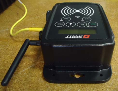
Click to zoom
Application Details
- Equipment Class
- DTS - Digital Transmission System
- Date of Grant
- Oct 27, 2013
- Application Purpose
- Original Equipment
- Date of Application
- Sep 29, 2013
- Equipment Note
- Queue Interface
- Frequency Range
- 2405.00000000 - 2405.00000000
- Country
- United States
Documents & Files
Document Text
Text extracted from the exhibit documents filed with the FCC. Open a document above to read the original.
Users Manual
Page 1 of 12 P/N 595284-01 Rev A 9/13 OPERATION AND MAINTENANCE INSTRUCTIONS SCOTT CONNECT QUEUE Interface Accessory DESCRIPTION The SCOTT CONNECT QUEUE Interface Accessory provides a log-in interface for SCOTT IMPERIUM Accountability System users that can be associated with a particular vehicle (such as a fire truck) at an event where accountability of participating personnel is required. By swiping a SCOTT Accountability System programmed ID Badge, Tag, or Button, the ID’s of up to twelve (12) users can be stored and downloaded to the Accountability System Base Station. The SCOTT CONNECT QUEUE Interface Accessory is ONLY compatible with an Accountability System Base Station that is using either a PCMCIA Gateway, SCOTT P/N 200732-02, or a USB Gateway, SCOTT P/N 201088-02 with the IMPERIUM Accountability Software. Resources who are not using a properly equipped SCOTT SCBA respirator may be added to the system for accountability purposes by using SCOTT Programmable ID Tags with either the QUEUE Interface or an RFID TAG READER/WRITER accessory. Resources added this way will not automatically be able to receive communications from the system. Special consideration must be given to resources who appear on the system using one of these methods. The Base Station Operator must verify that all personnel who appear as logged into the QUEUE Interface Accessory are actually present at the event. When activated, the SCOTT CONNECT QUEUE Interface Accessory appears on the SCOTT IMPERIUM Accountability Software Base Station Display as the identification name of the vehicle. The QUEUE Interface Accessory then downloads to the base station the ID information of all participants who have logged into the unit. When these individuals are included in the event activities, they appear on the Tactical Display Screen much like a SEMS II PDA user, except that the user details such as Air Pressure will not display. The SCOTT CONNECT QUEUE Interface Accessory can be placed up to seven tenths (0.7) mile line-of-sight from the base station. When logged on, all the SEMS II Personal Distress Alarms (PDA’s) Portable Units communicate to the Base Station directly and/or through other logged on units forming a communications “mesh network” to the Base Station. The SCOTT CONNECT QUEUE Interface Accessory extends the range for the PDA’s by providing another network location to communicate with the Base Station. Because of this mesh network system, the signal strength of each user as displayed on the Base Station may change as the network constantly re-adjusts to the movement of the users. For identification purposes, the SCOTT CONNECT QUEUE Interface Accessory comes factory programmed with an eight digit ID number that will be displayed. This default number can be reprogrammed. Refer to the UPDATE QUEUE Interface ID section of this instruction for details. © 2013 Scott Safety. SCOTT, the SCOTT SAFETY Logo, Scott Health and Safety, SEMS, IMPERIUM, and QUEUE are registered and/or unregistered marks of Scott Technologies, Inc. or its affiliates. WARNING THE SCOTT ACCOUNTABILITY SYSTEM IS INTENDED FOR USE WITH PROPERLY EQUIPPED SCOTT SELF-CONTAINED BREATHING APPARATUS (SCBA) WHICH MAY SUPPORT HUMAN LIFE IN HAZARDOUS ATMOSPHERES. FAILURE TO CAREFULLY READ AND UNDERSTAND THE FOLLOWING INSTRUCTIONS MAY RESULT IN SERIOUS INJURY OR DEATH TO THE SCBA USER. USE OF THE SCOTT CONNECT QUEUE INTERFACE ACCESSORY WILL REQUIRE MODIFICATION OF THE RESPIRATOR "REGULAR OPERATIONAL INSPECTION PROCEDURES" AND WILL REQUIRE TRAINING OF THE RESPIRATOR USER IN THE USE OF SUCH EQUIPMENT. THE FOLLOWING INSTRUCTIONS SUPPLEMENT BUT DO NOT REPLACE THE OPERATING AND MAINTENANCE INSTRUCTIONS SUPPLIED WITH EACH RESPIRATOR. CAUTION ONLY THE -02 VERSIONS OF THESE SCOTT GATEWAYS WILL OPERATE WITH THE IMPERIUM SOFTWARE AND PROVIDE FULL FUNCTIONALITY OF THE SYSTEM FEATURES AND THE QUEUE INTERFACE ACCESSORY. DO NOT USE WITH THE -01 VERSIONS OF THESE ITEMS. IF YOU HAVE THE -01 VERSIONS OF THESE GATEWAYS, CONTACT SCOTT OR YOUR SCOTT DISTRIBUTOR FOR DETAILS. WARNING SPECIAL CONSIDERATION MUST BE GIVEN TO RESOURCES WHO APPEAR ON THE SYSTEM USING ONE OF THE TAG READING METHODS. THE BASE STATION OPERATOR MUST VERIFY THAT ALL PERSONNEL WHO APPEAR AS LOGGED INTO THE QUEUE INTERFACE ACCESSORY ARE ACTUALLY PRESENT AT THE EVENT. FAILURE TO DO SO MAY RESULT PRESENTATION OF INACCURATE INFORMATION WHICH COULD LEAD TO SERIOUS INJURY OR DEATH. Page 2 of 12 P/N 595284-01 Rev A 9/13 INSTALLATION OF THE SCOTT ACCOUNTABILITY SYSTEM QUEUE INTERFACE ACCESSORY The QUEUE Interface Accessory, SCOTT P/N 201211-01, must be properly installed and powered to operate correctly. If you have any questions about installing the QUEUE Interface assembly, consult a qualified electrician before proceeding. 1. Choose a suitable location for the QUEUE Interface Accessory: a) Mount the assembly will be readily accessible but will not pose a hazard to occupants of the vehicle. b) Choose a location where the QUEUE Interface Accessory will not be exposed to excess moisture. c) The mounting surface should be flat so that tightening the mounting screws will not bend or stress the back plate of the QUEUE Interface. 2. Place the QUEUE Interface Accessory in the desired position and mark the six (6) mounting holes through the two mounting tabs on the housing. WARNING WHEN INSTALLING WITHIN A VEHICLE, DO NOT MOUNT THE QUEUE INTERFACE ACCESSORY IN A LOCATION WHERE IT MAY PRESENT A HAZARD TO OCCUPANTS OF THE VEHICLE. FAILURE TO PROPERLY LOCATE AND PROPERLY MOUNT THE QUEUE INTERFACE ASSEMBLY MAY RESULT IN SERIOUS INJURY. CONNECT THE POWER (TWO VERSIONS) UNIVERSAL POWER CORD (CONNECT TO POWER SUPPLY) HARD WIRE POWER CORD (CONNECT TO VEHICLE 12V or 24V POWER) 3. When installed in a vehicle, the QUEUE Interface Accessory must be securely mounted in either a vertical or horizontal position using the mounting holes pro- vided. Use #10 flat head machine screws in a minimum of four (4) of the holes (two on each end). Rec…
Text truncated - open the document above for the full version.
Cover Letter(s)
Authority to Act as Agent Date: June 7, 2013 American Certification Body, Inc. 6731 Whittier Avenue Suite C110 McLean, VA 22101 To Whom It May Concern: Thomas T. Smith, Ryan Urness and Amanda Hauck of LS Research, LLC is authorized to act on our behalf, until otherwise notified, for applications to American Certification Body, Inc. (ACB). We certify that we are not subject to denial of federal benefits, that includes FCC benefits, pursuant to Section 5301 of the Anti-Drug Abuse Act of 1988, 21 U.S.C. 862. Further, no party, as defined in 47 CFR 1.2002 (b), to the application is subject to denial of federal benefits, that includes FCC benefits. The term of this Agency Agreement shall start on the above date of this Agreement and shall continue in force until one (1) year thereafter. Thank you, By: __________________________ _Klaus Wilkens___________ (Signature) (Print name) Title: Senior Certification Engineer__ On behalf of: _Scott Safety________________ (Company Name) Telephone: (704)291-8395________________
Cover Letter(s)
W66 N220 Commerce Court, Cedarburg, Wisconsin 53012-2636 BUS 262.375.4400 FAX 262.375.4248 www.lsr.com To: FCC / IC Regarding: FCC ID: T5E-201211 & IC: 6453A-201211 With the guidance of FCC KDB 996369 D01 Module Certification Guide v01r03, Section VII. Question 1 Answer 1 A. (File for a new FCC ID) (page 7-8) the intent of the submitted application is to gain product certification of a device containing a 127 kHz low power transmitter that also uses a previously certified 2.4 GHz module. The transmitters are less than 20 cm apart and can transmit simultaneously. The application for certification of the Scott Safety Queue Interface Model 201211 contains a 127 kHz (Low power RFID) transmitter and a 2.4 GHz module previously certified as TFB- APEXLT / 5969A-APEXLT. Testing has been performed on the 127 kHz transmitter with the 2.4 GHz module integrated into the host device. The transmitters are within 20 cm so co-location testing has been tested and reported. The co-location testing includes the 127 kHz transmitter operation while the 2.4 GHz transmitter was set into continuous transmit modulated mode. This data can be seen in submitted test report, “TR 313086 A FCCICTX V2”. Also in this test report is data supporting the continued compliance of the 2.4 GHz transmitter installed in the host with regards to spurious harmonics in restricted bands which also applies as co-location test data. Since the 127 kHz transmitter is continuously operating regardless of 2.4 GHz transmissions, test report, “TR 313086 B FCCICTX V1” contains all 127 kHz data with the addition of the 2.4 GHz spurious emissions in restricted bands as tested in host device as well as RF conducted output power verification showing continued compliance based on the original certification of TFB-APEXLT / 5969A-APEXLT. A statement from the manufacturer as well as the original report for TFB-APEXLT / 5969A-APEXLT has been submitted as pointed out in FCC KDB 996369. The submitted for the original 2.4 GHz module as well as the Scott Safety product exhibits, applications for a composite device, and RF Exposure considerations should demonstrate compliance of this device. Thank you, Thomas T. Smith VP of EMC Test Services LS Research
Cover Letter(s)
Request for Confidentiality Date: _June 6 2013_______ Subject: Confidentiality Request for: FCC ID: _T5E-201211______ IC ID: _6453A-201211_____ Pursuant to FCC 47 CRF 0.457(d) and 0.459 and IC RSP-100, Section 10, the applicant requests that a part of the subject FCC application be held confidential. Type of Confidentiality Requested Exhibit Short Term X Permanent Block Diagrams Short Term External Photos Short Term Permanent* 1 Internal Photos Short Term X Permanent Operation Description/Theory of Operation Short Term Permanent Parts List & Placement/BOM Short Term Permanent Tune-Up Procedure Short Term X Permanent Schematics Short Term Test Setup Photos Short Term Permanent* User’s Manual *Note: ______(Insert Explanation as Necessary)______ 1 - The asterisked items (*) require further justification before permanent confidentiality will be allowed. These also currently require review by the FCC under their Permit-But-Ask policy before the grant is issued and can delay completion of an application. Further justification should be added to the note above. One such example for a potted device would be: “The EUT is FULLY potted using a non-removable epoxy based material. Removal of potting material causes irreparable damage to internal circuitry. See photographs exhibits that outline the device before and after potting.” Scott Safety has spent substantial effort in developing this product and it is one of the first of its kind in industry. Having the subject information easily available to "competition" would negate the advantage they have achieved by developing this product. Not protecting the details of the design will result in financial hardship. Permanent Confidentiality: The applicant requests the exhibits listed above as permanently confidential be permanently withheld from public review due to materials that contain trade secrets and proprietary information not customarily released to the public. Short-Term Confidentiality: The applicant requests the exhibits selected above as short term confidential be withheld from public view for a period of 180 days from the date of the Grant of Equipment Authorization and prior to marketing. This is to avoid premature release of sensitive information prior to marketing or release of the product to the public. Applicant is also aware that they are responsible to notify ACB in the event information regarding the product or the product is made available to the public. ACB will then release the documents listed above for public disclosure pursuant to FCC Public Notice DA 04-1705. NOTE for Industry Canada Applications: The applicant understands that until such time that IC distinguishes between Short Term and Permanent Confidentiality, either type of marked exhibit above will simply be marked Confidential when submitted to IC. Sincerely, By: Senior Certification Engineer Klaus Wilkens (Signature/Title) (Print name)
External Photos
EXTERNAL PHOTOS Company Name Scott Safety, Division of Scott Technologies, Inc Model # 201211 FCC ID # T5E‐201211 IC # 6453A‐201211 Page 1 of 3 EXTERNAL PHOTOS Company Name Scott Safety, Division of Scott Technologies, Inc Model # 201211 FCC ID # T5E‐201211 IC # 6453A‐201211 Page 2 of 3 EXTERNAL PHOTOS Company Name Scott Safety, Division of Scott Technologies, Inc Model # 201211 FCC ID # T5E‐201211 IC # 6453A‐201211 Page 3 of 3
ID Label/Location Info
SCOTT SAFETY A DIVISION OF SCOTT TECHNOLOGIES, INC. 4320 GOLDMINE ROAD MONROE, NORTH CAROLINA 28110 TITLE: SIZE: CAGE CODE DRAWING NO.: REV. SCALEWEIGHT LBS.SH. OF DRAWN BY: DESIGN: CHECK: PROJ. ENGR.: GROUP ENGR.: APPROVE FOR RELEASE: COMMERCIAL RESTRICTIVE LEGEND – ALL ITEMS, ASSEMBLIES, SPECIFICATIONS AND DIMENSIONS INCLUDED ON THIS DRAWING ARE PROPRIETARY TO AND THE PROPERTY OF SCOTT TECHNOLOGIES INC. AND MAY NOT BE USED TO MANUFACTURE OR DUPLICATE THE ITEMS SHOWN HEREON, THE CONTENTS OF THIS DRAWING IN WHOLE, OR IN PART, ARE NOT TO BE USED, REPRODUCED, OR DISCLOSED TO ANY THIRD PARTY WITHOUT OBTAINING THE EXPRESS WRITTEN AUTHORIZATION OF SCOTT TECHNOLOGIES, INC. REVISIONS RELEASED PER ECN # 144169 REV.DATEAPPROVEDDESCRIPTION DWG NO.SHREV NEXT ASSY FINAL ASSY DATE B15927 NOTES: 1 to 1 1 1 D. PEARL C.PARKULO 31002880 SHOWN TWICE SIZE FOR CLARITY A C131002880 3/18/13 C 3/18/13 A. CARVER3/18/13 D PEARL 3.500 2.625 .12 R TYP NOTICE THIS DOCUMENT OR INFORMATION CONTAINED WITHIN THIS DOCU- MENT RESIDES WITH A CERTIFYING AGENCY. CONTACT SCOTT’S CERTIFICATION GROUP BEFORE REVISING THIS DOCUMENT OR ANY DOCUMENTATION SPECIFIED WITHIN THIS DOCUMENT. 3/18/13 3/18/13 D. PEARL LABEL P/N 31002880 Rev C 9/13 SCOTT SAFETY Monroe, NC USA Model: 201211 Queue Interface P/N 201211-01 FCC ID: T5E-201211 IC: 6453A-201211 This device complies with Part 15 of the FCC Rules and Industry Canada requirements.Operation is subject to the following two conditions: (1) This device may not cause harmful interference, and (2) this device must accept any interference received, including interference that may cause undesired operation. 2.00 .060 .50 AREA FOR SERIAL NUMBER LABEL 31002881 (PRINTED AT SCOTT) 1. MATERIAL: .005 NOMINAL THICK POLYESTER, SUBSURFACE PRINTED, GLOSSY FINISH WITH PERMANENT PRESSURE SENSITIVE ADHESIVE ON BACK AND WITH PROTECTIVE BACKING SHEET COVERING ADHESIVE. WHITE BACKGROUND WITH TEXT TO BE BLACK. ALL LETTERS AND SYMBOLS ARE TO BE CLEAR AND DISTINGUISHABLE. CONSTRUCTION TO BE OF THE DESTRUCTIBLE TYPE SO THAT AFTER 24 HOURS IN CONTACT WITH THE SURFACE TO WHICH IT IS AFFIXED, REMOVAL WILL RESULT IN DELAMINATION AND/OR DESTRUCTION PREVENTING UNAUTHORIZED TRANSFER OF PLATE. 2. SUPPLIER IS REQUIRED TO USE FULL SIZE FILM POSITIVE APPROVED BY SCOTT. 3. FOR EASE OF APPLICATION PLATES MAY BE SUPPLIED IN EITHER OF THE FOLLOWING WAYS: A) INDIVIDUALLY WITH ONE SPLIT IN PROTECTIVE BACKING SHEET. B) INDIVIDUALLY WITH PLATE STOCK DIE CUT FROM EXCESS MARGIN. LABEL, FCC, VEHICLE REPEATER, SEMS II REVISED PER ECN # 144355B5/14/13 D. PEARL REVISED PER ECN # XXXXXX ADD MODEL NO. C8/27/13 D. PEARL
ID Label/Location Info
201211
Internal Photos
INTERNAL PHOTOS Company Name Scott Safety, Division of Scott Technologies, Inc Model # 201211 FCC ID # T5E‐201211 IC # 6453A‐201211 Page 1 of 6 INTERNAL PHOTOS Company Name Scott Safety, Division of Scott Technologies, Inc Model # 201211 FCC ID # T5E‐201211 IC # 6453A‐201211 Page 2 of 6 INTERNAL PHOTOS Company Name Scott Safety, Division of Scott Technologies, Inc Model # 201211 FCC ID # T5E‐201211 IC # 6453A‐201211 Page 3 of 6 Front of board with RFID section Close up of front side RFID section INTERNAL PHOTOS Company Name Scott Safety, Division of Scott Technologies, Inc Model # 201211 FCC ID # T5E‐201211 IC # 6453A‐201211 Page 4 of 6 Back of board with RFID section Close up of back side RFID section INTERNAL PHOTOS Company Name Scott Safety, Division of Scott Technologies, Inc Model # 201211 FCC ID # T5E‐201211 IC # 6453A‐201211 Page 5 of 6 Front side of board with Apex LT Module Close up of Apex LT module with shield removed INTERNAL PHOTOS Company Name Scott Safety, Division of Scott Technologies, Inc Model # 201211 FCC ID # T5E‐201211 IC # 6453A‐201211 Page 6 of 6 Back side of board with Apex LT module
Internal Photos
Page 1 of 9 LS Research, LLC Apex LT Module FCC ID#: TFB-APEXLT Photo One – Internal Shield Removed - #1 Page 2 of 9 LS Research, LLC Apex LT Module FCC ID#: TFB-APEXLT Photo Two – Internal Shield Removed - #2 Page 3 of 9 LS Research, LLC Apex LT Module FCC ID#: TFB-APEXLT Photo Three – Internal Shield Removed #3 Page 4 of 9 LS Research, LLC Apex LT Module FCC ID#: TFB-APEXLT Photo Four – Internal Shield Removed - #4 Location of PCB Antenna Page 5 of 9 LS Research, LLC Apex LT Module FCC ID#: TFB-APEXLT Photo Five – Internal Shield Removed - #5 Page 6 of 9 LS Research, LLC Apex LT Module FCC ID#: TFB-APEXLT Photo Six – Internal Shield Removed - #6 Page 7 of 9 LS Research, LLC Apex LT Module FCC ID#: TFB-APEXLT Photo Seven – Internal View of Antenna Connector Page 8 of 9 LS Research, LLC Apex LT Module FCC ID#: TFB-APEXLT Photo Eight – Internal View of Nearson Antenna connected to Module Page 9 of 9 LS Research, LLC Apex LT Module FCC ID#: TFB-APEXLT Photo Nine – Internal Close Up of Antenna Connector
RF Exposure Info
1 Rich FabinaFrom: Timothy R. Johnson [[email protected]] Sent: Thursday, September 05, 2013 6:09 PM To: rich Fabina Subject: Fwd: Response to Inquiry to FCC (Tracking Number 608014) (TCB) As crazy as it sounds...Here is your answer.. You may extrapolate the limit......and for 15.209 you'll probably get < 0.001% additive power density. Then apply a PBA. Tim Date: Thu, 5 Sep 2013 17:20:13 -0400 From: <[email protected]> To: <[email protected]> Subject: Response to Inquiry to FCC (Tracking Number 608014) (TCB) X-OriginalArrivalTime: 05 Sep 2013 21:20: 13.0621 (UTC) FILETIME=[B5B0A650:01CEAA7D] X-MS-Exchange-Organization-Antispam-Report: IPOnAllowList X-MS-Exchange-Organization-SCL: -1 X-MS-Exchange-Organization-AuthS ource: SERVER7.usacb.acbcert.com X-MS-Exchange-Organiza tion-AuthAs: Anonymous X-Auto-Response-Suppress: DR, OOF, AutoReply Link to Federal Communications Commission Home Page FCC Home | Search | RSS | Updates | E-Filing | Initiatives | Consumers | Find People Office of Engineering and Technology Office of Engineering and Technology 2 Inquiry on 08/30/2013 : Inquiry: Your earliest response to this is appreciated. We have run into 2 different cases this week - where a device is co-located with a low frequency TX (i.e. around 127 kHz for on e case) that is < 300 kHz combined and another device such as: a) 2.4 GHz DTS TX or b) Cellular TX. Note the 127 kHz TX is NOT a charging device and is simply a low power TX device under 15.209. Additionally in these cases the device is obviously a mobile device and NOT portable. Currently we do not have enough informati on of hand to determine if the 127 kHz TX operates continuously or not. However regardless is it extremely low power. The concern is how to evaluate co-location MPE given there are not any limits for < 300 kHz. There is no way to sum ratios of th e power density/Limit when a limit is not specified. The KDB regarding wireless charging allows desktop extrapolation of the 300 kHz limit down to 100 kHz at a 10 cm evaluation dis tance. However this actually requires near field measurements to be made and co mpared to this limit. For portable charging devices with close ly coupled inductive techniques - this seems logical as far field measurements woul d not give a good picture for porta ble considerations. However f or a simple NON CHARGING 15.209 TX used in mobile applications - this seem s excessive. For purposes of eval uating co-located MPE for a mobile device with a simple 15.209 TX can we simply extrapolate the 300 kHz and use for purposes of evaluating the sum of MPE rations is < 1? If no t, kindly explain how to handle. Thank You, 3 Tim Johnson - ACB FCC response on 09/05/2013 It is our understanding that the exposure conditions are fo r two mobile transmitting devices , one around 127 kHz and the other in the 800 or 2450 MHz range, and there is simultaneous transm ission. Both transmitters and the host are all operating with at least 20 cm separa tion from persons to qualify for the mobile exposure limits. It is assumed that both transmitters ar e collocated in the same host. For the 127 kHz transmitter, you ma y apply the 300 kHz M PE limit to determine compliance. Since it is a 15.209 device, the maximum output power is expected to be low; therefor e, it is likely that it is ca tegorically excluded from routine MPE evaluation; therefore, you may be able to estimate the MPE and then appl y the procedures in section 7.2 of KDB 4474 98 to determine simultaneous transmission MPE compliance. Please let us know if you have issues in apply the procedures in section 7.2 of KDB 447498. Please be aware of the 127 kHz transmitter is on the TCB exclusion list. You will need to submit the specific details for the host and all transmitter information, collocation configurations, MPE compliance analysis and resu lts through a KDB inquiry to request to use PBA for TC B approval. Attachment Details: Do not reply to this message. Please select the Reply to an Inquiry Response link from the OET Inquiry System to add any additional information pertaining to this inquiry. Timothy R. Johnson, iNARTE Certif ied EMC Engineer (No. EMC-002205-NE) and Wireless Device Certification Pr ofessional (No. WDCP- 100101) Examining Engineer American Certification Body, Inc. 4 6731 Whittier Ave., C110 McLean, VA 22101 email: [email protected] alternate email: [email protected] USA direct number: 404-414-8071 USA corporate phone: 703-847-4700 USA corporate fax: 703-847-6888
RF Exposure Info
LS Research, LLC website: www.lsr.com W66 N220 Commerce Court Phone: 262-375-4400 Cedarburg, WI 53012 Exemption from Routine Evaluation Exhibit Scott Safety, A Division of Scott Technologies, Inc. FCC ID: T5E-201211 IC: 6453A-201211 LS Research, LLC website: www.lsr.com W66 N220 Commerce Court Phone: 262-375-4400 Cedarburg, WI 53012 Output Power Evaluation. Evaluation Frequency = 127 kHz and 2.405 GHz Device Operation separation distance: >20cm Radiated Field Strength @ 127 kHz = 88.78 dBμ V/m @ 3m Maximum Effective Isotropic Radiated Power (mW) = Radiated field strength (dBμ V/m @ 3m - 95.2) * log -1 (EIRP(dBm)/10) = 0.226 mW 15.209 Transmitter at 127 kHz: FCC ID: TFB-APEXLT IC: 5969A-APEXLT 2.4 GHz Transmitter Power Density at 20 cm: 0.031530 mW/cm 2 / 1.0 mW/cm 2 (limit) = 0.031530 127 kHz transmitter .000045 mW/cm 2 / 100 mW/cm 2 (limit) = 0.00000045 Simultaneous Transmission MPE Sum: 0.031530 + 0.00000045 = 0.031530 mW/cm 2 < 1.0 LS Research, LLC website: www.lsr.com W66 N220 Commerce Court Phone: 262-375-4400 Cedarburg, WI 53012 The following method is recommended to demonstrate compliance with the requirements of RSS-102 for the situation described: 1) At 20 cm, the measurements will be in the near field for the 127 kHz Tx. Therefore, E and H field measurements will need to be performed. SC6 limits for uncontrolled environments at 127 kHz is set at 280 V/m and 2.19 A/m for E field (RMS) and H-field (RMS), respectively. See SC6 limits in RSS-102 ( http://www.ic.gc.ca/eic/site/smt- gst.nsf/eng/sf01904.html). The measurements would be based on IEEE C95.3 standard. 2) For the 2.4 GHz, the power density value would be determined for 20 cm. SC6 limit for uncontrolled environments at 2.4 GHz is set at 10 W/m2. 3) Once the E and H field values are obtained for the 127 kHz Tx and the power density value is obtained for the 2.4 GHz Tx, the following formulas are to be applied since the two TX are transmitting simultaneously. (E-field value for 127 kHz/SC6 E-field limit)^2 + (PD value for 2.4 GHz/SC6 PD limit) = or < 1 (H-field value for 127 kHz/SC6 H-field limit)^2 + (PD value for 2.4 GHz/SC6 PD limit) = or < 1 If both values are less than unity, they are in compliance with RSS-102. Response: The 127 kHz transmitter operating under RSS-GEN Section 7.2.5 limits with maximum field strength of 88.78 dBμ V/m at 3 meters as measured over a ground plane could be considered worst case conditions and near field conditions. For ease of calculation an assumed 100 % duty cycle for the 127 kHz transmitter is used. (Actual duty cycle of 20.2 %) Given these considerations this is an extreme over estimation of actual RF Exposure. Converting the field strength of 88.78 dBμ V/m at 3 meters to E and H fields to compare to RSS-102 limits yields an extremely large margin as shown below: Condition E-Field (V/m) H-Field (A/m) Conversion of field strength of 127 kHz transmitter 0.03 .00007311 SC6 Limit 280 2.19 (Value / Limit)^2 11.5 x10 -9 1.11 x10 -9 2.4 GHz Power Density: 0.3153 W/m 2 / 10 W/m 2 (limit) = 0.03153 Sum E-Field: 11.5 x10 -9 + 0.03153 = 0.0315300115 <<< 1 Sum H-Field: 1.11 x10 -9 + 0.03153 = 0.03153000111 <<< 1
Test Report
W66 N220 Commerce Court ● Cedarburg, WI 53012 USA ● Phone: 262.375.4400 ● Fax: 262.375.4248 ● www.lsr.com Prepared For: Scott Health & Safety-Division of Scott Technologies, Inc. Name: Queue Interface Report: TR 313086 B Model: 201211 LSR: C-1700 Serial: none (engineering sample) Page 1 of 21 i. Title Page ENGINEERING TEST REPORT # 313086 B LSR Job #: C-1700 Compliance Testing of: Queue Interface Test Date(s): July 23 and August 2, 14, 21 2013 and September 3, 2013 Prepared For: Scott Safety, A Division of Scott Technologies, Inc. Attn: Craig Parkulo Monroe Corporate Center 4320 Goldmine Road Monroe, NC 28112-7355 USA This Test Report is issued under the Authority of: Adam Alger, EMC Engineer Signature: Date: 9-3-13 Test Report Reviewed by: Khairul Aidi Zainal, Senior EMC Engineer / Lab Supervisor Signature: Date: 8-23-13 Report by: Adam Alger, EMC Engineer Signature: Date: 8-23-13 This Test Report may not be reproduced, except in full, without written approval of LS Research, LLC. Prepared For: Scott Health & Safety-Division of Scott Technologies, Inc. Name: Queue Interface Report: TR 313086 B Model: 201211 LSR: C-1700 Serial: none (engineering sample) Page 2 of 21 ii. Table of Contents Table of Contents i. Title Page ................................................................................................................................... 1 ii. Table of Contents ....................................................................................................................... 2 iii. LS Research, LLC ...................................................................................................................... 3 1.0 Summary of Test Report ............................................................................................................ 4 2.0 Test Facilities ............................................................................................................................. 4 3.0 Client Information ...................................................................................................................... 5 3.1 Equipment Under Test (EUT) Information ................................................................................ 5 3.2 Product Description ................................................................................................................... 5 3.3 Modifications Incorporated In the EUT for Compliance Purposes ........................................... 5 3.4 Deviations & Exclusions from Test Specifications ................................................................... 5 3.5 Additional Information .............................................................................................................. 5 4.0 Conditions of Test ...................................................................................................................... 6 5.0 Test Equipment .......................................................................................................................... 6 6.0 Conformance Summary ............................................................................................................. 6 Appendix A – Test Equipment ............................................................................................................. 7 Appendix B – Test Data ........................................................................................................................ 8 B.1 – Radiated Emissions ............................................................................................................... 10 B.2 – AC Mains Conducted Emissions .......................................................................................... 17 B.3 – RF Conducted Output Power Verification .............................................................................. 8 Appendix C - Uncertainty Summary .................................................................................................. 19 Appendix D - References .................................................................................................................... 20 Prepared For: Scott Health & Safety-Division of Scott Technologies, Inc. Report: TR 313086 B LSR: C-1700 iii. LS Research, LLC As an EMC Testing Laboratory, our Accreditation and Assessments are recognized through the following: A2LA – American Association for Lab Accreditation based on ISO/IEC 17025: 2005 A2LA Certificate Number: 1255.01 Federal Communications Commission (FCC) Listing of 3 Meter Semi-Anechoic Chamber based on Title 47 C FCC Registration Number: 90756 Industry Canada On file, 3 Meter Semi- Anechoic Chamber based on RSS File Number: IC 3088-A On file, 3 and 10 Meter OATS based on RSS File Number: IC 3088 U. S. Conform ity Assessment Body (CAB) Validation Validated by the European Commission as a U. S. Competent Body operating under the U. S./EU, Mutual Recognition Agreement (MRA) operating under the European Union Electromagnetic Compatibi…
Text truncated - open the document above for the full version.
Contact Information
Applicant
Yuriy Litvinov(Lead EMC Engineer)
Test Firm
LS Research, LLCRyan Urness
Technical Specifications
| # | Rule Parts | Frequency Range | Power Output |
|---|---|---|---|
| 1 | 15C | 2.40 GHz - 2.40 GHz | 72.00 mW |
Other Applications from 3M Company - Scott Technologies, Inc.
T5E201122A
Oct 25, 2015X3 SEMS + BT
Equipment Class
DSS - Part 15 Spread Spectrum Transmitter
T5E200673
Oct 23, 2007Pak Link Data Logger to be used with Pak Alert
Equipment Class
DTS - Digital Transmission System
T5E200451
Oct 03, 2007Personal Alarm Safety System with transceiver
Equipment Class
DSS - Part 15 Spread Spectrum Transmitter
T5E-200427
Sep 12, 2006Emergency Alarm Transmitter
Equipment Class
DTS - Digital Transmission System
T5E-200396
Aug 07, 2006Locator
Equipment Class
DTS - Digital Transmission System