T5E200451Personal Alarm Safety System with transceiver
3M Company - Scott Technologies, Inc.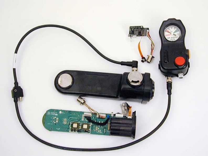
Click to zoom
Application Details
- Equipment Class
- DSS - Part 15 Spread Spectrum Transmitter
- Date of Grant
- Oct 03, 2007
- Application Purpose
- Original Equipment
- Date of Application
- Sep 24, 2007
- Equipment Note
- Personal Alarm Safety System with transceiver
- Frequency Range
- 2425.00000000 - 2425.00000000
- Country
- United States
Documents & Files
Document Text
Text extracted from the exhibit documents filed with the FCC. Open a document above to read the original.
Users Manual
Page 1 of 20 P/N 595128-01 Rev A 8/07 Copyright © 2006, SCOTT, All Rights Reserved OPERATION AND MAINTENANCE INSTRUCTIONS FOR THE SCOTT PAK-ALERT SE ® 7 DISTRESS ALARM INCLUDING THE OPTIONAL SCOTT PAK-TRACKER LOCATOR SYSTEM INTEGRATED WITH THE SCOTT AIR-PAK ® 75 or NxG7 SELF-CONTAINED BREATHING APPARATUS (SCBA) WARNING THE SCOTT PAK-ALERT SE 7 DISTRESS ALARM WITH THE PAK-TRACKER LOCATOR SYSTEM IS INTENDED FOR USE WITH SCOTT SELF-CONTAINED BREATHING APPARATUS (SCBA) WHICH MAY SUPPORT HUMAN LIFE IN HAZARDOUS ATMOSPHERES. FAILURE TO CAREFULLY READ AND UN- DERSTAND THE FOLLOWING INSTRUCTIONS MAY RESULT IN SERIOUS INJURY OR DEATH TO THE SCBA USER. USE OF A RESPIRATOR EQUIPPED WITH A PAK-ALERT SE 7 DISTRESS ALARM WITH THE PAK- TRACKER LOCATOR SYSTEM WILL REQUIRE MODIFICATION OF THE RESPIRATOR "REGULAR OPERATIONAL INSPECTION PROCEDURES" AND WILL REQUIRE TRAINING OF THE RESPIRATOR USER IN THE USE OF PASS EQUIPPED RESPIRATORS. THE FOLLOWING INSTRUCTIONS SUPPLEMENT BUT DO NOT REPLACE THE OPERATING AND MAINTENANCE INSTRUCTIONS SUPPLIED WITH EACH RESPIRATOR. FIGURE 1 AIR-PAK SCBA WITH PAK-TRACKER LOCATOR TRANSMITTER SPECIALLY EQUIPPED PAK-ALERT SE 7 DISTRESS ALARM ASSEMBLY PAK-ALERT SE 7 CONTROL CONSOLE ASSEMBLY SENSOR MODULE ASSEMBLY WITH OPTIONAL PAK-TRACKER LOCATOR TRANSMITTER (RED LABELS) OPTIONAL PAK-TRACKER HAND HELD RECEIVER Page 2 of 20 P/N 595128-01 Rev A 8/07 OPTIONAL PAK-TRACKER LOCATOR SYSTEM This unit may also be equipped with the optional SCOTT PAK-TRACKER Locator System as identified by the two round RED "Pak Tracker" labels on the Sensor Module. See FIGURE 2. 1 Kevlar is a registered trademark of E. I. Du Pont de Nemours, Inc. WARNING NO PERSONAL ALERT SAFETY SYSTEM, RES- PIRATOR OR COMBINATION OF PERSONAL ALERT SAFETY SYSTEM AND RESPIRATOR, BY THEMSELVES, CAN PROVIDE COMPLETE PRO- TECTION IN FIRE SITUATIONS. HOWEVER, USING AN ALARM AND A RESPIRATOR IN AC- CORDANCE WITH THE REQUIREMENTS OF AN ORGANIZED RESPIRATORY PROTECTION PROGRAM IS ONE OF THE MANY SAFETY PRE- CAUTIONS WHICH SHOULD BE TAKEN TO AVOID PERSONAL INJURY OR DEATH. WARNING USERS OF RESPIRATORS EQUIPPED WITH THE PAK-ALERT SE 7 DISTRESS ALARM MUST BE AWARE OF THE PROPER OPERATION OF THE DISTRESS ALARM. IF THE GREEN LIGHT IS NOT FLASHING NORMALLY, OR IF THE UNIT EXHIBITS ANY OTHER SIGNS OF A MALFUNC- TION WITHOUT THE USER TAKING PROPER CORRECTIVE ACTION, IT MAY LEAD TO CIR- CUMSTANCES THAT RESULT IN SERIOUS INJURY OR DEATH. WARNING DO NOT OPERATE THIS EQUIPMENT WHILE UNDER THE INFLUENCE OF DRUGS, ALCO- HOL, OR ANY MEDICATIONS OR SUBSTANCES WHICH MAY AFFECT VISION, DEXTERITY, OR JUDGMENT. USERS OF THIS EQUIPMENT MUST BE IN GOOD PHYSICAL AND MENTAL HEALTH IN ORDER TO OPERATE SAFELY. DO NOT USE THIS EQUIPMENT WHEN FATIGUE PREVENTS SAFE OPERATION. STAY ALERT WHEN OPERATING THIS EQUIPMENT. INAT- TENTION OR CARELESSNESS WHILE OPERATING THIS EQUIPMENT MAY RESULT IN SERIOUS INJURY OR DEATH. FIGURE 2 PAK-TRACKER EQUIPPED RED LABELS ON SENSOR MODULE PAK-TRACKER EQUIPPED RED LABELS ON SENSOR MODULE PAK-ALERT SE 7 DISTRESS ALARM The SCOTT PAK-ALERT SE 7 distress alarm consists of a sensor module mounted to the bottom of the respirator backframe, a pressure switch mounted between the cylinder and gauge line, and a control console mounted on the wearer’s right shoulder strap at the pressure gauge location. The SCOTT PAK-ALERT SE 7 distress alarm reaches full alarm in a total of thirty (30) seconds after detecting that the respirator user is motionless. The alarm may also be activated manually. The SCOTT PAK-ALERT SE 7 distress alarm is approved by the National Institute of Occupational Safety and Health (NIOSH) on all models of SCOTT SCBA except as specified in the limitations of use on the SCBA approval label and in the SCBA Operating and Maintenance Instructions. NIOSH certified SCBA’s are limited to a maximum weight of 35 lbs. When the PAK-ALERT SE 7 distress alarm is used with a one hour duration SCOTT SCBA, either the Kevlar 1 wrapped (SCOTT P/N 804222-01) or Carbon wrapped (P/N 804723-XX) cylinder and valve assembly must be used to keep the total weight under 35 lbs. limit. Using the PAK-ALERT SE 7 distress alarm with fiberglass wrapped one hour cylinder and valve assemblies, (SCOTT P/N 804107-01 or P/N 802827-01), will exceed 35 lbs. Installation of a SCOTT PAK-ALERT SE 7 distress alarm on a SCOTT AIR- PAK SCBA requires some disassembly of the respirator. Installation instructions are included with the field installation kit available from your SCOTT distributor or from SCOTT HEALTH AND SAFETY. The PAK-ALERT SE 7 distress alarm is a PERSONAL ALERT SAFETY SYS- TEM (PASS) intended to assist in locating a respirator user who is incapacitated or in need of assistance. The SCOTT PAK-ALERT SE 7 distress alarm, P/N 200451-SERIES, is an optional accessory intended only for use on SCOTT SCBA respirators including the AIR-PAK® 75, Wireframe, and NxG7 Self- Contained Breathing Apparatus (SCBA). This line of electronic accessories is for use by fire fighters, first responders, domestic preparedness and law enforcement officers, as well as industrial and hazardous material users. DESCRIPTION Page 3 of 20 P/N 595128-01 Rev A 8/07 WARNING READ AND UNDERSTAND THIS ENTIRE MANUAL AND THE PAK-TRACKER LOCATOR SYSTEM MANUAL, P/N 595102-01. TRAINING IS REQUIRED BEFORE USE OF THIS EQUIPMENT IN A HAZARDOUS SITUATION. THE TRAINING MUST INCLUDE AN UNDERSTANDING OF THE LIMITATIONS OF THE EQUIPMENT AND HOW TO INTERPRET LOCATING INFORMATION, ALONG WITH EXTENSIVE PRACTICE WITH THE SYSTEM IN A VARIETY OF ENVIRONMENTS. USE OF THIS EQUIPMENT MUST A PART OF A COMPLETE PERSONNEL ACCOUNTABILITY SYSTEM. ALWAYS UPDATE TRAINING WITH EACH NEW PIECE OF EQUIPMENT. USE OF A PAK-TRACKER LOCATOR SYSTEM WITHOUT PROPER TRAINING MAY PLACE THE USERS AT HIGHER RISK IN DANGEROUS SITUATIONS WHICH COULD RESULT IN SERIOUS INJURY OR DEATH. WARNING THE HAND HELD RECEIVER IS A BATTERY OP- ERATED ELECTRICAL DEVICE THAT HAS NOT BEEN EVALUATED AS AN IGNITION SOURCE. THIS DEVICE IS NOT TO B…
Text truncated - open the document above for the full version.
Attestation Statements
Scott Health & Safety 4320 Goldmine Road Monroe, NC 28110 U.S.A. Fire & Security Scott Health & Safety Tele:704.291.8395 Fax: 704.291.8380 e-mail: [email protected] 10 August 2007 Federal Communications Commission 7435 Oakland Mills Road Columbia, Maryland 21046 To Whom It May Concern: We the undersigned, hereby certify that, in the case of the individual applicant, he or she is not subject to a denial of federal benefits pursuant to section 5301 of the Anti-Drug Abuse Act of 1988, 21 USC 853a or in the case of non-individual applicant (e.g., corporation, partnership or other unincorporated association), no party to the applicant is subject to a denial of federal benefit pursuant to that action. Sincerely, Klaus Wilkens Certification Engineer Tyco Fire & Security Scott Health & Safety Monroe, NC
Cover Letter(s)
Scott Health & Safety 4320 Goldmine Road Monroe, NC 28110 U.S.A. Fire & Security Scott Health & Safety Tele:704.291.8395 Fax: 704.291.8380 e-mail: [email protected] Date: 08/08/2007 Time: 14:50 To: FCC Authorization & Evaluation Division 7435 Oakland Mills Road Columbia, MD 21045-0429 From: Klaus Wilkens Phone: 704-291-8395 Certification and Regulation Engineer Fax: 704-291-8380 Applicant: Scott Health & Safety Division of Scott Technologies, Inc. EMail: [email protected] ______________________________________________________________________________________ Subject: Request for Non disclosure for FCC ID: T5E200451 To Whom It May Concern: Pursuant to 47 CFR Section 0.459, Scott Health & Safety Division of Scott Technologies, Inc. hereby requests non disclosure and confidential treatment of the following materials submitted in support of FCC certification application for FCC ID # T5E200451 a. Schematic Diagrams b. Operational Description c. Block Diagram Above materials contain trade secrets, proprietary and technical information which would customarily be guarded from competitors under 47 CFR section 0.457(d)(2). Disclosure or publication of any portion of this company confidential material to other parties could cause substantial competitive harm and provide unjustified benefits for competitors. Scott Health & Safety Division of Scott Technologies, Inc. understands that pursuant to 47 CFR section 0.457(d)(1)(ii) disclosure of the applicant and all accompanying documentation will not be made before the date of the grant. Sincerely yours, By: Klaus Wilkens Title: Certification and Regulation Engineer, Scott Health & Safety Division of Scott Technologies, Inc ____________________________________________________________________________________
Cover Letter(s)
CKC Certifications Se rvices - Confidential EP04 1 of 2 Rev 10 OK # Non-Conformity or Co mment Submitted Response Respondent / Date of Response X 1 Operation description is missing, please provide a brief description of the circuit functions of the device along with a statement describing how the device operates, is modulated and meets the requirements? Operation description provided. 9/14/07 F-Squared Laboratories X 2 The schematic diagram 31001302 shows crystal X2 and X2 without indication of the Clock frequency, Please provide a revised schematic showing the component value of X2 and X3. Revised schematic with clock frequency of X2, X3 labeled. 9/14/07 F-Squared Laboratories x 3 Original Non conformity: The Blok diagram shows the presence of PIC18F1320 which is not identified on the schematic. It appears that the pressure sensor schematics are missing. Please clarify. 9/14/07: uploaded schematic diagram, Pressure sensor 1204-503 lss 12.pdf shows a PIC16LC770, which does not provide enough detail to address the PIC18F1320 and the 8 MHz crystal in question. Please provide a schematic diagram showing the controller and crystal as identified on the block diagram. 9/20/07: uploaded schematic 31001251_b.pdf shows the device in question. However, it is labeled PIC18LF132 0 which is not consistent with PIC18F1320 as indicated in the block diagram. Please provide revised Block diagram or schematic to show matching micro controller. 9/14/07, Info provide, but still insufficient. 9/20/07: additional schematic provide, however mislabeled. 9/21/07: received revised block diagram , the controller in question is now labeled as PIC18LF1320, matching the schematic diagram. 9/14/07 F-Squared Laboratories X 4 The internal photos provided must have photos of RF circuitry with RF shielding removed. Please provide additional photograph of the last section of the RF PCB with the shield removed. Photo of PCB without RF shield was provided 9/14/07 F-Squared Laboratories X 5 Original : The external photo shows only one side of the product. In accordance with 2.1033, the following is required:“ A sufficient number of photographs to clearly show the exterior appearance, the construction, the component placement on the chassis, and the chassis assembly. The exterior views shall show the overall appearance, the antenna used with the device (if any), the controls available to the user. ” Please provide additional external photos showing all side of the product. Photo provided, showing the only bottom side of the product. 9/20/07: 8 more photos submitted showing all sides of the product. 9/14/07, 9/20/07 F- Squared Laboratories CKC Certifications Se rvices - Confidential EP04 2 of 2 Rev 10 9/14/07: The additional data shows ONLY the bottom side of the product, please provide additional photo showing the remaining four sides of the product. X 6 Form 731 Item 12 states conducted power of 80 watts. It appears that this should have been 80mW, please clarify the correct listed power. Per Karen “Form 731, Item 12 should state conducted power at 80mW / 0.080 Watts.” E. Wong has updated Item 12 to reflect 0.08 W. 9/14/07 F-Squared Laboratories X 7 Page 10 of the test report indicated the power was measured at RBW of 1 MHz, however, page 9 indicates the 6 dB BW is 1.6 MHz. Per KDB558074, power output option1 1 “ Set RBW greater than 6 dB BW of the emission” Please revise test report to reflect act ual RBW used. CKC CS notes figure 3 on page 22 indicates 1.7MHz RBW used. Revised test report shows Power measured at RBW =1.7MHz. 9/18/07 F-Squared Laboratories X 8 The report does not indicate the battery status during the test. Please provide test condition complying with 15.31(e), a fresh battery shall be used for each test. Revised test report with the statement “Fresh Battery were used for each measurement performed” 9/18/07 F-Squared Laboratories X 9 Page 17- 19, The reported peak limit in restricted band is confusing: in accordance with 15.31(b), the limit on peak radio frequency emissions is 20 dB above the maximum permitted average emission limit applicable to the equipment under test. Please clarify source of peak limit and provide updated test report demonstrating compliance with this section. Revised test report show correct limit line IAW 15.247(d)/15.209 9/18/07 F-Squared Laboratories X 10 Power Spectral Density, Page 37 of the test report, IAW KDB558074, the sweep time should be (span / 3kHz), Please provide calculation to demonstrate the Power Spectral Density was measured with the required sweep time. Sample calculation provided. 9/18/07 F-Squared Laboratories X 11 Page 13 of the test report : Please provide sample calculation to demonstrate the relationship between Maximum peak power at antenna port 63.53 mW and use based time averaged power 0.32 mW. Calculation provided to show relationship between Mak Peak power and user time base power . Although the calculation contain a slight error, should be T on / (Ton + Toff) instead of Ton / Toff. But the difference is insignificant . 9/14/07 F-Squared Laboratories
External Photos
SE7ContConFront SE7ContConBack SE7ContConTop SE7ContConBtm SE7ContConSide SE7ContConBttnSide SE7Full01 SE7Full02 SE7Full03Back SE7SensModFront SE7SensModBack SE7SensModTop SE7SensModBot SE7SensModEnd SE7SensModBatCovr
ID Label/Location Info
1 1 2 2 3 3 4 4 AA BB COMMERCIAL RESTRICTIVE LEGEND - ALL ITEMS, ASSEMBLIES, SPECIFICATIONS AND DIMENSIONS INCLUDED ON THIS DRAWING ARE PROPRIETARY TO AND THE PROPERTY OF SCOTT TECHNOLOGIES, INC. AND MAY NOT BE USED TO MANUFACTURE OR DUPLICATE THE ITEMS SHOWN HEREON. THE CONTENTS OF THIS DRAWING IN WHOLE, OR IN PART, ARE NOT TO BE USED, REPRODUCED, OR DISCLOSED TO ANY THIRD PARTY WITHOUT OBTAINING THE EXPRESS WRITTEN AUTHORIZATION OF SCOTT TECHNOLOGIES, INC. DRAWN BY SCALE DRAWING NUMBERCAGE CODE TITLE APPROVED BY DESIGNED BY SIZE REV SHEET 1 OF 1 Scott Health and Safety Monroe Corporate Center 4320 Goldmine Road Monroe, North Carolina 28110 DECIMAL ANGLE .XX .XXX ± 1/2° ± .01 ± .005 UNLESS OTHERWISE SPECIFIED: DIMENSIONS ARE IN INCHES. ALL DIMENSIONS AFTER PLATING. D. Williams D. Williams 8/1/2007 8/1/2007 Label, Barcode, Sensor 2007 2/1 B 15927 31001538 A REVISION REVECN Nr.DESCRIPTIONDATEENGINEERCHECKED A Product Release 8/1/2007 D. Williams J. Phifer NOTES: 1. MATERIAL: SCOTT P/N 10011323. 2. PRODUCTION WILL PRINT THE FOLLOWING INFORMATION IN THE AREA INDICATED BY ON THE NON-ADHESIVE SIDE. A) ASSEMBLY NAME B) ASSEMBLY PART NUMBER C) PART DASH NUMBER D) FCC ID NUMBER (T5E200451) E) IC NUMBER (6453A-200451) F) SERIAL NUMBER G) MANUFACTURE DATE H) BARCODE (SHALL CONTAIN SERIAL # AND MANUFACTURE DATE) 3) BARCODE SHALL BE PER MANUFACTURING SPECIFICATION MEP 14. SENSOR MODULE ASSY SCOTT P/N 200451-XX FCC ID T5E200451 IC: 6453A-200451 SERIAL # XXXXXXXX DATE OF MFG 08/07 2.000 REF .500 REF R.063 REF TYP
Internal Photos
Internal Photos SE7SensBd01 SE7SensBd02 SE7SensBd03 SE7SensBd04 SE7SensBd05 SE7SensBd06 SE7SensBd07 SE7SensBdBattBd01 SE7SensBdNoPot02 SE7SensBdNoPot03 SE7SensBdNoPot04 SE7SensBdNoPot05 SE7SensBdRadBd01 SE7SensBdRadBd02
Test Report
This report shall not be duplicated except in full without the written approval of F-Squared Laboratories. Reports noted as a revision replace all previously issued reports and/or antecedent report revisions issued under this job number. Form EMC007-082207 Report Number: F2LQ2803-01E Rev. 2 Page 1 of 42 Issue Date: Oct. 4, 2007 F-Squared Laboratories 16740 Peters Road Middlefield, Ohio 44062 (440) 632-5541 Fax: (440) 632-5542 For a Personal Alarm Safety System Manufacturer: Testing Laboratory: Scott Health & Safety, Division of Scott F-Squared Laboratories 4320 Goldmine Road 16740 Peters Road Monroe, North Carolina 28110 Middlefield, Ohio 44062 United States of America United States of America The Personal Alarm Safety System, model 200451-02, was tested and was found to comply with the requirements of the Federal Communications Commission outlined in the Federal Register CFR 47, Part 15.247. The product was received on June 22, 2007 and the testing was completed on Sept. 5, 2007. Certification Test Report Client: Scott Health & Safety Order Number: F2LQ2803 Model: 200451-02 Form EMC007-082207 Report Number: F2LQ2803-01E Rev. 2 Page 2 of 42 Issue Date: Oct. 4, 2007 Table of Contents Section Title Page Cover Page 1 Table of Contents 2 1 Engineering Statement 3 2 List of Measurement Instrumentation 4 3 EUT Information and Data 5 4 EUT Configuration and Cables 6 5 FCC Part 15.403(f) – Digital Modulation 7 6 FCC Part 15.31(m) – Operating Frequencies 8 7 FCC Part 15.247(a)(2) – Bandwidth 9 8 IC, RSS-Gen Issue 2 – 99% Bandwidth 10 9 FCC Part 15.247(b)(3) – Power Output 11 10 FCC Part 15.247(b)(5) – RF Safety 12 11 FCC Part 15.247(c) – Spurious Emissions 16 12 FCC Part 15.247(d) – Peak Power Spectral Density 21 13 Figures – Spectral Data Plots 22 14 Photos/Exhibits – Product Photos, Test Setups 39 Client: Scott Health & Safety Order Number: F2LQ2803 Model: 200451-02 Form EMC007-082207 Report Number: F2LQ2803-01E Rev. 2 Page 3 of 42 Issue Date: Oct. 4, 2007 1. ENGINEERING STATEMENT This report has been prepared on behalf of Scott Health & Safety, Division of Scott to provide documentation for the testing described herein. This equipment has been tested and found to comply with Part 15.247 of the FCC Rules using ANSI C63.4 2003 standards. The test results found in this test report relate only to the items tested. 1.1. Equipment Under Test: Pak Alert SE 7 Personal Alarm Safety System (P.A.S.S.) with Transceiver FCC ID T5E 200451 1.2. Trade Name: Scott Health & Safety, Division of Scott 1.3. Model: 200451-01, -02, -11, -12, -61, -62 1.4. Power Supply: Batteries - 6 AA 1.5. Applicable Rules: CFR 47, Part 15.247 1.6. Equipment Category: Radio Transceiver-DTS 1.7. Antenna: (integral) 1.8. Measurement Location: F-Squared Laboratories in Middlefield, Ohio. Site description and attenuation data are on file with the FCC's Sampling and Measurement Branch at the FCC Laboratory in Columbia, MD. 1.9. Measurement Procedure: All measurements were performed according to the 2003 version of ANSI C63.4 and recommended FCC procedure of measurement of DTS operating under Section 15.247 dated March 2005 (KDB #558074). A list of the measurement equipment can be found in Section 2. 1.10. Uncertainty Budget: Radiated Emission - Combined Uncertainty (+ or -) 2.24 dB; Expanded Uncertainty (+ or -) 4.48 dB Client: Scott Health & Safety Order Number: F2LQ2803 Model: 200451-02 Form EMC007-082207 Report Number: F2LQ2803-01E Rev. 2 Page 4 of 42 Issue Date: Oct. 4, 2007 2. LIST OF MEASUREMENT INFORMATION Equipment Type Manufacturer Model Serial Number Calibration Due Date Shield Room Shielding Resources 3 Meter 001 Feb. 13, 2008 Thermohygrometer Oakton 32230-80 001 Aug. 31, 2007 OATS Compliance Labs N/A 001 Aug. 16, 2008 Spectrum Analyzer Hewlett Packard 8591E 3520A04145 Aug. 1, 2008 Antenna 1-Chamber ETS/EMCO 3142B 9811-1330 June 29, 2009 Antenna 2-OATS Sunol Sciences JB1 A101101 June 29, 2009 Horn Antenna Emco 3115 9809-5580 Sept. 21, 2007 Horn Antenna A. H. Systems, Inc. SAS-572 237 June 15, 2008 Horn Antenna A. H. Systems, Inc. SAS-586 142 June 15, 2008 Pre-Amplifier Hewlett-Packard 8447D 2944A08445 Oct. 3, 2007 Pre-Amplifier Hewlett Packard 83006A 310A00500 Oct. 3, 2007 Active 18” Loop Antenna A.H. Systems, Inc. SAS-562B 241 July 11, 2007 Test Receiver Rohde & Schwartz ESU 1302.6005.40 100002 Nov. 11, 2007 Receiver Rohde & Schwarz Display, EASI- 0-804-8932-52; 84982/015; 849152/005 July 31, 2008 Client: Scott Health & Safety Order Number: F2LQ2803 Model: 200451-02 Form EMC007-082207 Report Number: F2LQ2803-01E Rev. 2 Page 5 of 42 Issue Date: Oct. 4, 2007 3. EQUIPMENT UNDER TEST (EUT) INFORMATION AND DATA 3.1 Test Item Condition: The equipment to be tested was received in good condition. 3.2 Testing Algorithm: For RF antenna conducted tests, the PASS was equipped with an SMA connector for connection to the measuring equipment. For radiated emissions tests, on the OATS, the PASS was equipped with integral/internal antenna and installed in a SCBA. The highest emissions were recorded in the data tables. 3.3 Radiated Emission Testing on Open Area Test Site (OATS): The EUT was tested at a distance of 3.0 meters. The emissions were maximized by rotating the table and raising/lowering the antenna mounted on a 4.0 meter mast.* Both horizontal and vertical field components were measured. The output of the antenna was connected to the input of the receiver and emissions were measured in the range 10 kHz to 25 GHz. The values up to 1GHz are quasi-peak readings made at 3.0 meters with a resolution bandwidth of 200 Hz from 9 kHz to 150 kHz, 9 kHz from 150 kHz to 30 MHz and 120 kHz from 30 MHz to 1 GHz. The measurements above 1 GHz with a resolution bandwidth of 1 MHz are average readings at a distance of 3.0 meters. The raw measurements were corrected to allow for antenna factor, cable loss and preamplifier gain. All data for radiated emissions can be found in Section 10.2. *The EUT was examined in three orthogonal positions to ensure m…
Text truncated - open the document above for the full version.
Test Setup Photos
Client: Scott Health & Safety Order Number: F2LQ2803 Model: 200451-02 Form EMC007-082207 Report Number: F2LQ2803-01E Page 38 of 41 Issue Date: Aug. 23, 2007 13. PHOTOGRAPHS/EXHIBITS – PRODUCT PHOTOS, TEST SETUPS Orthogonal Positions of Remote Control – Radiated Emissions Test on OATS: EUT on Side Client: Scott Health & Safety Order Number: F2LQ2803 Model: 200451-02 Form EMC007-082207 Report Number: F2LQ2803-01E Page 39 of 41 Issue Date: Aug. 23, 2007 Orthogonal Positions of Remote Control – Radiated Emissions Test on OATS: EUT Upright Client: Scott Health & Safety Order Number: F2LQ2803 Model: 200451-02 Form EMC007-082207 Report Number: F2LQ2803-01E Page 40 of 41 Issue Date: Aug. 23, 2007 Orthogonal Positions of Remote Control – Radiated Emissions Test on OATS: EUT on its Back TOGRAPH OF POWER SUPPLY – Whole View Client: Scott Health & Safety Order Number: F2LQ2803 Model: 200451-02 Form EMC007-082207 Report Number: F2LQ2803-01E Page 41 of 41 Issue Date: Aug. 23, 2007 Antenna Conducted Measurements
Contact Information
Applicant
Yuriy Litvinov(Lead EMC Engineer)
Technical Contact
Scott Health & Safety, Div. of Scott Tech., Inc.Craig Parkulo
[email protected]704-291-8344
4320 Goldmine Rd. · Monroe · United States
Non-Technical Contact
Scott Health & Safety, Div. of Scott Tech., Inc.Klaus Wilkens
[email protected]704-291-8395
Test Firm
F-Squared LaboratoriesJohn Harrington
Technical Specifications
| # | Rule Parts | Frequency Range | Power Output |
|---|---|---|---|
| 1 | 15C | 2.42 GHz - 2.42 GHz | 80.00 mW |
Other Applications from 3M Company - Scott Technologies, Inc.
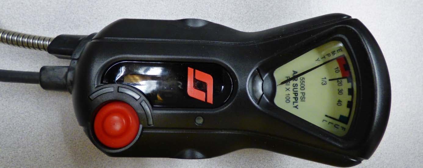
T5E201122A
Oct 25, 2015X3 SEMS + BT
Equipment Class
DSS - Part 15 Spread Spectrum Transmitter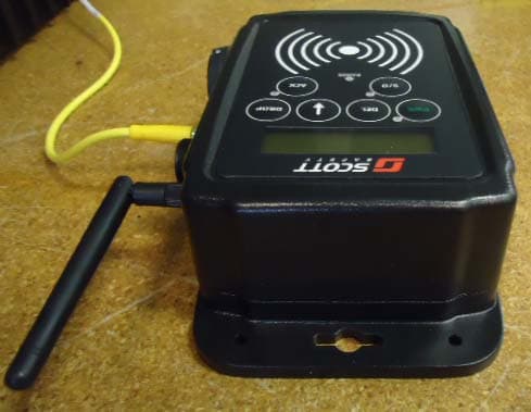
T5E-201211
Oct 27, 2013Queue Interface
Equipment Class
DTS - Digital Transmission System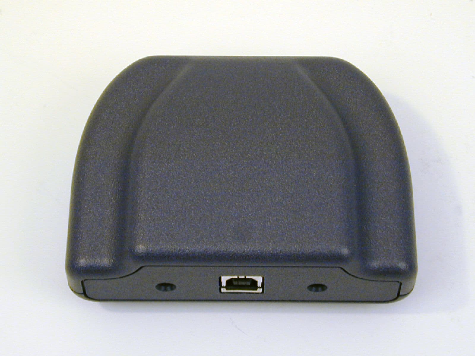
T5E200673
Oct 23, 2007Pak Link Data Logger to be used with Pak Alert
Equipment Class
DTS - Digital Transmission System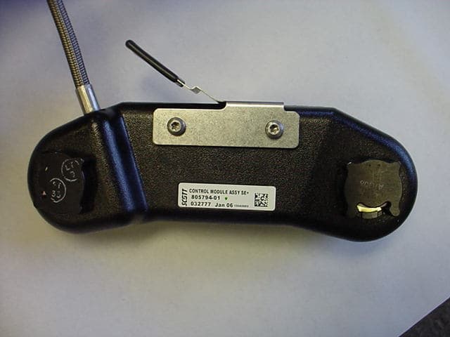
T5E-200427
Sep 12, 2006Emergency Alarm Transmitter
Equipment Class
DTS - Digital Transmission System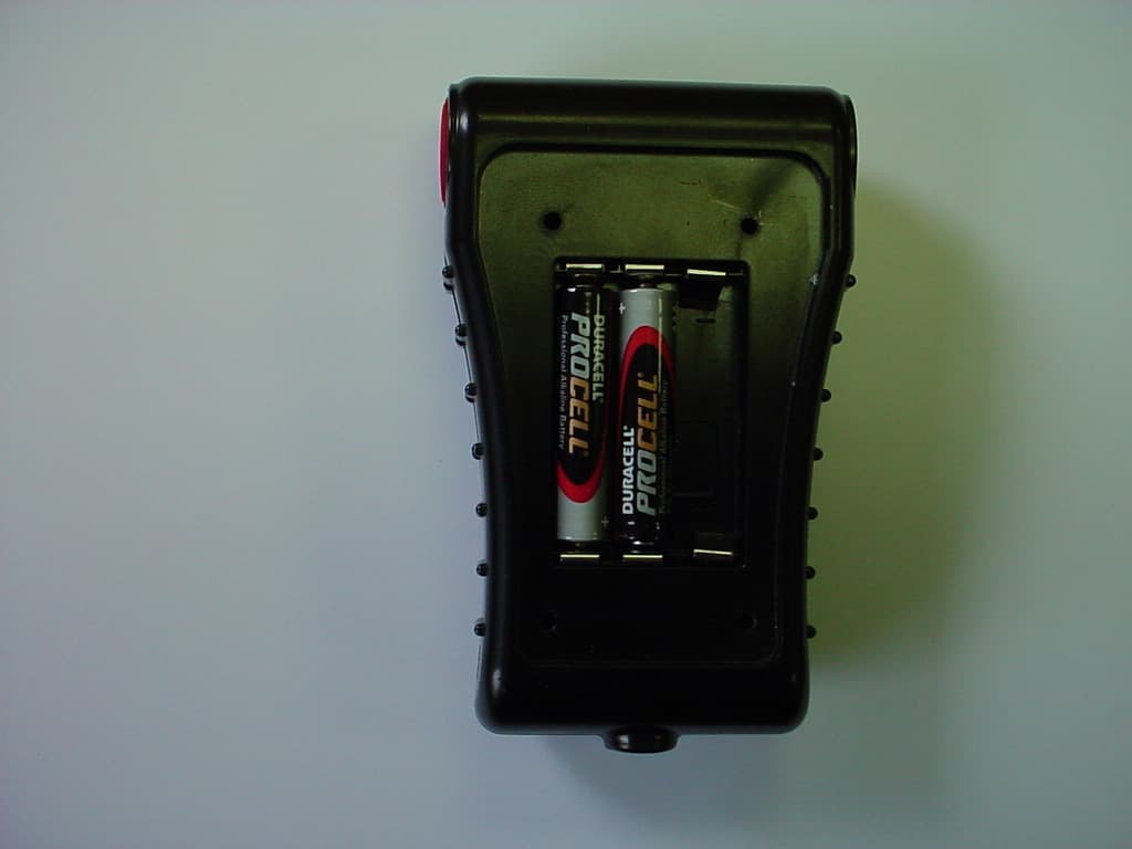
T5E-200396
Aug 07, 2006Locator
Equipment Class
DTS - Digital Transmission System