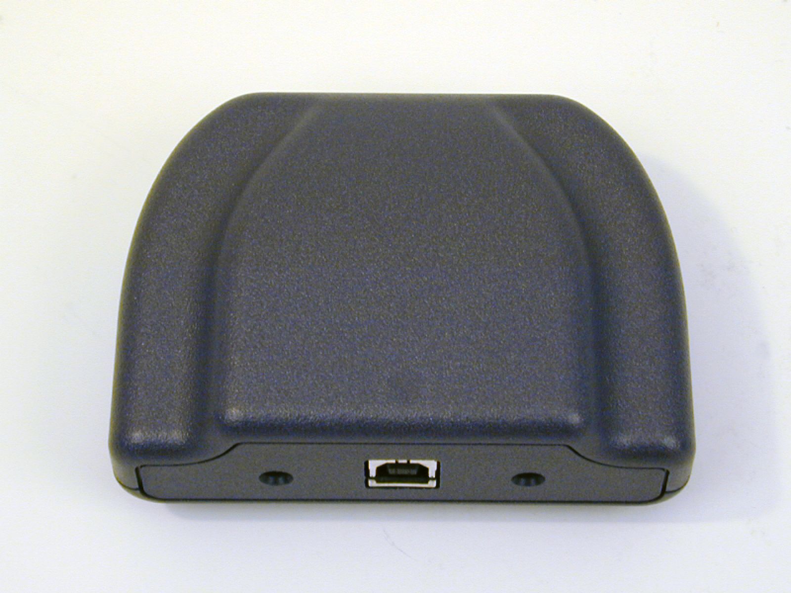
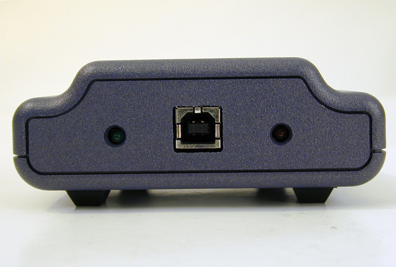
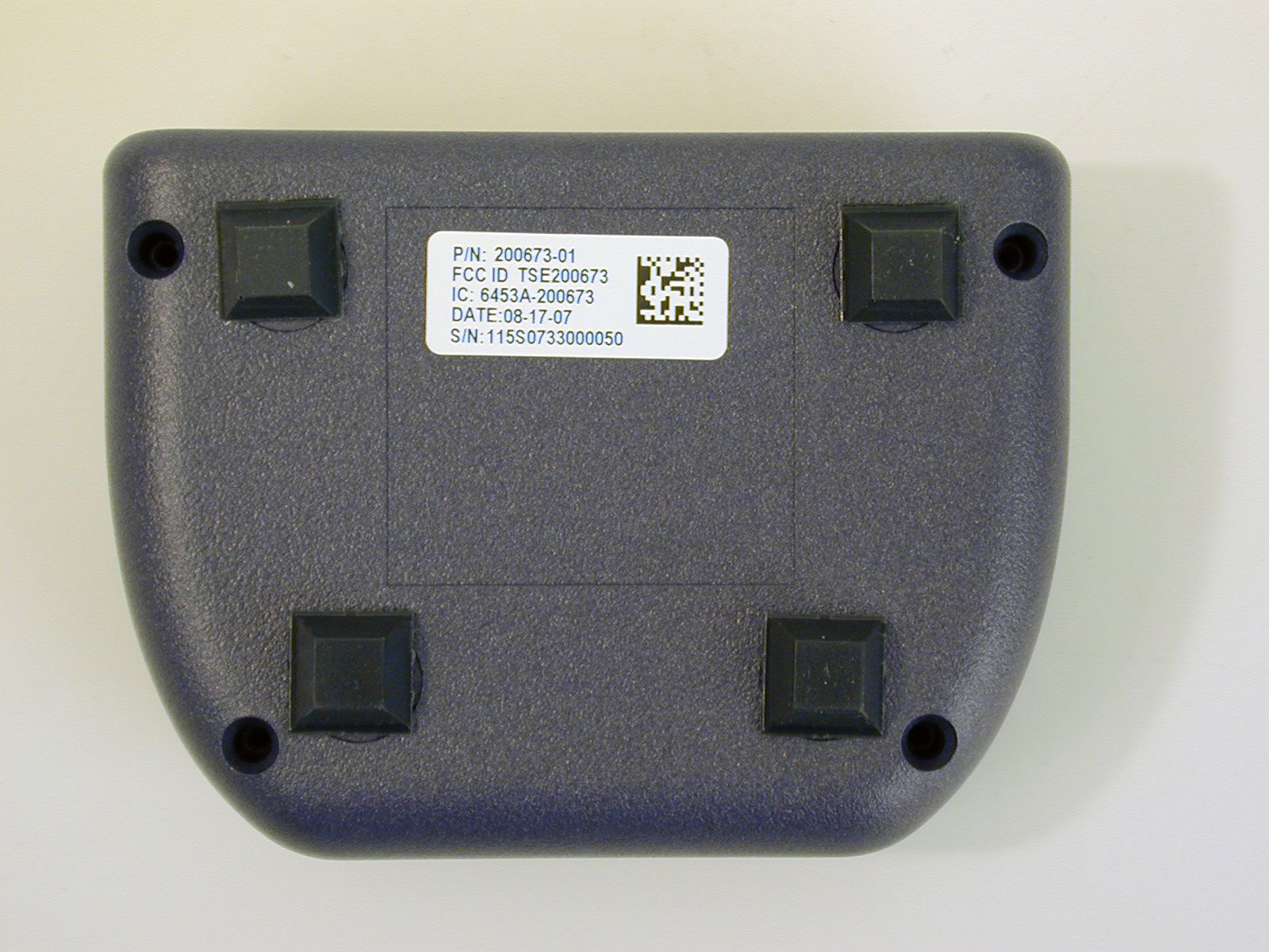
T5E200673Pak Link Data Logger to be used with Pak Alert
3M Company - Scott Technologies, Inc.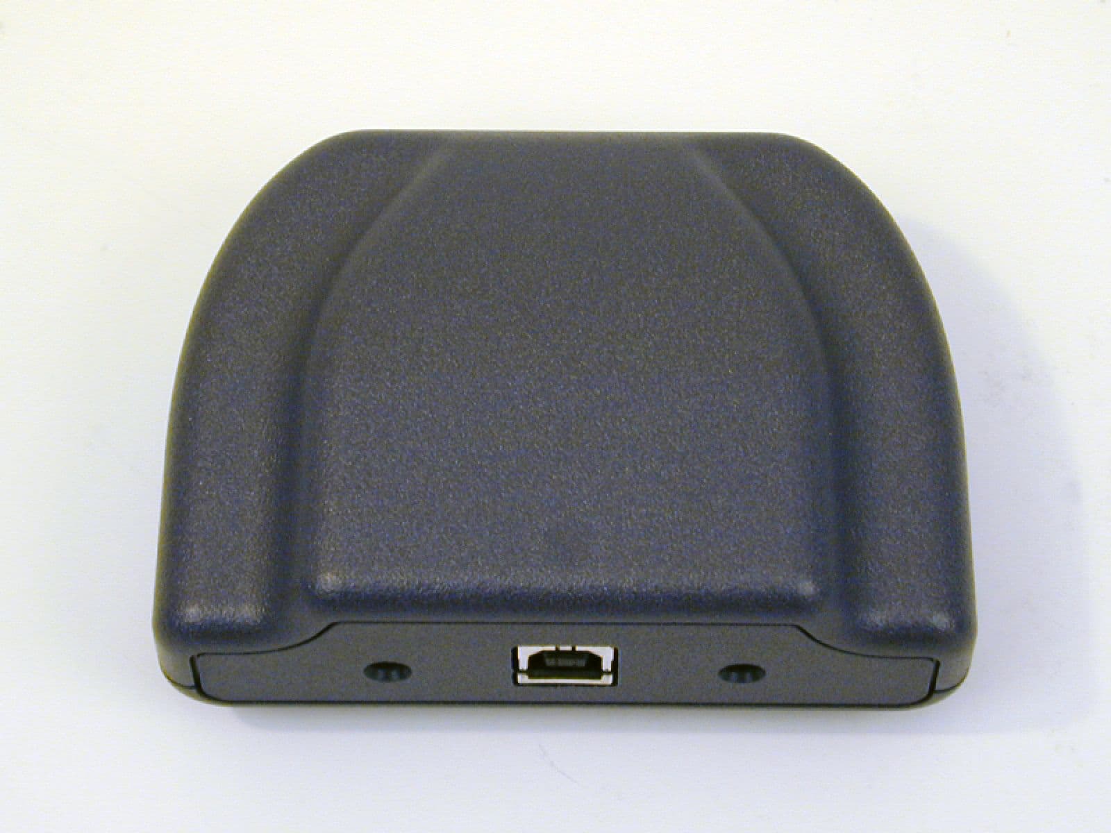
Click to zoom
Application Details
- Equipment Class
- DTS - Digital Transmission System
- Date of Grant
- Oct 23, 2007
- Application Purpose
- Original Equipment
- Date of Application
- Oct 18, 2007
- Equipment Note
- Pak Link Data Logger to be used with Pak Alert
- Frequency Range
- 2425.00000000 - 2425.00000000
- Country
- United States
Documents & Files
Document Text
Text extracted from the exhibit documents filed with the FCC. Open a document above to read the original.
Users Manual
Page 1 of 12P/N 595123-01 Rev A 9/07 INSTALLATION AND USE INSTRUCTIONS INSTALLATION AND USE INSTRUCTIONS FOR THE SCOTT PAK-LINK™ COMPUTER INTERFACE TO USE THE DATA LOGGER AND ID UPDATER FEATURES WITH PROPERLY EQUIPPED SCOTT AIR-PAK® SELF-CONTAINED BREATHING APPARATUS DATA LOGGER Software within the PAK-ALERT SE 7 distress alarm maintains a Data Log in a nonvolatile memory of a select set of events of PASS operation in the course of normal use of the respirator. The memory has a capacity of over 2000 events. When the capacity is met, new events will be written over the oldest events in the log. The events of primary use include: Off To Sensing – Date and time stamp when the PASS sensing mode is activated Sensing to Pre-Alarm – Date and time stamp when the PASS switches from the sensing mode to the pre-alarm mode Pre-Alarm To Alarm – Date and time stamp when the PASS switches from the pre-alarm mode to the alarm mode Alarm Reset – Date and time stamp when the PASS alarm mode is reset to sensing mode Manual Alarm – Date and time stamp when the PASS is manually put in alarm mode Low Battery – Date and time stamp when the PASS low power supply warning signal activates Sensing To Off – Date and time stamp when the PASS is turned to the off mode The Data Log also records certain information including Clock Reset Pending, Clock Reset, and Power On Reset. The data logging information can be downloaded by the emergency services organizations’ personnel using the PAK- LINK Computer Interface connected to a personal computer USB connection equipped with the SCOTT Data Logger Software and Microsoft ® Excel ® . The date and time in the PAK-ALERT SE 7 distress alarm Data Logger software are set initially at the factory. An internal back-up battery will maintain the date and time setting when the PASS batteries are removed or changed. However, each time the data is downloaded, the date and time on the distress alarm are automatically reset (Clock Reset) to the date and time as they appear on the personal computer. SCOTT strongly recommends that each new respirator be run through the Data Logger downloading procedure in this instruction to set the date and time to your local time zone before the unit is put into service. This procedure should also be followed if the respirator is left unused for more than six weeks. DESCRIPTION These instructions cover the following TWO software programs on SCOTT software disk P/N 31001371. PAK-LINK ID UPDATER FOR SCOTT DISTRESS ALARMS The PAK-ALERT SE 7 distress alarm comes factory programmed with an identification number unique to that unit. This is the “Device” number that appears when downloading the Data Log. This identification number can be reprogrammed to a combination of up to eight characters (letters and/or numbers) using the SCOTT PAK-LINK ID Updater Software on a personal computer with the same PAK-LINK computer interface. The SCOTT PAK-TRACKER Locator System integrated into a SCOTT PAK-ALERT Distress Alarm also uses the same ID number, so this software can be used to reprogram the ID for respirators equipped with that function as well. WINDOWS ® , Microsoft ® , and Excel ® are registered copyrights of Microsoft, Inc. Page 2 of 12P/N 595123-01 Rev A 9/07 INSTALL THE PAK-LINK COMPUTER INTERFACE USB DRIVER Before the PAK-LINK Computer Interface can be used with your computer, the USB Driver must be 2. Insert the CD disk in you computer. Installer screen will appear. See FIGURE 2. COMPUTER REQUIREMENTS The SCOTT Data Logger software is PC based and requires a minimum of WINDOWS ® 2000 or higher and a 486 or faster processor with approximately ten (10) megabytes of free disc space. The data log can be viewed within the Data Logger Software, but the computer must have Microsoft ® Excel ® installed in order to output and save a file of the data log. The Interface Unit plugs into a USB 2.0 port on the computer from which it gets its power. installed. Install the USB Driver according to the following steps: 1. Connect the PAK-LINK Computer Interface to your computer using a USB 2.0 cable. Use of a peripheral powered USB multi-port is not recommended. The GREEN Light on the PAK-LINK Computer Interface will turn on. If the GREEN light does not turn on, there is a problem with the interface. Remove the interface from service and tag for repair or replacement. FIGURE 1 GREEN LIGHT WILL TURN ON WHEN CONNECTED FIGURE 2 CAUTION THE INTERFACE UNIT GETS ITS POWER FROM THE USB PORT ON THE COMPUTER. WHEN USED WITH A BATTERY POWERED LAP TOP COMPUTER, ALWAYS UNPLUG THE USB CABLE AFTER USE TO PREVENT DRAINING THE POWER FROM THE BATTERY. Page 3 of 12P/N 595123-01 Rev A 9/07 3. Select “USB Driver” to install the USB driver on you computer needed to operate the PAK-LINK Computer Interface. Follow the instructions on the screen. See FIGURE 3. 6. Make a note of the number of the COM Port that appears. See FIGURE 4. NOTE WRITE DOWN THE COM PORT NUMBER THAT APPEARS ON YOUR SCREEN. YOU WILL NEED IT TO COMPLETE THE SETUP WHEN YOU RUN EITHER OF THE PROGRAMS 7. When your Computer displays “Found new Hardware” select OK. 4. When the USB Driver has been installed successfully, return to the Installer main screen. 5. Next to “COM Port,” click the “Refresh” button to display the COM Port that has been assigned to the USB Connection. See FIGURE 4. FIGURE 3 FIGURE 4 Page 4 of 12P/N 595123-01 Rev A 9/07 TO INSTALL DATA LOGGER SOFTWARE 1. Select “Pak-Alert Data Logger” to install the Data Logger program to download the log of events from compatible PAK-ALERT Distress Alarm PASS Device. Follow the instructions on the screen. You may need to close all other applications. See FIGURE 5. 2. When the installer creates a folder called “Scott Health & Safety” for the files, select “Continue.” 3. When the set up is completed successfully, select “OK.” You will return to the Installer screen. 4. When finished installing, close the Installer. USING THE DATA LOGGER DATE AND TIME The date and time in the PAK-AL…
Text truncated - open the document above for the full version.
Cover Letter(s)
Scott Health & Safety 4320 Goldmine Road Monroe, NC 28110 U.S.A. Fire & Security Scott Health & Safety Tele:704.291.8395 Fax: 704.291.8380 e-mail: [email protected] Date: 08/24/2007 Time: 10:05 To: FCC Authorization & Evaluation Division 7435 Oakland Mills Road Columbia, MD 21045-0429 From: Klaus Wilkens Phone: 704-291-8395 Certification and Regulation Engineer Fax: 704-291-8380 Applicant: Scott Health & Safety Division of Scott Technologies, Inc. EMail: [email protected] ______________________________________________________________________________________ Subject: Request for Non disclosure for FCC ID: T5E200673 To Whom It May Concern: Pursuant to 47 CFR Section 0.459, Scott Health & Safety Division of Scott Technologies, Inc. hereby requests non disclosure and confidential treatment of the following materials submitted in support of FCC certification application for FCC ID # T5E200673 a. Schematic Diagrams b. Operational Description c. Block Diagram Above materials contain trade secrets, proprietary and technical information which would customarily be guarded from competitors under 47 CFR section 0.457(d)(2). Disclosure or publication of any portion of this company confidential material to other parties could cause substantial competitive harm and provide unjustified benefits for competitors. Scott Health & Safety Division of Scott Technologies, Inc. understands that pursuant to 47 CFR section 0.457(d)(1)(ii) disclosure of the applicant and all accompanying documentation will not be made before the date of the grant. Sincerely yours, By: Klaus Wilkens Title: Certification and Regulation Engineer, Scott Health & Safety Division of Scott Technologies, Inc ____________________________________________________________________________________
Cover Letter(s)
Non-Conformities FCC ID : T5E200673 (CKC CS Ref # E07-000098-FCC-01) The items listed below represent requests for information following review of this application for certification under United S tates (FCC) regulations. . Further question may arise pending review of responses to these items. OK # Non-Conformity or Co mment Submitted Response Respondent / Date of Response X 1 General typographical errors: The test recorded under 15.247(c) is now really 15.247(d) – spurious emissions. 15.247(d) is now really 15.247(e) power spectral density. 15.247(b)(5) is now really 15.247(i), etc. Please make changes correspondingly throughout the test report in order to accurately reflect the test specifications effective on the date of testing. Updated test report provided F2labs 10/19/07 X 2 On page 11 of test report, the OB W measurement indicates an integrated power of 18.992mW. This power level is significantly higher than the listed power of 0.7mW under power measurements. Please explain the discrepancy. Test report indicates proper testing, as does calculation of 99% BW (provided in separate document.) Level is for reference only. F2labs 10/19/07 X 3 The internal photos provided do not show the circuitry of the transmitter section; there is an RF shield covering this portion of the PCB (see “PAK-LINK04.jpg”). Please remove RF shiled and provide addition photo(s) of this section of the board. Extra photo provided. F2labs 10/19/07 X 4 Equipment class is listed as DSS, which is reserved for FHSS type transmitters. Please confirm correct eq uipment class should be DTS (as also listed correctly in test report).. Confirmed DTS F2labs 10/19/07 X 5 Please extract test setup photos from the test report for attachment to the FCC website as a separate document. Separate exhibit provided. F2labs 10/19/07 x 6 Spurious emissions plots in figures 15 and 19 appear to have under-reported the carrier emissions presented in the da ta sheets. This is characteristic of pulsed emissions; that a single sweep of the frequency range will not capture the peak emissions of the equipment. Please confirm test procedure used to capture radiated spurious emissions; that the peak emissions were obtained correctly. The spurious emissions plots in figure 15 and 19 are pre scan / characterizations and are annotated as such. Characterization measurements are not performed on an OATS and no attempt is made to maximize the amplitude of the emissions. They do not represent formal measurements but do provide information on the frequencies of interest. F2labs 10/19/07 x 7 Please supply RF exposure statement as a separate document. Either provide MPE calculations for Mobile equipment or statement of exemption since the power output is below the low threshold. RFX information provided. F2labs 10/19/07
ID Label/Location Info
B R E A K A L L S H A R P E D G E S O N E X T E R N A L S U R F A C E S . This document was created with Win2PDF available at http://www.daneprairie.com. The unregistered version of Win2PDF is for evaluation or non-commercial use only.
RF Exposure Info
RF Exposure Statement The PAK-LINK Computer Interface (Snappy), FCC ID T5E 200673, is not body mounted. The measured peak output power level at 2.425 GHz (its only frequency of operation) is less than 1 mW. The user and/or general public will not be exposed to RF energy levels in excess of FCC guidelines, per OET Bulletin 65 Supplement C, Edition 01-01 June 2001.
Test Report
This report shall not be duplicated except in full without the written approval of F-Squared Laboratories. Reports noted as a revision replace all previously issued reports and/or antecedent report revisions issued under this job number. Form EMC007-082207 Report Number: F2LQ2830-01E Rev. 1 Page 1 of 44 Issue Date: Oct. 19, 2007 F-Squared Laboratories 16740 Peters Road Middlefield, Ohio 44062 (440) 632-5541 Fax: (440) 632-5542 For a PAK-LINK Computer Interface Manufacturer: Testing Laboratory: Scott Health & Safety, Division of Scott F-Squared Laboratories 4320 Goldmine Road 16740 Peters Road Monroe, North Carolina 28110 Middlefield, Ohio 44062 United States of America United States of America The PAK-LINK Computer Interface (Snappy) was tested and was found to comply with the requirements of the Federal Communications Commission outlined in the Federal Register CFR 47, Part 15.247. The product was received on August 17, 2007 and the testing was completed on Sept. 7, 2007. Certification Test Report Client: Scott Health & Safety Order Number: F2LQ2830 EUT: PAK-LINK Computer Interface (Snappy) Form EMC007-082207 Report Number: F2LQ2830-01E Rev. 1 Page 2 of 44 Issue Date: Oct. 19, 2007 Table of Contents Section Title Page Cover Page 1 Table of Contents 2 1 Engineering Statement 3 2 List of Measurement Instrumentation 4 3 EUT Information and Data 5 4 EUT Configuration and Cables 6 5 FCC Part 15.403(f) – Digital Modulation 7 6 FCC Part 15.31(m) – Operating Frequencies 8 7 FCC Part 15.207 – Power Line Conducted Emissions 9 8 FCC Part 15.247(a)(2) – Bandwidth 10 9 IC, RSS-Gen Issue 2 – 99% Bandwidth 11 10 FCC Part 15.247(b)(3) – Power Output 12 11 FCC Part 15.247(i) – RF Safety 13 12 FCC Part 15.247(d) – Spurious Emissions 14 13 Radiated Emissions (Restricted Bands) 15 13 FCC Part 15.247(e) – Peak Power Spectral Density 19 15 Figures – Spectral Data Plots 20 16 Photos/Exhibits – Product Photos, Test Setups 41 Client: Scott Health & Safety Order Number: F2LQ2830 EUT: PAK-LINK Computer Interface (Snappy) Form EMC007-082207 Report Number: F2LQ2830-01E Rev. 1 Page 3 of 44 Issue Date: Oct. 19, 2007 1. ENGINEERING STATEMENT This report has been prepared on behalf of Scott Health & Safety, Division of Scott to provide documentation for the testing described herein. This equipment has been tested and found to comply with Part 15.247 of the FCC Rules using ANSI C63.4 2003 standards. The test results found in this test report relate only to the items tested. 1.1. Equipment Under Test: PAK-LINK Computer Interface (Snappy) FCC ID T5E 200673 1.2. Trade Name: Scott Health & Safety, Division of Scott 1.3. Model: 200673-01 1.4. Power Supply: USB Port 1.5. Applicable Rules: CFR 47, Part 15.247 1.6. Equipment Category: Radio Transceiver-DTS 1.7. Antenna: (integral) 1.8. Measurement Location: F-Squared Laboratories in Middlefield, Ohio. Site description and attenuation data are on file with the FCC's Sampling and Measurement Branch at the FCC Laboratory in Columbia, MD. 1.9. Measurement Procedure: All measurements were performed according to the 2003 version of ANSI C63.4 and recommended FCC procedure of measurement of DTS operating under Section 15.247 dated March 2005 (KDB #558074). A list of the measurement equipment can be found in Section 2. 1.10. Uncertainty Budget: Radiated Emission - Combined Uncertainty (+ or -) 2.24 dB; Expanded Uncertainty (+ or -) 4.48 dB Client: Scott Health & Safety Order Number: F2LQ2830 EUT: PAK-LINK Computer Interface (Snappy) Form EMC007-082207 Report Number: F2LQ2830-01E Rev. 1 Page 4 of 44 Issue Date: Oct. 19, 2007 2. LIST OF MEASUREMENT INFORMATION Equipment Type Manufacturer Model Serial Number Calibration Due Date Shield Room Shielding Resources 3 Meter 001 Feb. 13, 2008 Temp/Hum. Recorder Extech RH520 H005870 Aug. 21, 2008 OATS Compliance Labs N/A 001 Aug. 16, 2008 Receiver Rohde & Schwarz Display, EASI- 0-804-8932-52; RF Unit, ESMI-RF 1032-5640-53 84982/015; 849152/005 July 31, 2008 Antenna 1-Chamber ETS/EMCO 3142B 9811-1330 June 29, 2009 Antenna 2-OATS Sunol Sciences JB1 A101101 June 29, 2009 Horn Antenna Emco 3115 9809-5580 Sept. 21, 2007 Horn Antenna A. H. Systems, Inc. SAS-572 237 June 15, 2008 Horn Antenna A. H. Systems, Inc. SAS-586 142 June 15, 2008 Transient Limiter Hewlett Packard 11947A 3107A03325 Oct. 2, 2007 Pre-Amplifier Hewlett-Packard 8447D 2944A08445 Oct. 3, 2007 Pre-Amplifier Hewlett Packard 83006A 310A00500 Oct. 3, 2007 LISN 2 Solar 8028-50-TS- 24-BNC 1128 Oct. 2, 2007 LISN 3 Solar 8028-50-TS- 24-BNC 1129 Oct. 2, 2007 Active 18” Loop Antenna A.H. Systems, Inc. SAS-562B 241 Aug. 23, 2009 Client: Scott Health & Safety Order Number: F2LQ2830 EUT: PAK-LINK Computer Interface (Snappy) Form EMC007-082207 Report Number: F2LQ2830-01E Rev. 1 Page 5 of 44 Issue Date: Oct. 19, 2007 3. EQUIPMENT UNDER TEST (EUT) INFORMATION AND DATA 3.1 Test Item Condition: The equipment to be tested was received in good condition. 3.2 Testing Algorithm: The EUT was tested at 1 carrier frequency, 2.425 GHz, the only frequency it operates at. The EUT was assessed while operating in a test mode that either provided constant modulated transmission or constant carrier wave transmission. 3.3 Conducted Emissions Testing: The EUT was placed on a 1.0 x 1.5 meter non-conductive table, 0.8 meter above a horizontal ground plane and 0.4 meter from a vertical ground plane. Power was provided to the EUT through a LISN bonded to a 3 x 2 meter ground plane. The LISN and peripherals were supplied power through a filtered AC power source. The output of the LISN was connected to the input of the receiver via a transient limiter, and emissions in the range 150 kHz to 30 MHz were measured. The measurements were recorded using the quasi-peak and average detectors as directed by the standard, and the resolution bandwidth during testing was 9 kHz. The raw measurements were corrected to allow for attenuation from the LISN, transient limiter and cables. 3.4 Radiated Emission Testing on Open Area Test Site (O…
Text truncated - open the document above for the full version.
Test Setup Photos
Scott Health & Safety F2LQ2830 Radiated Emissions Test on OATS: Front View Scott Health & Safety F2LQ2830 Radiated Emissions Test on OATS: Rear View Scott Health & Safety F2LQ2830 Conducted Measurements: Front View Scott Health & Safety F2LQ2830 Conducted Measurements: Side View
Contact Information
Applicant
Yuriy Litvinov(Lead EMC Engineer)
Technical Contact
Scott Health & Safety, Div. of Scott Tech., Inc.Craig Parkulo
[email protected]704-291-8344
4320 Goldmine Rd. · Monroe, North Carolina · United States
Non-Technical Contact
Scott Health & Safety, Div. of Scott Tech., Inc.Klaus Wilkens
[email protected]704-291-8395
Test Firm
F-Squared LaboratoriesJohn Harrington
Technical Specifications
| # | Rule Parts | Frequency Range | Power Output |
|---|---|---|---|
| 1 | 15C | 2.42 GHz - 2.42 GHz | 700.00 µW |
Other Applications from 3M Company - Scott Technologies, Inc.
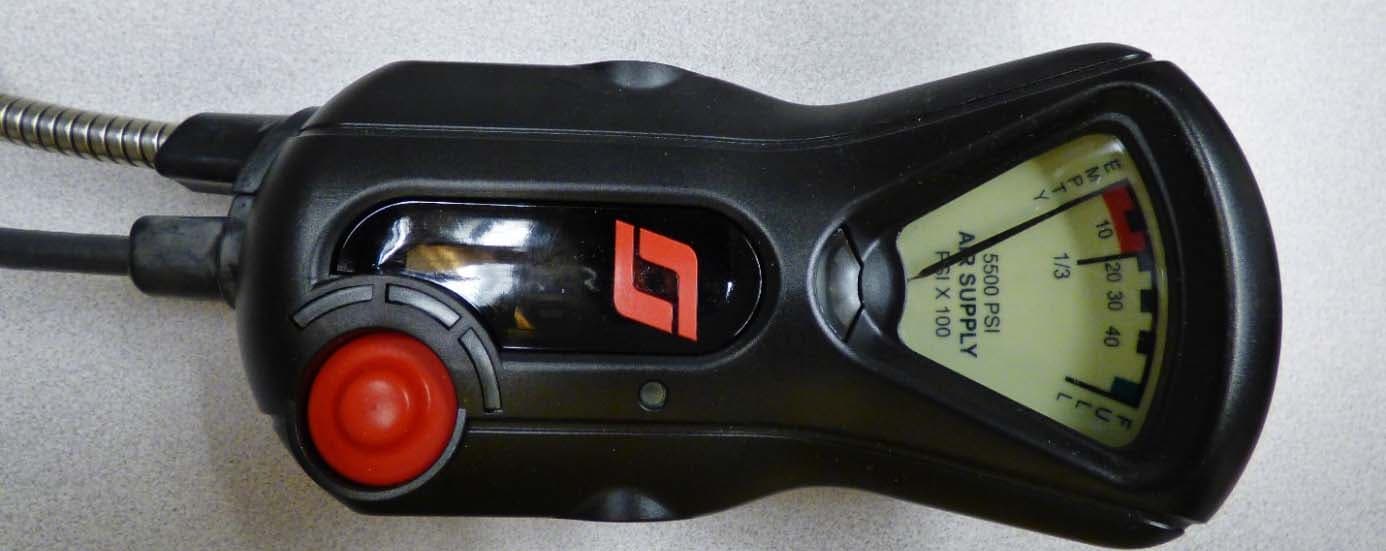
T5E201122A
Oct 25, 2015X3 SEMS + BT
Equipment Class
DSS - Part 15 Spread Spectrum Transmitter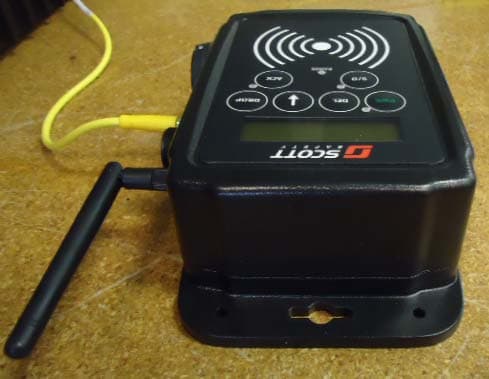
T5E-201211
Oct 27, 2013Queue Interface
Equipment Class
DTS - Digital Transmission System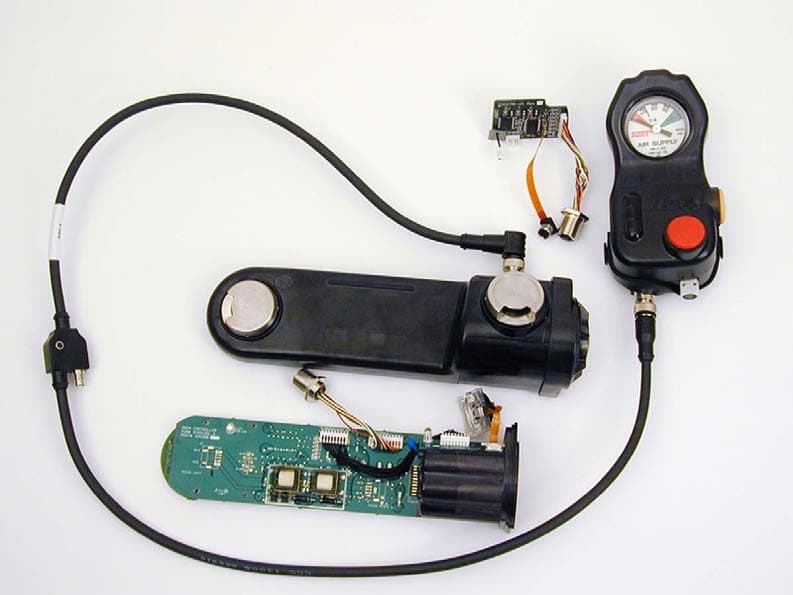
T5E200451
Oct 03, 2007Personal Alarm Safety System with transceiver
Equipment Class
DSS - Part 15 Spread Spectrum Transmitter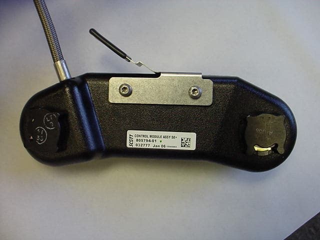
T5E-200427
Sep 12, 2006Emergency Alarm Transmitter
Equipment Class
DTS - Digital Transmission System
T5E-200396
Aug 07, 2006Locator
Equipment Class
DTS - Digital Transmission System