TSV-HHB1BASEHome Security Base Station Transceiver
Eaton Corporation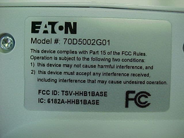
Click to zoom
Application Details
- Equipment Class
- DTS - Digital Transmission System
- Date of Grant
- Dec 21, 2005
- Application Purpose
- Original Equipment
- Date of Application
- Dec 21, 2005
- Equipment Note
- Home Security Base Station Transceiver
- Frequency Range
- 2405.00000000 - 2475.00000000
- Company
- Eaton Corporation
- Country
- United States
Documents & Files
Document Text
Text extracted from the exhibit documents filed with the FCC. Open a document above to read the original.
Users Manual
User’s Guide 3Contents Contents Introduction ..............................................................5 Getting to Know Home Heartbeat ™ ...................................7 Home Heartbeat Starter Pack Components .........................8 Getting Started .........................................................11 1. Set Up the Base Station and Home Key ™ ..................11 2. Set Up the Open/Closed Sensor ............................17 3. Place the Open/Closed Sensor .............................24 4. Set Up Remote Alerts .........................................27 5. Monitor Your Home ...........................................31 Getting the Most Out of Home Heartbeat ..........................37 Troubleshooting ........................................................47 Sensor and Component Options ....................................54 Message Glossary ....................................................58 Support ..................................................................63 © 2005 Eaton Corp. All Rights Reserved. 54 Introduction Welcome to Home Heartbeat ™ —the world’s fi rst personal wireless Home Awareness System! Home Heartbeat provides a new perspective on your home environment. The system helps you keep a watchful eye on the comfort and safety of your home. It can be extended to monitor the vital, yet often overlooked parts of your home, giving you peace of mind that all is secure. The compact, portable visual display—the Home Key ™ —organizes and presents you with the information you care about most. It can even automatically shift to alert you via your cell phone or email when you are away from home. This User’s Guide will introduce you to the Home Heartbeat system, assist you with initial setup, and explain how you can use it to monitor your home. Introduction 7 Getting to Know Home Heartbeat The Home Heartbeat Starter Pack includes the following three essential components of a Home Heartbeat system: • Base Station • Sensor • Home Key You can expand your Home Heartbeat system any time by adding additional accessories, such as more sensors or Range Extenders. (Visit www.homeheartbeat.com for more information on the latest introduction of sensors.) The next two pages provide more details about the components you will fi nd in the Home Heartbeat Starter Pack, and how they work together. This product is designed for in-home use only. Getting to Know Home Heartbeat6 89 Base Station The Base Station is the heart of the system. It communicates with the Home Keyand all sensors and accessories wirelessly and maintains constant awareness of the state of your home. Place the Base Station in a central location in your home, at least one foot away from any other wireless devices you may have. Power Adapter The power adapter allows the Base Station to be plugged into a nearby wall outlet. Home Key Use the Home Key to: • Set up the Base Station the fi rst time you use the system and set up individual sensors. • Determine whether system components are in range. • Visually monitor the status of your home while you are at home. • Get a snapshot of the current state of your home as you are leaving. • Automatically set the system to send cell phone text messages and email alerts after you have left home. Sensor Battery Each sensor is powered by one CR123A 3V lithium battery, included in the packaging. Phone Cord and Phone Cord Splitter The phone cord and splitter are included so that you can set up and receive cell phone text message and email alertswhen you are away from home.* Home Heartbeat Starter Pack Components Home Heartbeat Starter Pack ComponentsHome Heartbeat Starter Pack Components Antenna Digital Screen Thumbwheel Keychain Antenna Home Key Slide Channel Magnet Enclosed adhesive should be attached on back for placement Home KeySlide Channel Open/Closed Sensor for Doors, Windows and Cabinets This sensor monitors the state of a door, window, or cabinet, letting you know if it is open or closed. The sensor body and magnet must be installed within 1/2 inch of each other to register as closed (as shown). Sensor Body Home Key Battery Charging Contacts Red System Error Light * Note: When you plug in the Base Station, it will make an initial call to the server. The call will last less than a minute.Each time an alert is sent to your cell phone or email, the Base Station will make a quick call to the server. If your phone line is in use, Home Heartbeat will not send amessage until the line is free. Eaton does not take responsibility for the transmission time required for alerts to contact your cell phone or email, as this is regulated by your service provider. Green Charging Status Light 11 Getting Started Follow these easy steps to set up your system for the fi rst time: 1. Set Up the Base Station and Home Key 2. Set Up the Open/Closed Sensor 3. Place the Open/Closed Sensor 4. Set Up Remote Alerts 5. Monitor Your Home 1. Set Up the Base Station and Home Key Place and Power Up the Base Station The Base Station communicates with your Home Key and any sensor within range. Place it in a convenient location in your home, near a phone jack and a power outlet (for example, in your kitchen or near your bed). To avoid interference, please place the Base Station at least a foot away from any other wireless devices you may have (such as cordless phones). PLUG the power cord into the back of the Base Station and into the wall outlet.* Getting Started �� ������ ������ �������������� ������ ������������ ������ Range may vary, depending on location and home construction. 10 *For optional single receptacle and telephone surge protection, we recommend *For optional single receptacle and telephone surge protection, we recommend * using the Eaton SGXMICRONET1 Surge Strip (not included). 1213 A red light on the front of the Base Station will fl ash while the unit is starting up. When the Base Station is ready, the red light will go out, and a green light will appear. The Home Key should still be do…
Text truncated - open the document above for the full version.
Cover Letter(s)
Eaton Corporation Technology & Quality Center 170 Industry Drive, RIDC Park West Pittsburgh, PA 15275 FCC CONFIDENTIALITY Date: 11/16/2005 Time: 06:29 To: FCC Authorization & Evaluation Division 7435 Oakland Mills Road Columbia, MD 21045-0429 From: Steven G. Loughner Phone: 412 - 787 - 6560 Lead Engineer Fax: 412 - 787 - 6488 Applicant: Eaton Corporation E-Mail: [email protected] Subject: Request for Non disclosure for FCC ID: TSV – HHB1BASE. To Whom It May Concern: Pursuant to 47 CFR Section 0.459, Eaton Corporation hereby requests non disclosure and confidential treatment of the following materials submitted in support of FCC certification application for FCC ID: TSV – HHB1BASE. a. Schematic Diagrams b. Operational Description c. Block Diagram Above materials contain trade secrets, proprietary and technical information which would customarily be guarded from competitors under 47 CFR section 0.457(d)(2). Disclosure or publication of any portion of this company confidential material to other parties could cause substantial competitive harm and provide unjustified benefits for competitors. Eaton Corporation understands that pursuant to 47 CFR section 0.457(d)(1)(ii) disclosure of the applicant and all accompanying documentation will not be made before the date of the grant. Sincerely yours, By: Steven G. Loughner Title: Lead Engineer / Eaton Corporation
Cover Letter(s)
Eaton Corporation Technology & Quality Center 170 Industry Drive, RIDC Park West Pittsburgh, PA 15275 FCC A U T H O R I Z A T I O N Date: 11/14/2005 Time: 06:27 To: FCC Authorization & Evaluation Division 7435 Oakland Mills Road Columbia, MD 21045-0429 From: Steven G. Loughner Phone: 412 - 787 - 6560 Lead Engineer Fax: 412 - 787 - 6488 Applicant: Eaton Corporation E-Mail: [email protected] Dear Ladies and/or Gentlemen: I appoint Kenneth L. Boston, James Blaha and Teresa White at L.S. Compliance, Inc., to act as an agent in the preparation of applications under Part 15 of the rules and regulations of the Federal Communications Commission. I certify that the exhibitions properly describe the device being submitted under this application and will implement any changes described in the test report. The labels described will be affixed to each item. The following statement is required by the Federal Communications Commission: By checking Yes, the applicant certifies that, in the case of an individual applicant, he or she is not subject to a denial of federal benefits, that included FCC benefits, pursuant to section 5301 of the Anti-Drug Abuse Act of 1988, 21 U.S.C 853(a), or, in the case of a non- individual applicant (e.g. corporation, partnership, or other unincorporated association), no party to the application is subject to a denial of federal benefits, that includes FCC benefits, pursuant to that section. √ Yes _____No By: Steven G. Loughner Title: Lead Engineer / Eaton Corporation
External Photos
Eaton Corporation HOMEheartbeat-Whole Home Awareness System BASE STATION FCC ID#: TSV-HHB1BASE Photo One – External Front View of the Base Station Eaton Corporation HOMEheartbeat-Whole Home Awareness System BASE STATION FCC ID#: TSV-HHB1BASE Photo Two – External Rear Panel with AC Adapter Eaton Corporation HOMEheartbeat-Whole Home Awareness System BASE STATION FCC ID#: TSV-HHB1BASE Photo Three – External Back Panel with FCC ID Label Eaton Corporation HOMEheartbeat-Whole Home Awareness System BASE STATION FCC ID#: TSV-HHB1BASE Photo Four – External Close-up of FCC ID Label
Internal Photos
Eaton Corporation HOMEheartbeat-Whole Home Awareness System OC BATTERY SENSOR FCC ID#: TSV-HHB1BATR Photo One – Internal Open for Inspection Eaton Corporation HOMEheartbeat-Whole Home Awareness System OC BATTERY SENSOR FCC ID#: TSV-HHB1BATR Photo Two – Internal PCB – Battery Side and Antenna Side Eaton Corporation HOMEheartbeat-Whole Home Awareness System OC BATTERY SENSOR FCC ID#: TSV-HHB1BATR Photo Three – Internal Close-up of Chip Antenna Eaton Corporation HOMEheartbeat-Whole Home Awareness System OC BATTERY SENSOR FCC ID#: TSV-HHB1BATR Photo Four – Internal Flip Side with RF Section Shielded Eaton Corporation HOMEheartbeat-Whole Home Awareness System OC BATTERY SENSOR FCC ID#: TSV-HHB1BATR Photo Five – Internal Close-up of RF Section
RF Exposure Info
L.S. Compliance, Inc. FCC ID#: TSV-HHB1BASE Page 36 of 37 Test Report Number: 305494 TX Prepared For: Eaton Corporation 17. MPE Calculations Base Station Transceiver MPE Calculation Prediction of MPE limit at a given distance Equation from page 18 of OET Bulletin 65, Edition 97-01 where: S = power densit y P = power input to the antenna G = power gain of the antenna in the direction of interest relative to an isotropic radiator R = distance to the center of radiation of the antenna Maximum peak output power at antenna input terminal:20.00 (dBm) Maximum peak output power at antenna input terminal:100.000 (mW) Antenna gain(typi cal):0 (dBi ) Maximum antenna gain:1.000 (numeric) Prediction distance:20 (cm) Prediction frequency:2400 (MHz) MPE limit for uncontrolled exposure at prediction frequency:1 (mW/cm^2) Power density at prediction frequency:0.019894 (mW/cm^2) Maximum allowable antenna gain:17.0 (dBi) 20cm =17.0 dBMargin of Compliance at Enter data only in yellow cells 2 4R PG S π =
Test Report
L.S. Compliance, Inc. W66 N220 Commerce Court Cedarburg, WI 53012 262-375-4400 Fax: 262-375-4248 COMPLIANCE TESTING OF : HOMEheartbeat-Whole Home Awareness System Base Station Prepared For: Eaton Corporation Attn.: Mr. Richard Harwell 170 Industry Drive Pittsburgh, PA 15275 Test Report Number: 305494 TX Test Dates: November 21 st through December 2 nd , 2005 All results of this report relate only to the items that were tested. This report is not to be reproduced, except in full, without written approval of L. S. Compliance, Inc. L.S. Compliance, Inc. FCC ID#: TSV-HHB1BASE Page 2 of 37 Test Report Number: 305494 TX Prepared For: Eaton Corporation Table of Contents Section Description Page Index 1 L. S. Compliance in Review 3 2 A2LA Certificate of Accreditation 4 3 Validation Letter – U.S. Competent Body for EMC Directive 2004/108/EC (formerly 89/336/EEC) 5 4 Signature Page 6 5 Product and General Information 7 6 Introduction 7 7 Product Description 8 8 Test Requirements 9 9 Summary of Test Report 9 10 Radiated Emissions Test 10-21 11 Conducted RF Emissions Test on AC Power Line 22-26 12 Power Output 15.247 (b) 27-28 13 Spurious Emissions 15.247 (d) 29-30 14 Occupied Bandwidth 31-32 15 Spectral Density 33-34 16 Band-Edge Measurements 35 17 MPE Calculations 36 Appendix A Test Equipment List 37 L.S. Compliance, Inc. FCC ID#: TSV-HHB1BASE Page 3 of 37 Test Report Number: 305494 TX Prepared For: Eaton Corporation 1. L. S. Compliance In Review L.S. Compliance - Accreditations and Listing’s As an EMC Testing Laboratory, our Accreditation and Assessments are recognized through the following: A2LA – American Association for Laboratory Accreditation Accreditation based on ISO/IEC 17025 : 1999 with Electrical (EMC) Scope of Accreditation A2LA Certificate Number: 1255.01 Federal Communications Commission (FCC) – USA Listing of 3 Meter Semi-Anechoic Chamber based on Title 47 CFR – Part 2.948 FCC Registration Number: 90756 Industry Canada On file, 3 Meter Semi-Anechoic Chamber based on RSS-212 – Issue 1 File Number: IC 3088-A On file, 3 and 10 Meter OATS based on RSS-212 – Issue 1 File Number: IC 3088 U. S. Conformity Assessment Body (CAB) Validation Validated by the European Commission as a U. S. Competent Body operating under the U. S. /EU, Mutual Recognition Agreement (MRA) operating under the European Union Electromagnetic Compatibility –Council Directive 2004/108/EC (formerly 89/336/EEC, Article 10.2) Date of Validation: January 16, 2001 Validated by the European Commission as a U.S. Notified Body operating under the U.S./EU, Mutual Recognition Agreement (MRA) operating under the European Union Telecommunication Equipment – Council Directive 99/5/EC, Annex V. Date of Validation: November 20, 2002 Notified Body Identification Number: 1243 L.S. Compliance, Inc. FCC ID#: TSV-HHB1BASE Page 4 of 37 Test Report Number: 305494 TX Prepared For: Eaton Corporation 2. A2LA Certificate of Accreditation L.S. Compliance, Inc. FCC ID#: TSV-HHB1BASE Page 5 of 37 Test Report Number: 305494 TX Prepared For: Eaton Corporation 3. Validation Letter – U.S. Competent Body for EMC Directive 2004/108/EC (formerly 89/336/EEC) L.S. Compliance, Inc. FCC ID#: TSV-HHB1BASE Page 6 of 37 Test Report Number: 305494 TX Prepared For: Eaton Corporation 4. Signature Page Prepared By: December 12, 2005 Teresa A. White, Document Coordinator Date Tested and Approved By: December 12, 2005 Kenneth L. Boston, EMC Lab Manager Date PE #31926 Licensed Professional Engineer Registered in the State of Wisconsin, United States L.S. Compliance, Inc. FCC ID#: TSV-HHB1BASE Page 7 of 37 Test Report Number: 305494 TX Prepared For: Eaton Corporation 5. Product and General Information Manufacturer: Eaton Corporation Date(s) of Test: November 21 st through December 2 nd , 2005 Test Engineer(s): Tom Smith Abtin Spantman √ Ken Boston Model #: Base Station Serial #: Prototype Voltage: DC from either battery or a 9 VDC Wall Supply Operation Mode: Continuous Transmit 6. Introduction Between November 21 st through December 2 nd , 2005, a series of Conducted and Radiated RF Emission tests were performed on one sample of the Eaton Corporation’s HOMEheartbeat- Whole Home Awareness System Base Station, here forth referred to as the “Equipment Under Test” or “EUT”. These tests were performed using the procedures outlined in ANSI C63.4-2003 for intentional radiators, and in accordance with the limits set forth in FCC Part 15.247 (Industry Canada RSS-210) for a low power transmitter. These tests were performed by Kenneth L. Boston, EMC Lab Manager of L.S. Compliance, Inc. All Radiated and Conducted RF Emission tests were performed upon the EUT to measure the emissions in the frequency bands described in FCC Title 47 CFR, Part 15, including 15.35, 15.205, 15.247 and Industry Canada RSS-210 to determine whether these emissions are below the limits expressed within the standards. These tests were performed in accordance with the procedures described in the American National Standard for methods of measurement of Radio- Noise Emissions from Low-Voltage Electrical and Electronic Equipment in the Range of 9 kHz to 40 GHz (ANSI C63.4-2003). Another document used as a reference for the EMI Receiver specification was the Comite International Special Des Perturbations Radioelelectriques (CISPR) Number 16-1, 2003. All tests were performed at L.S. Compliance, Inc., in Cedarburg, Wisconsin, unless otherwise noted. L.S. Compliance, Inc. FCC ID#: TSV-HHB1BASE Page 8 of 37 Test Report Number: 305494 TX Prepared For: Eaton Corporation 7. Product Description This is a home security system comprised of a Base Station transceiver and numerous remote sensors. A portable display unit, shaped like an oversize key and called a fob, attaches to the base unit and provides system personalization and display/alarm capabilities. The base station may be line or battery powered. (the internal voltages are regulated such that the voltage internally is fixed regardless as to whether AC mains or the…
Text truncated - open the document above for the full version.
Test Setup Photos
Eaton Corporation Base Station Test Setup Photos Photos Taken During Radiated Emission Testing View of the EUT setup View of the EUT setup Setup for the Conducted Emissions Test
Contact Information
Applicant
Vincent Ferri(Fellow Engineer)
Test Firm
LS Research, LLCRyan Urness
Technical Specifications
| # | Rule Parts | Frequency Range | Power Output |
|---|---|---|---|
| 1 | 15C | 2.40 GHz - 2.48 GHz | 107.00 mW |
Other Applications from Eaton Corporation
TSV-SMRTRCPT
Jan 09, 2012Smart Receptacle
Equipment Class
DTS - Digital Transmission System
TSV-HHB1BBGW
Oct 01, 2006Networking Device
Equipment Class
DTS - Digital Transmission System
TSV-HHB1POWR
Jul 11, 2006Wireless Sensor
Equipment Class
DTS - Digital Transmission System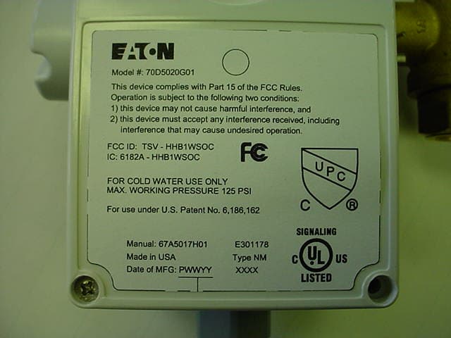
TSV-HHB1WSOC
Jul 11, 2006Monitoring Device
Equipment Class
DTS - Digital Transmission System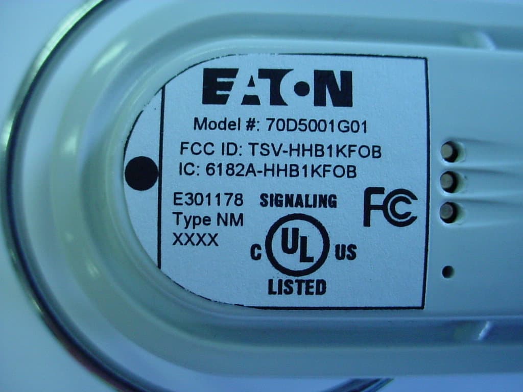
TSV-HHB1KFOB
Jun 01, 2006Controller/Monitor
Equipment Class
DTS - Digital Transmission System