TSV-SMRTRCPTSmart Receptacle
Eaton Corporation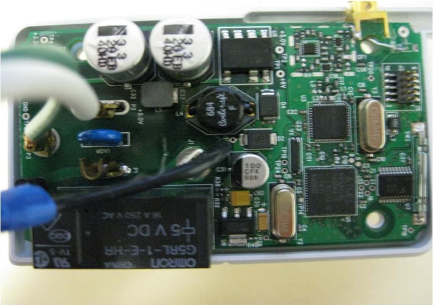
Click to zoom
Application Details
- Equipment Class
- DTS - Digital Transmission System
- Date of Grant
- Jan 09, 2012
- Application Purpose
- Original Equipment
- Date of Application
- Jan 09, 2012
- Equipment Note
- Smart Receptacle
- Frequency Range
- 2405.00000000 - 2475.00000000
- Company
- Eaton Corporation
- Country
- United States
Documents & Files
Document Text
Text extracted from the exhibit documents filed with the FCC. Open a document above to read the original.
Users Manual
Effective November 2011 Instructional Leaflet IL00406001E Eaton Smart Energy Manager Smart Receptacle Introduction The Smart Receptacle (SR) is part of the Eaton Smart Energy Manager (ESEM) system and is housed in a non-metallic enclosure. The SR plugs into any standard 120 Vac, 15A wall outlet. When a device is plugged into the SR, the SR measures, controls, and reports power consumed by that device wirelessly to the ESEM controller. • Status information and control of the SR are provided via the ESEM controller • The SR communicates wirelessly to the ESEM controller, providing load status and control capability • The SR features an LED for visual indication of operating status • The SR provides the user a three-prong receptacle rated at 120 Vac, 15A Users can monitor the power consumed by the device plugged into the SR and control power to the device remotely using the ESEM controller. Operating parameters: • 120 Vac • 15A (maximum) • Operating temperature –20° to 50°C • Humidity 10 to 95% (indoor use only) Installation procedure Step 1—Plug in Plug the SR into any 120 Vac wall outlet. Verify that the LED is on or blinking. If the LED is blinking, go to Step 3. Figure 1. Applications • Appliances • Coffee maker • Curling iron • Gaming system • Home computer • Home theater • Lighting • Microwave • Power tools • Stereo • Toaster oven • VCR Pairing channel Status LED Plug for standard grounded outlet (three-prong) Pairing key 2 Instructional Leaflet IL00406001E Effective November 2011 Eaton Smart Energy Manager Smart Receptacle EATON CORPORATION www.eaton.com Step 2—Set up Slide the “pairing key” through the pairing channel located on the top of the SR. The LED should begin to blink within 2 seconds. Refer to the ESEM controller manual for pairing setup parameters and to complete the configuration process. If the LED does not blink, repeat Step 2 or remove and re-insert the SR into the wall outlet. Figure 2. Step 3—Test and use Plug the device to be monitored and controlled into the front of the SR and turn it on. If the device does not turn on, go back to the ESEM controller and send a command to turn the device on. a LED status LED On: There is power to the device and the device is working, but the SR is not linked to the ESEM controller: 1. Place ESEM controller in join mode—refer to the ESEM controller manual for instructions. 2. Pass the pairing key through top and wait for LED to blink. 3. If LED doesn’t blink, pass the pairing key through a second time. LED Blinking: The device is working and linked to the ESEM controller. LED Off: The SR is not powered or is not operating properly. Figure 3. a For use with electrical devices requiring 120 Vac, 15A maximum. Disconnect procedure To disconnect the SR from the ESEM controller, slide the pairing key through pairing channel repeatedly until the LED stops blinking. FCC statement (Compliance Statement, Part 15.19): This device complies with Part 15 of the FCC Rules. Operation is subject to the following two conditions: (1) this device may not cause harmful interference, and (2) this device must accept any interference received, including interference that may cause undesired operation. WARNING (PART 15.21): CHANGES OR MODIFICATIONS NOT EXPRESSLY APPROVED BY THE PARTY RESPONSIBLE FOR COMPLIANCE COULD VOID THE USER’S AUTHORITY TO OPERATE THIS EQUIPMENT. TO COMPLY WITH FCC’S RF EXPOSURE LIMITS FOR GENERAL POPULATION/UNCONTROLLED EXPOSURE, THE ANTENNA(S) USED FOR THIS TRANSMITTER MUST BE INSTALLED TO PROVIDE A SEPARATION DISTANCE OF AT LEAST 20 CM FROM ALL PERSONS, AND MUST NOT BE CO-LOCATED OR OPERATING IN CONJUNCTION WITH ANY OTHER ANTENNA OR TRANSMITTER. Industry Canada statement This Device complies with Industry Canada License-exempt RSS standard(s). Operation is subject to the following two conditions: 1) this device may not cause interference, and 2) this device must accept any interference, including interference that may cause unde- sired operation of the device. Interference This equipment has been tested and found to comply with the limits for a Class B digital device, pursuant to Part 15 of the FCC rules. These limits are designed to provide reasonable protection against harmful interference in a residential installation. This equipment generates, uses, and can radiate radio frequency energy and, if not installed and used in accordance with the instructions, may cause harmful interference to radio communications. However, there is no guarantee that interference will not occur in a particular installation. If this equipment does cause harmful interference to radio or television reception, which can be determined by turning the equipment off and on, then the user is encouraged to try to correct the interference by one or more of the following measures: • Increase the separation between the SR and the receiver • Connect the SR into a power source on a different circuit from the receiver’s Smart Receptacle maintenance No serviceable parts. Clean with a soft, dry cloth. Agency certifications • ULT 916—Energy Management Equipment (PAZX) • cULT C22.2 No. 205—Signal Equipment • Federal Communications Commission—Title 47 CFR FCC, Section 15.109 • Industry Canada—RSS-210 If your Smart Receptacle... • Will not respond: Make sure that the SR is installed into a powered outlet • Does not send a signal to the ESEM controller: Refer to the configuration document for setup parameters • Does not respond to Step 2: • Select an alternate location for the SR, or • Try moving the ESEM controller to a more central location in your home. Then, complete Step 1 again
ID Label/Location Info
LABEL PLACEMENTPHOTO Company Name Eaton Corporation Model # 6D32429G01 FCC ID # TSV‐SMRTRCPT IC # 6182A‐SMRTRCPT Page 1 of 1
Internal Photos
INTERNAL PHOTOS Company Name Eaton Corporation Model # 6D32429G01 FCC ID # TSV‐SMRTRCPT IC # 6182A‐SMRTRCPT Page 1 of 2 Open for review Close up of board (front side) INTERNAL PHOTOS Company Name Eaton Corporation Model # 6D32429G01 FCC ID # TSV‐SMRTRCPT IC # 6182A‐SMRTRCPT Page 2 of 2 Close up of chip antenna Back side of board
RF Exposure Info
Prediction of MPE limit at a given distance Equation from page 18 of OET Bulletin 65, Edition 97-01 where:S = power density P = power input to the antenna G = power gain of the antenna in the direction of interest relative to an isotropic radiator R = distance to the center of radiation of the antenna Maximum peak output power at antenna input terminal:12.59 (dBm) Maximum peak output power at antenna input terminal:18.155 (mW) Antenna gain(typical):-0.5 (dBi) Maximum antenna gain:0.891 (numeric) Prediction distance:20 (cm) Prediction frequency:2400 (MHz) MPE limit for uncontrolled exposure at prediction frequency:1 (mW/cm^2) Power density at prediction frequency:0.003219 (mW/cm^2) Maximum allowable antenna gain:24.4 (dBi) 20cm =24.9 dB Margin of Compliance at 2 4R PG S 2 4R PG S
Test Report
W66 N220 Commerce Court ● Cedarburg, WI 53012 Phone: 262.375.4400 ● Fax: 262.375.4248 www.lsr.com TEST REPORT #: 310306 LSR Job #: C-1036 Compliance Testing of: Smart Receptacle Test Date(s): December 10 th , 2010 to February 27 th , 2011 and August 5 th , 2011 Prepared For: Eaton Attn: Vince Ferri 170 Industry Drive Pittsburgh, PA 15275 In accordance with: Federal Communications Commission (FCC) Part 15, Subpart C, Section 15.247 Industry Canada (IC) RSS 210 Annex 8 Digital Modulation Transmitters (DTS) This Test Report is issued under the Authority of: Khairul Aidi Zainal, Senior EMC Engineer Signature: Date: 5/11/11 Quality Assurance by: Khairul Aidi Zainal, Senior EMC Engineer Signature: Date: 5/11/11 Project Engineer: Shane D. Rismeyer, EMC Engineer Signature: Date: 5/1/11 This Test Report may not be reproduced, except in full, without written approval of LS Research, LLC. LS Research, LLC Page 2 of 52 Prepared For: Eaton Model Number: 6D32429G01 Report #: 310306 EUT: Smart Receptacle Serial Number: N/A LSR Job #: C-1036 TABLE OF CONTENTS EXHIBIT 1. INTRODUCTION ............................................................................................................. 4 1.1 - Scope .................................................................................................................................. 4 1.2 – Normative References ....................................................................................................... 4 1.3 - LS Research, LLC in Review .............................................................................................. 5 EXHIBIT 2. PERFORMANCE ASSESSMENT ................................................................................... 6 2.1 – Client Information ............................................................................................................... 6 2.2 - Equipment Under Test (EUT) Information .......................................................................... 6 2.3 - EUT’S Technical Specifications .......................................................................................... 7 EXHIBIT 3. EUT OPERATING CONDITIONS & CONFIGURATIONS DURING TESTS ................... 8 3.1 - Climate Test Conditions ...................................................................................................... 8 3.2 - Applicability & Summary of EMC Emission Test Results .................................................... 8 3.3 - Modifications Incorporated In the EUT for Compliance Purposes ...................................... 8 3.4 - Deviations & Exclusions from Test Specifications .............................................................. 8 EXHIBIT 4. DECLARATION OF CONFORMITY ................................................................................ 9 EXHIBIT 5. RADIATED EMISSIONS TEST ...................................................................................... 10 5.1 - Test Setup ......................................................................................................................... 10 5.2 - Test Procedure ................................................................................................................. 10 5.3 - Test Equipment Utilized .................................................................................................... 11 5.4 - Test Results ...................................................................................................................... 11 5.5 - Calculation of Radiated Emissions Limits ......................................................................... 12 5.6 - Radiated Emissions Test Data Chart ................................................................................ 13 5.7 - Screen Captures - Radiated Emissions Test .................................................................... 15 5.8 - Receive Mode Testing ...................................................................................................... 20 5.9 - Screen Captures - Radiated Emissions Testing – Receive Mode .................................... 21 EXHIBIT 6. CONDUCTED EMISSIONS TEST, AC POWER LINE .................................................. 25 6.1 - Test Setup ......................................................................................................................... 25 6.2 - Test Procedure ................................................................................................................. 25 6.3 - Test Equipment Utilized .................................................................................................... 25 6.4 - Test Results ...................................................................................................................... 25 6.5 - FCC Limits of Conducted Emissions at the AC Mains Ports ............................................ 26 6.6 – Conducted Emissions Test Data Chart ............................................................................ 27 6.7 - Test Setup Photo(s) – Conducted Emissions Test ........................................................... 28 LS Research, LLC Page 3 of 52 Prepared For: Eaton Model Number: 6D32429G01 Report #: 310306 EUT: Smart Receptacle Serial Number: N/A LSR Job #: C-1036 6.8 - Screen Captures – Conducted Emissions Test ................................................................ 28 EXHIBIT 7. OCCUPIED BANDWIDTH ............................................................................................. 31 7.1 - Limits ................................................................................................................................. 31 7.2 - Method of Measurements ................................................................................................. 31 7.3 - Test Equipment List .......................................................................................................... 31 7.4 - Test Data ................................................................................…
Text truncated - open the document above for the full version.
Test Setup Photos
TEST SETUP PHOTOS Company Name Eaton Corporation Model # 6D32429G01 FCC ID # TSV‐SMRTRCPT IC # 6182A‐SMRTRCPT Page 1 of 3 TEST SETUP PHOTOS Company Name Eaton Corporation Model # 6D32429G01 FCC ID # TSV‐SMRTRCPT IC # 6182A‐SMRTRCPT Page 2 of 3 TEST SETUP PHOTOS Company Name Eaton Corporation Model # 6D32429G01 FCC ID # TSV‐SMRTRCPT IC # 6182A‐SMRTRCPT Page 3 of 3
Contact Information
Applicant
Vincent Ferri(Fellow Engineer)
Technical Contact
Eaton CorporationVincent Ferri
[email protected]412 716 9471
1000 Cherrington Parkway · Moon Township, Pennsylvania · United States
Test Firm
LS Research, LLCRyan Urness
Technical Specifications
| # | Rule Parts | Frequency Range | Power Output |
|---|---|---|---|
| 1 | 15C | 2.40 GHz - 2.48 GHz | 61.00 mW |
Other Applications from Eaton Corporation
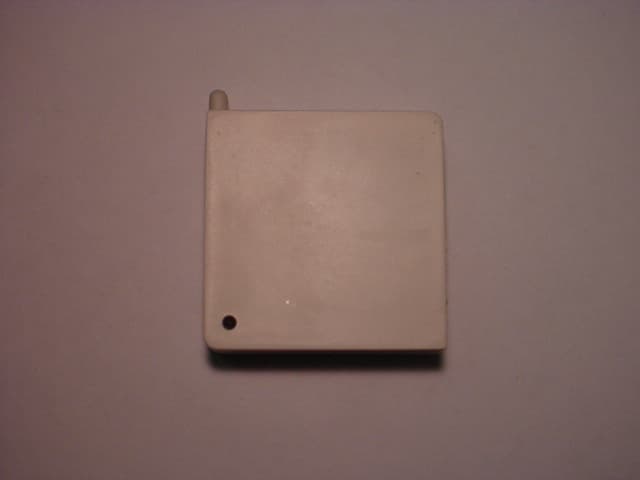
TSV-HHB1BBGW
Oct 01, 2006Networking Device
Equipment Class
DTS - Digital Transmission System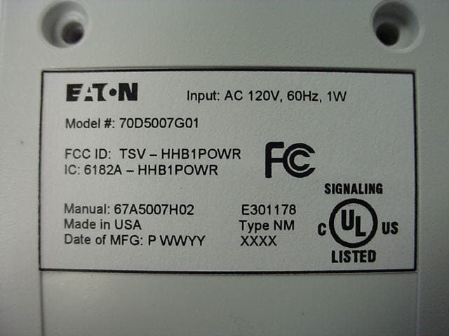
TSV-HHB1POWR
Jul 11, 2006Wireless Sensor
Equipment Class
DTS - Digital Transmission System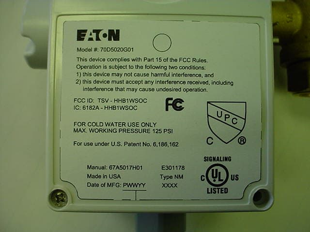
TSV-HHB1WSOC
Jul 11, 2006Monitoring Device
Equipment Class
DTS - Digital Transmission System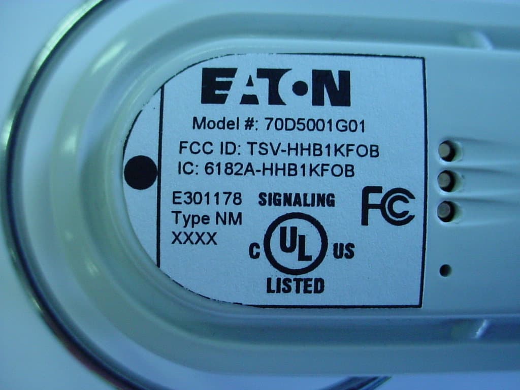
TSV-HHB1KFOB
Jun 01, 2006Controller/Monitor
Equipment Class
DTS - Digital Transmission System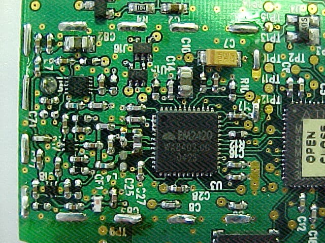
TSV-HHB1BATR
Mar 21, 2006Open/Closed Sensor
Equipment Class
DTS - Digital Transmission System