TSV-HHB1BATROpen/Closed Sensor
Eaton Corporation
Click to zoom
Application Details
- Equipment Class
- DTS - Digital Transmission System
- Date of Grant
- Mar 21, 2006
- Application Purpose
- Original Equipment
- Date of Application
- Mar 21, 2006
- Equipment Note
- Open/Closed Sensor
- Frequency Range
- 2405.00000000 - 2475.00000000
- Company
- Eaton Corporation
- Country
- United States
Documents & Files
Document Text
Text extracted from the exhibit documents filed with the FCC. Open a document above to read the original.
Users Manual
Open/Closed Sensor IM00416004E Rev. 2 Part No.: 67A5005H01 © 2005 Eaton Corporation • Garage Door • Storage Area • Basement Door • Pet Door • Refrigerator • Closet • Trunk • Deck Door • Basement Window • Kitchen Window • Safe • Supply Room • Household Cabinets • Jewelry Box • Gun Cabinet Open/Closed Sensor Uses: Open/Closed Sensor Components PMS 314 MATCH CMYK PMS 431 MATCH CMYK Home Key ™ Slide Channel Antenna Magnet Attach enclosed adhesive on back for placement FCC Statement (Compliance Statement, Part 15.19): This device complies with Part 15 of the FCC Rules. Operation is subject to the following two conditions: (1) this device may not cause harmful interference, and (2) this device must accept any interference received, including interference that may cause undesired operation. WARNING (Part 15.21): Changes or modifications not expressly approved by the party responsible for compliance could void the user’s authority to operate this equipment. To comply with FCC’s RF exposure limits for general population/uncontrolled exposure, the antenna(s) used for this transmitter must be installed to provide a separation distance of at least 20 cm from all persons and must not be co-located or operating in conjunction with any other antenna or transmitter. Industry Canada Statement The term “IC” before the certification/registration number only signifies that the Industry Canada technical specifications were met. Interference This equipment has been tested and found to comply with the limits for a Class B digital device, pursuant to Part 15 of the FCC rules. These limits are designed to provide reasonable protection against harmful interference in a residential installation. This equipment generates, uses, and can radiate radio frequency energy and, if not installed and used in accordance with the instructions, may cause harmful interference to radio communications. However, there is no guarantee that interference will not occur in a particular installation. If this equipment does cause harmful interference to radio or television reception, which can be determined by turning the equipment off and on, then the user is encouraged to try to correct the interference by one or more of the following measures: • Reorient or relocate the receiving antenna • Increase the separation between the equipment and the receiver • Connect the equipment into a power source on different circuit than the receiver. 5.625” FOLD DOES NOT PRINT DOES NOT PRINT FOLD 11” 3.625”3.6875” BLEED = .125” 3.6875” BLEED = .125”
Users Manual
Need help? Call 1-800-813-2199 for customer support or visit www.homeheartbeat.com If Your Open/Closed Sensor . . . • will not respond, make sure the battery in the sensor is installed correctly. • does not send a signal to the Base Station, move the sensor and Base Station closer together (or consider getting a Range Extender). Set upTestPlace and use Test the sensor by moving its two parts together and apart while checking the Home Key screen for feedback. (The sensor is “closed” when the two sensor parts are within 1/2 inch of each other.) ROLL OVER and highlight the Open/Closed icon on the Home Key. Take the sensor and the Home Key to the location where you want to place it. Using the Home Key, DOUBLE-CLICK at the Home Status icon and CLICK Check Ran ge? to go to the built-in Range Finder. If you are out of range, move closer to the Base Station or add a Range Extender. If the sensor is in range of the Base Station, attach one part to the edge of a door, window, or cabinet, and the other within 1/2 inch of it. Mount each part by attaching the enclosed adhesive tape to the back or by using two #4 wood screws (not included). PMS 314 MATCH CMYK PMS 431 MATCH CMYK CLICK the Home Key thumbwheel to wake the screen, then SLIDE the Home Key into the Slide Channel on the top of the sensor. Follow the instructions on the Home Key screen to join the sensor to the system, name it, and set In-Home A wareness and "CallMe" A wareness. A B REMOVE the sensor cover and insert the battery. The green LED light inside the sensor should flash four times if the battery is good. Replace the cover. A B Front Door Closed for 45mins Front Door Closed for 45mins Front Door Opened for 5mins Open/Closed Sensor Home Status Everything is OK In range Done, go back? Check Range? > 5.625” FOLD DOES NOT PRINT DOES NOT PRINT FOLD 3.6875”3.6875” 11” 3.625” BLEED = .125” BLEED = .125”
Cover Letter(s)
Eaton Corporation Technology & Quality Center 170 Industry Drive, RIDC Park West Pittsburgh, PA 15275 FCC CONFIDENTIALITY Date: 11/16/2005 Time: 06:29 To: FCC Authorization & Evaluation Division 7435 Oakland Mills Road Columbia, MD 21045-0429 From: Steven G. Loughner Phone: 412 - 787 - 6560 Lead Engineer Fax: 412 - 787 - 6488 Applicant: Eaton Corporation E-Mail: [email protected] Subject: Request for Non disclosure for FCC ID: TSV – HHB1BATR. To Whom It May Concern: Pursuant to 47 CFR Section 0.459, Eaton Corporation hereby requests non disclosure and confidential treatment of the following materials submitted in support of FCC certification application for FCC ID: TSV – HHB1BATR. a. Schematic Diagrams b. Operational Description c. Block Diagram Above materials contain trade secrets, proprietary and technical information which would customarily be guarded from competitors under 47 CFR section 0.457(d)(2). Disclosure or publication of any portion of this company confidential material to other parties could cause substantial competitive harm and provide unjustified benefits for competitors. Eaton Corporation understands that pursuant to 47 CFR section 0.457(d)(1)(ii) disclosure of the applicant and all accompanying documentation will not be made before the date of the grant. Sincerely yours, By: Steven G. Loughner Title: Lead Engineer / Eaton Corporation
Cover Letter(s)
Eaton Corporation Technology & Quality Center 170 Industry Drive, RIDC Park West Pittsburgh, PA 15275 FCC A U T H O R I Z A T I O N Date: 11/14/2005 Time: 06:27 To: FCC Authorization & Evaluation Division 7435 Oakland Mills Road Columbia, MD 21045-0429 From: Steven G. Loughner Phone: 412 - 787 - 6560 Lead Engineer Fax: 412 - 787 - 6488 Applicant: Eaton Corporation E-Mail: [email protected] Dear Ladies and/or Gentlemen: I appoint Kenneth L. Boston, James Blaha and Teresa White at L.S. Compliance, Inc., to act as an agent in the preparation of applications under Part 15 of the rules and regulations of the Federal Communications Commission. I certify that the exhibitions properly describe the device being submitted under this application and will implement any changes described in the test report. The labels described will be affixed to each item. The following statement is required by the Federal Communications Commission: By checking Yes, the applicant certifies that, in the case of an individual applicant, he or she is not subject to a denial of federal benefits, that included FCC benefits, pursuant to section 5301 of the Anti-Drug Abuse Act of 1988, 21 U.S.C 853(a), or, in the case of a non- individual applicant (e.g. corporation, partnership, or other unincorporated association), no party to the application is subject to a denial of federal benefits, that includes FCC benefits, pursuant to that section. √ Yes _____No By: Steven G. Loughner Title: Lead Engineer / Eaton Corporation
ID Label/Location Info
Material: Thermo Printable - Flexcon Matte Silver Select 22830 Adhesive: Permanent Acrylic Adhesive UL per MH12184 (UL969)
Internal Photos
Eaton Corporation HOMEheartbeat-Whole Home Awareness System OC BATTERY SENSOR FCC ID#: TSV-HHB1BATR Photo One – Internal Open for Inspection Eaton Corporation HOMEheartbeat-Whole Home Awareness System OC BATTERY SENSOR FCC ID#: TSV-HHB1BATR Photo Two – Internal PCB – Battery Side and Antenna Side Eaton Corporation HOMEheartbeat-Whole Home Awareness System OC BATTERY SENSOR FCC ID#: TSV-HHB1BATR Photo Three – Internal Close-up of Chip Antenna Eaton Corporation HOMEheartbeat-Whole Home Awareness System OC BATTERY SENSOR FCC ID#: TSV-HHB1BATR Photo Four – Internal Flip Side with RF Section Shielded Eaton Corporation HOMEheartbeat-Whole Home Awareness System OC BATTERY SENSOR FCC ID#: TSV-HHB1BATR Photo Five – Internal Close-up of RF Section
RF Exposure Info
L.S. Compliance, Inc. Page 32 of 38 Test Report Number: 305495-Tx-v0 Prepared For: Eaton Corporation 19. MPE Calculations The MPE calculations are based on the Johnson Technology Brand antenna, part number: 2450AT18A100 Ceramic Chip Antenna Prediction of MPE limit at a given distance Equation from page 18 of OET Bulletin 65, Edition 97-01 where:S = power density P = power input to the antenna G = power gain of the antenna in the direction of interest relative to an isotropic radiator R = distance to the center of radiation of the antenna Maximum peak output power at antenna input terminal:14.60 (dBm) Maximum peak output power at antenna input terminal:28.840 (mW) Antenna gain(typical):0.5 (dBi) Maximum antenna gain:1.122 (numeric) Prediction distance:20 (cm) Prediction frequency:2400 (MHz) MPE limit for uncontrolled exposure at prediction frequenc y:1(mW/cm^2) Power density at prediction frequency:0.006438(mW/cm^2) Maximum allowable antenna gain:22.4 (dBi) 20cm =21.9 dB Margin of Compliance at 2 4R PG S π =
Test Report
L.S. Compliance, Inc. W66 N220 Commerce Court Cedarburg, WI 53012 262-375-4400 Fax: 262-375-4248 COMPLIANCE TESTING OF : OC-Battery Sensor Prepared For: Eaton Corporation Attention: Mr. Richard Harwell 170 Industry Drive Pittsburg, PA 15275 United States of America Test Report Number: 305495-Tx-v0 Test Dates: December 1 ST through 6 TH , 2005 All results of this report relate only to the items that were tested. This report is not to be reproduced, except in full, without written approval of L. S. Compliance, Inc. L.S. Compliance, Inc. Page 2 of 38 Test Report Number: 305495-Tx-v0 Prepared For: Eaton Corporation Table of Contents Section Description Page Index 1 L. S. Compliance in Review 3 2 A2LA Certificate of Accreditation 4 3 A2LA Scope of Accreditation 5 4 Validation Letter-U.S. Competent Body for EMC Directive 89/336/EEC 6 5 Signature Page 7 6 Product and General Information 8 7 Introduction 8 8 Product Description 9 9 Test Requirements 10 10 Summary of Test Report 10 11 Radiated Emissions Test 11-21 12 Band-Edge Measurements 22 13 Occupied Bandwidth 23 14 Conducted RF Emissions Test on AC Power Line 24 15 Power Output 15.247 (b) 25-26 16 Spurious Emissions 15.247 (d) 27-28 17 Spectral Density 29-30 18 Frequency and Power Stability over Voltage and Temperature Variations 31 19 MPE Calculations 32 Appendix A Test Equipment List 33 B Antenna Specification 34 C Firmware and Setup Instructions 35 D Transmitter Duty Factor Calculations 36-38 L.S. Compliance, Inc. Page 3 of 38 Test Report Number: 305495-Tx-v0 Prepared For: Eaton Corporation 1. L. S. Compliance In Review L.S. Compliance - Accreditations and Listing’s As an EMC Testing Laboratory, our Accreditation and Assessments are recognized through the following: A2LA – American Association for Laboratory Accreditation Accreditation based on ISO/IEC 17025 : 1999 with Electrical (EMC) Scope of Accreditation A2LA Certificate Number: 1255.01 Federal Communications Commission (FCC) – USA Listing of 3 Meter Semi-Anechoic Chamber based on Title 47 CFR – Part 2.948 FCC Registration Number: 90756 Industry Canada On file, 3 Meter Semi-Anechoic Chamber based on RSS-212 – Issue 1 File Number: IC 3088-A On file, 3 and 10 Meter OATS based on RSS-212 – Issue 1 File Number: IC 3088 U. S. Conformity Assessment Body (CAB) Validation Validated by the European Commission as a U. S. Competent Body operating under the U. S. /EU, Mutual Recognition Agreement (MRA) operating under the European Union Electromagnetic Compatibility –Council Directive 89/336/EEC, Article 10.2. Date of Validation: January 16, 2001 Validated by the European Commission as a U.S. Notified Body operating under the U.S./EU, Mutual Recognition Agreement (MRA) operating under the European Union Telecommunication Equipment – Council Directive 99/5/EC, Annex V. Date of Validation: November 20, 2002 Notified Body Identification Number: 1243 L.S. Compliance, Inc. Page 4 of 38 Test Report Number: 305495-Tx-v0 Prepared For: Eaton Corporation 2. A2LA Certificate of Accreditation L.S. Compliance, Inc. Page 5 of 38 Test Report Number: 305495-Tx-v0 Prepared For: Eaton Corporation 3. A2LA Scope of Accreditation L.S. Compliance, Inc. Page 6 of 38 Test Report Number: 305495-Tx-v0 Prepared For: Eaton Corporation 4. Validation Letter – U.S. Competent Body for EMC Directive 89/336/EEC L.S. Compliance, Inc. Page 7 of 38 Test Report Number: 305495-Tx-v0 Prepared For: Eaton Corporation 5. Signature Page Prepared By: December 12, 2005 Teresa A. White, Document Coordinator Date Tested By: December 12, 2005 Abtin Spantman, EMC Engineer Date Approved By: December 12, 2005 Brian E. Petted, VP of Engineering Date L.S. Compliance, Inc. Page 8 of 38 Test Report Number: 305495-Tx-v0 Prepared For: Eaton Corporation 6. Product and General Information Manufacturer: Eaton Corporation Date(s) of Test: December 1 ST through 6 TH , 2005 Test Engineer(s): Tom Smith √ Abtin Spantman Ken Boston Model #: OC-Battery Sensor Serial #: Pre-production Samples Voltage: 3.0 VDC Operation Mode: Normal operation and continuous transmit 7. Introduction Between December 1 ST and 6 TH , 2005, a series of Conducted and Radiated RF Emission tests were performed on two pre-production samples of the Eaton Corporation’s Model Number: “OC-Battery Sensor”, here forth collectively referred to as the “Equipment Under Test” or “EUT”. These tests were performed using the procedures outlined in ANSI C63.4-2003 for intentional radiators, and in accordance with the limits set forth in FCC Part 15.247 (Industry Canada RSS- 210) for a low power transmitter. These tests were performed by Abtin Spantman, EMC Engineer at L.S. Compliance, Incorporated. All Radiated and Conducted RF Emission tests were performed upon the EUT to measure the emissions in the frequency bands described in Title 47 CFR, FCC Part 15, including 15.35, 15.205, 15.247 and Industry Canada RSS-210 to determine whether these emissions are below the limits expressed within the standards. These tests were performed in accordance with the procedures described in the American National Standard for methods of measurement of Radio- Noise Emissions from Low-Voltage Electrical and Electronic Equipment in the Range of 9 kHz to 40 GHz (ANSI C63.4-2003). Another document used as a reference for the EMI Receiver specification was the Comite International Special Des Perturbations Radioelelectriques (CISPR) Number 16-1, 2003. All tests were performed at L.S. Compliance, Inc., in Cedarburg, Wisconsin, unless otherwise noted. L.S. Compliance, Inc. Page 9 of 38 Test Report Number: 305495-Tx-v0 Prepared For: Eaton Corporation 8. Product Description The Eaton “Open-Close Sensor” is a part of a Home monitoring system. Specifically, this is a battery operated sensor which provides a message burst when a magnetic reed switch or a water sensor is perturbed. The unit can be installed as either a window or door sensor (using a magnetic reed switch) or as a water level sensor (using a resistive sensor which is…
Text truncated - open the document above for the full version.
Test Setup Photos
Eaton Corporation Test Setup Photos Battery Powered Sensor View of the EUT setup in Side orientation (Highest emissions measured) View of the EUT setup in vertical orientation View of the EUT setup in Horizontal orientation View of the EUT setup on the test pedestal
Contact Information
Applicant
Vincent Ferri(Fellow Engineer)
Test Firm
LS Research, LLCRyan Urness
Technical Specifications
| # | Rule Parts | Frequency Range | Power Output |
|---|---|---|---|
| 1 | 15C | 2.40 GHz - 2.48 GHz | 29.00 mW |
Other Applications from Eaton Corporation
TSV-SMRTRCPT
Jan 09, 2012Smart Receptacle
Equipment Class
DTS - Digital Transmission System
TSV-HHB1BBGW
Oct 01, 2006Networking Device
Equipment Class
DTS - Digital Transmission System
TSV-HHB1POWR
Jul 11, 2006Wireless Sensor
Equipment Class
DTS - Digital Transmission System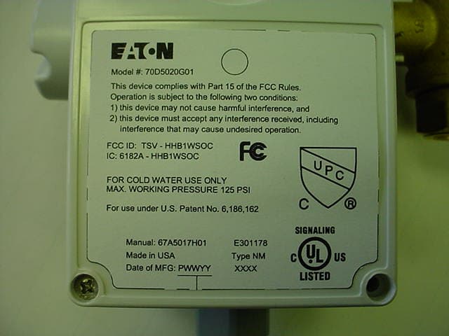
TSV-HHB1WSOC
Jul 11, 2006Monitoring Device
Equipment Class
DTS - Digital Transmission System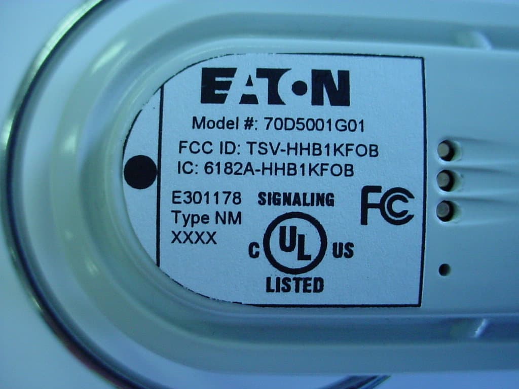
TSV-HHB1KFOB
Jun 01, 2006Controller/Monitor
Equipment Class
DTS - Digital Transmission System