TW4CT0022.4G Wireless camera
Shenzhen AEE Wireless Technology Co., Ltd.
Click to zoom
Application Details
- Equipment Class
- DXX - Part 15 Low Power Communication Device Transmitter
- Date of Grant
- Sep 04, 2007
- Application Purpose
- Original Equipment
- Date of Application
- Sep 04, 2007
- Equipment Note
- 2.4G Wireless camera
- Frequency Range
- 2414.00000000 - 2468.00000000
- Country
- China
Documents & Files
Document Text
Text extracted from the exhibit documents filed with the FCC. Open a document above to read the original.
Users Manual
English User's Manual Wireless Back-up Kit Weather-proof Model:002CF Please read this manual thoroughly before any attempt to install and operate this product and retain it for your future reference. TABLE OF CONTENTS INTRODUCTION 1~3 Notice 1 Approval Information (FCC/CE) 2~3 PRODUCT 4~5 Features 4 Package Contents 4 Feature Locations 5 INSTALLATION & USAGE 6~11 Camera Installation 6~7 Find Reversing Power 8 Find Anode +12V 10 SPECIFICATIONS 12 TROUBLESHOOTING 13 EU Environmental Protection Waste electrical products should not be disposed of with household waste. Please recycle where facilities exist. Check with your Local Authority or retailer for recycling advice. INTRODUCTION Thank you for purchasing our car back view monitor. This product works at ISM-2.4GHz frequency band, which could be legally used worldwide without permission. We f eel confident that you will be pleased with the quality and features of this product. The product is made of alloyed shell and special weather-proof enclosure that protect it against power and water sprays. It passed the IP65 testing. The product offers a new solution and experience for drivers. Drivers can check the back situations through the camera mounted on the rear car, and does not need to look back and forth. This product is only for accessorial reminding tool, thus we will not take any responsibility for resulting accident. Please read the manual thoroughly before using, and following the instruction accordingly. Notice Notice: This product may cause interferences with other wireless equipment that operates at 2.4GHz ISM band. Please turn off one of the equipments to eliminate the interference. Product Assurance: This camera will emit electromagnetic wave, just like other wireless products, however, its transmitting power is less than other wireless products such as mobile phones. The 2.4GHz wireless camera meets wireless frequency security standards and recommended indexes while working. These standards and indexes are certificated by academic organization and represent the cogitative research of the scientific workers who continuously explore and annotate the involved fields. So we believe that our products are safe for customers. Approval Information All our products meet the requirements of approval FCC or CE, and are granted the FCC or CE certification. They are authorized to bear FCC or CE mark. FCC This equipment has been tested and found to comply with the limits for a Class B digital device, pursuant to Part 15 of the FCC rules. These limits are designed to provide reasonable protection against harmful interference in a residential installation. This equipment generates, uses and can radiate radio frequency energy and, if not installed and used in accordance with the instructions, may cause harmful interference to radio communications. However, there is no guarantee that interference will not occur in a particular installation. If this equipment does cause harmful interference to radio or television reception, which can be determined by Features » 380TV lines clear picture display » 95° view angle for wide eyeshot» IP65 water resistance design for outdoor usage » Automatically start up the rear view images while reversing » 2.4”LCD screen display for vivid and bright images» Easy installation, suitable for cars and buses Package Contents This package comes with the following items. Please check whether they are all included in the packaging box, if one or some is missing, contact the retailer for replacement. ① Camera x1 ② LCD Monitor x1 ③ Detector x1 ④ Power Cable for Camera x1 ⑤ Power Cable for Receiver x1 ⑥ Mounting Hardware x1 ⑦ Double Face Tape x1 ⑧ User’s Manual x1 Note: The picture may vary from the actual object. Feature Locations INSTALLATION We strongly recommend you ask qualified technician or maintenance engineer to install this device. Improper installation of this monitor may cause battery leakage or short circuit. Please follow steps below to install the product. LCD Monitor Installation Camera Installation Camera Installation 1 Remove the screws from the license bracket, locate the camera on the license bracket and screw them tightly. 2 Put the power wires in order and put them through the hole of the license bracket then place them on the trunk for connection. 3 Connect the black pin of the camera to the black pin of the power cable. Note: Press the buckle on the black pin of the power cable to unplug the black pins. 4. Use the detector to detect the wire near reversing lights on the rear car body to find reversing power then connect the wire correctly. (Refer to Find Reversing Power section on Page8) Red wire connects to reversing power Black wire grounded Power Jack Find Reversing Power How to use the detector to find the power from the reverse power? 1 Step on the reverse gear. 2 Clip the pincers to the metal of the car body. 3 Use the red pen to find the power by thrusting into the tape. Make sure the penpoint touch the wire core. 4 If the LED light is on, find out the light wires. 5 Push the switch to the parking and use the red pen to detect it, if the light turns off, then the wire is the reverse power. 6 Connect the reverse power wire with the red wire of the camera and tie them together with the electronic tape. LCD Installation 1 Before permanently mounting the monitor, please clean the mounting place. And let it dry thoroughly. Stick the monitor bracket bottom with double tape face and press firmly to adhere tightly. 2 Press the monitor bracket firmly onto the area you just cleaned. Adhesive reaches maximum strength in 24 hours. Moving the fastener from its original position will weaken the adhesive and may damage the mounting surface. 3 Adjust the angle for perfect viewing effect. 4 Connect the power jack to the monitor and connect the black pin of the power jack with the black pin of the prolong cable. (Refer to Find Anode +12V section on Page10) Red wire connects to Anode +12V Black wire grounded Power …
Text truncated - open the document above for the full version.
External Photos
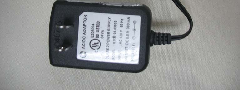
Project No.: 0707C144 Page 2 of 11 Neutron Engineering Inc. 0707C144 0707C144 Project No.: 0707C144 Page 2 of 11 Neutron Engineering Inc. 0707C144 0707C144 Project No.: 0707C144 Page 3 of 11 Neutron Engineering Inc. 0707C144 0707C144 Project No.: 0707C144 Page 3 of 11 Neutron Engineering Inc. 0707C144 0707C144 Project No.: 0707C144 Page 4 of 11 Neutron Engineering Inc. 0707C144 0707C144 Project No.: 0707C144 Page 4 of 11 Neutron Engineering Inc. 0707C144 0707C144 Project No.: 0707C144 Page 5 of 11 Neutron Engineering Inc. 0707C144
Internal Photos
Project No.: 0707C144 Page 6 of 11 Neutron Engineering Inc. 0707C144 0707C144 Project No.: 0707C144 Page 6 of 11 Neutron Engineering Inc. 0707C144 0707C144 Project No.: 0707C144 Page 7 of 11 Neutron Engineering Inc. 0707C144 0707C144 Project No.: 0707C144 Page 7 of 11 Neutron Engineering Inc. 0707C144 0707C144 Project No.: 0707C144 Page 8 of 11 Neutron Engineering Inc. 0707C144 0707C144 Project No.: 0707C144 Page 8 of 11 Neutron Engineering Inc. 0707C144 0707C144 Project No.: 0707C144 Page 9 of 11 Neutron Engineering Inc. 0707C144 0707C144 Project No.: 0707C144 Page 9 of 11 Neutron Engineering Inc. Ant 0707C144 0707C144 Project No.: 0707C144 Page 10 of 11 Neutron Engineering Inc. 0707C144 0707C144 Project No.: 0707C144 Page 10 of 11 Neutron Engineering Inc. 0707C144 0707C144 Project No.: 0707C144 Page 11 of 11 Neutron Engineering Inc. 0707C144 0707C144 Project No.: 0707C144 Page 11 of 11 Neutron Engineering Inc. 0707C144 0707C144
Test Report
Report No.: NEI-FCCP-1-0707C144 Page 2 of 46 Neutron Engineering Inc. Declaration Neutron represents to the client that testing is done in accordance with standard procedures as applicable and that test instruments used has been calibrated with the standards traceable to National Measurement Laboratory (NML) of R.O.C., or National Institute of Standards and Technology (NIST) of U.S.A. Neutron's reports apply only to the specific samples tested under conditions. It is manufacture’s responsibility to ensure that additional production units of this model are manufactured with the identical electrical and mechanical components. Neutronshall have no liability for any declarations, inferences o r generalizations drawn by the client or others from Neutron issued reports. Neutron’s reports must not be used by the client to claim product endorsement by the authorities or any agency of the Government. This report is the confidential property of the client. As a mutual protection to the clients, the public and Neutron-self, extracts from the test report shall not be reproduced except in full with Neutron’s authorized written approval. Neutron’s laboratory quality assurance procedures are in compliance with the ISO Guide 17025 requirements, and accredited by the conformity assessment authorities listed in this test report. Limitation For the use of the authority's logo is limited unless the Test Standard(s)/Scope(s)/Item(s) mentioned in this test report is (are) included in the conformity assessment authorities acceptance respective. Report No.: NEI-FCCP-1-0707C144 Page 3 of 46 Neutron Engineering Inc. Table of Contents Page 1 . SUMMARY OF TEST RESULTS 6 1.1 TEST FACILITY 7 1.2 MEASUREMENT UNCERTAINTY 7 2 . GENERAL INFORMATION 8 2.1 GENERAL DESCRIPTION OF EUT 8 2.2 DESCRIPTION OF TEST MODES 9 2.3 BLOCK DIGRAM SHOWING THE CONFIGURATION OF SYSTEM TESTED 10 2.4 DESCRIPTION OF SUPPORT UNITS 11 3 . EMC EMISSION TEST 12 3.1 CONDUCTED EMISSION MEASUREMENT 12 3.1.1 POWER LINE CONDUCTED EMISSION LIMITS 12 3.1.2 MEASUREMENT INSTRUMENTS LIST 12 3.1.3 TEST PROCEDURE 13 3.1.4 DEVIATION FROM TEST STANDARD 13 3.1.5 TEST SETUP 13 3.1.6 EUT OPERATING CONDITIONS 14 3.1.7 TEST RESULTS 15 3.2 RADIATED EMISSION MEASUREMENT 16 3.2.1 RADIATED EMISSION LIMITS 16 3.2.2 MEASUREMENT INSTRUMENTS LIST 17 3.2.3 TEST PROCEDURE 18 3.2.4 DEVIATION FROM TEST STANDARD 18 3.2.5 TEST SETUP 19 3.2.6 EUT OPERATING CONDITIONS 19 3.2.7 TEST RESULTS (Between 30 – 1000 MHz) 20 3.2.8 TEST RESULTS (Above 1000 MHz) 22 3.2.9 TEST RESULTS (2400 – 2483.5 MHz) 34 3.2.10 TEST RESULTS (Restricted Bands Requirements) 35 4 . BANDWIDTH TEST 39 4.1 MEASUREMENT INSTRUMENTS LIST 39 4.2 TEST PROCEDURE 39 4.3 DEVIATION FROM STANDARD 39 4.4 TEST SETUP 39 4.5 EUT OPERATION CONDITIONS 39 4.6 TEST RESULTS 40 Report No.: NEI-FCCP-1-0707C144 Page 4 of 46 Neutron Engineering Inc. Table of Contents Page 5 . ANTENNA CONDUCTED SPURIOUS EMISSION 42 5.1 APPLIED PROCEDURES / LIMIT 42 5.1.1 MEASUREMENT INSTRUMENTS LIST 42 5.1.2 TEST PROCEDURE 42 5.1.3 DEVIATION FROM STANDARD 42 5.1.4 TEST SETUP 42 5.1.5 EUT OPERATION CONDITIONS 43 5.1.6 TEST RESULTS 44 6 . EUT TEST PHOTO 46 Report No.: NEI-FCCP-1-0707C144 Page 5 of 46 Neutron Engineering Inc. 1. CERTIFICATION E q u i p m e n t : 2.4G WIRELESS CAMERA Trade Name : AEE Model Name. : CT002/CT002P A p p l i c a n t : SHENZHEN AEE TECHNOLOGY CO.,LTD Date of Test : Jul. 30, 2007 ~ Aug. 08, 2007 T e s t I t e m : ENGINEERING SAMPLE Standards : FCC Part15, Subpart C(15.249) / ANCI C63.4 : 2003 The above equipment has been tested and found compliance with the requirement of the relative standards by Neutron Engineering Inc. EMC Laboratory. The test data, data evaluation, and equipment configuration contained in our test report (Ref No. NEI-FCCP-1-0707C144) were obtained utilizing the test procedures, test instruments, test sites that has been accredited by the Authority of NVLAP and CNLA according to the ISO-17025 quality assessment standard and technical standard(s). Report No.: NEI-FCCP-1-0707C144 Page 6 of 46 Neutron Engineering Inc. 1. SUMMARY OF TEST RESULTS Test procedures according to the technical standards: FCC Part15, Subpart C Standard Section Test Item Judgment Remark 15.207 Conducted Emission - N/A 15.249 Radiated Spurious Emission PASS NOTE: (1)” N/A” denotes test is not applicable in this Test Report Report No.: NEI-FCCP-1-0707C144 Page 7 of 46 Neutron Engineering Inc. 1.1 TEST FACILITY The test facilities used to collect the test data in this report is C01/OS02 at the location of No.132-1, Lane 329, Sec. 2, Palain Road, Shijr City, Taipei, Taiwan. Neutron's test firm number is 95335 1.2 MEASUREMENT UNCERTAINTY The reported uncertainty of measurement y ± U,where expended uncertainty U is based on a standard uncertainty multiplied by a coverage factor of k=2,providing a level of confidence of approximately 95 %。 A. Conducted Measurement : Test Site Method Measurement Frequency Range U,(dB) NOTE C01 ANSI150 KHz ~ 30MHz 1.94 B. Radiated Measurement : Test Site Method Measurement Frequency Range Ant. H / V U,(dB) NOTE OS-01 ANSI30MHz ~ 200MHz V 3.82 30MHz ~ 200MHz H 3.60 200MHz ~ 1,000MHz V 3.86 200MHz ~ 1,000MHz H 3.94 OS-02 ANSI30MHz ~ 200MHz V 2.48 30MHz ~ 200MHz H 2.16 200MHz ~ 1,000MHz V 2.50 200MHz ~ 1,000MHz H 2.66 Report No.: NEI-FCCP-1-0707C144 Page 8 of 46 Neutron Engineering Inc. 2. GENERAL INFORMATION 2.1 GENERAL DESCRIPTION OF EUT Equipment 2.4G WIRELESS CAMERA Trade Name AEE Model Name. CT002/CT002P OEM Brand/Model No. N/A Model Difference CT002P has one more lens IC than CT002(PCB layout are the same) IC controlled by software Product Description The EUT is a 2.4G WIRELESS CAMERA. Product Type Low Power Communication Device Operation Frequency: 2414~2468 MHz Modulation Type: GFSK Number Of Channel 4 CH Output Power: 75.16 dBuV/m (AV Max.) Based on the application, features, or specification exhibited in User's Manual, the EUT is considered as an ITE/Computing Device. More details of EUT technical specifica…
Text truncated - open the document above for the full version.
Test Setup Photos
Report No.: NEI-FCCP-1-0707C144 Page 45 of 45 Neutron Engineering Inc. Radiated Measurement Photos TX Mode Report No.: NEI-FCCP-1-0707C144 Page 45 of 45 Neutron Engineering Inc. Radiated Measurement Photos TX Mode
Contact Information
Applicant
James Xiao
Test Firm
BTL Inc.Andy Yeh
Technical Specifications
| # | Rule Parts | Frequency Range | Power Output |
|---|---|---|---|
| 1 | 15C | 2.41 GHz - 2.47 GHz | - |
Other Applications from Shenzhen AEE Wireless Technology Co., Ltd.
TW4870VL
Apr 06, 20082.4G Wireless Transceiver
Equipment Class
DXX - Part 15 Low Power Communication Device Transmitter
TW4-AT202-900M
Apr 06, 2008Wireless IP Camera
Equipment Class
DXX - Part 15 Low Power Communication Device Transmitter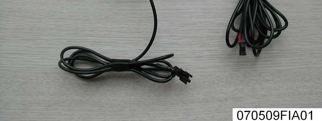
TW4CT011
Jun 18, 20072.4 GHz Wireless Camera
Equipment Class
DXX - Part 15 Low Power Communication Device Transmitter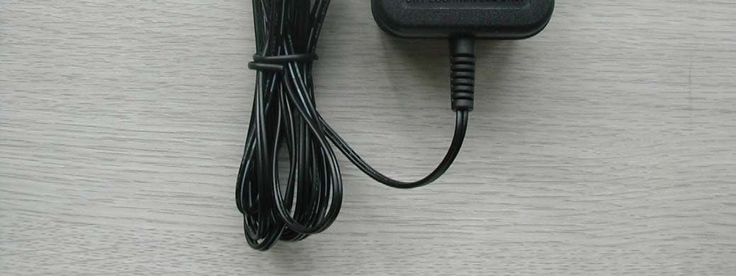
TW4BT501
Dec 20, 20062.4 Ghz Wireless Camera
Equipment Class
DXX - Part 15 Low Power Communication Device Transmitter
TW4AT133
Nov 14, 20062.4GHz Wireless Camera
Equipment Class
DXX - Part 15 Low Power Communication Device Transmitter